Note: Descriptions are shown in the official language in which they were submitted.
CA 02803425 2013-01-24
256087-4
HOLLOW ROTOR MOTOR AND SYSTEMS COMPRISING THE SAME
[1] This application claims priority from United States Provisional
Application
having serial number 61/592,191 filed January 30, 2012 and which is
incorporated herein
by reference in its entirety.
BACKGROUND
[2] In one aspect, the present invention provides advanced motor technology
which is particularly useful for well fluids lifting systems. A major
challenge is to
provide well fluids lifting systems which can withstand the extreme pressure
and
temperature of thermal energy recovery wells while providing sufficient
longevity to
meet the needs of the Enhanced Geothermal Systems (EGS) industry for the
coming
years. At present, there are few, if any, viable well fluids lifting systems
capable of
prolonged operation within the types of geothermal wells needed to provide
significant
amounts of geothermal energy for human use.
BRIEF DESCRIPTION
[3] In one embodiment, the present invention provides an electric motor
comprising a motor housing; and a hollow rotor configured to rotate within and
be driven
by a stator contained within the motor housing; wherein the motor housing is
characterized by a largest cross-sectional area of the motor housing, and
wherein the
hollow rotor defines a flow channel characterized by a smallest cross-
sectional area of the
flow channel, wherein the smallest cross-sectional area of the flow channel is
at least
25% of the largest cross-sectional area of the motor housing, and wherein the
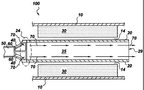
hollow
rotor has a first end portion defining a fluid inlet, and a second end portion
defining a
fluid outlet; the fluid inlet, the flow channel and the fluid outlet being
configured to allow
passage of a fluid from the fluid inlet to the fluid outlet via the flow
channel.
1
CA 02803425 2013-01-24
256087-4
[4] In another embodiment, the present invention provides an electric fluid
pump
comprising: (a) an electric motor comprising: (i) a motor housing; and (ii) a
hollow rotor
configured to rotate within and be driven by a stator contained within the
motor housing;
wherein the motor housing is characterized by a largest cross-sectional area
of the motor
housing, and wherein the hollow rotor defines a flow channel characterized by
a smallest
cross-sectional area of the flow channel, wherein the smallest cross-sectional
area of the
flow channel is at least 25% of the largest cross-sectional area of the motor
housing, and
wherein the hollow rotor has a first end portion defining a fluid inlet, and a
second end
portion defining a fluid outlet; the fluid inlet, the flow channel and the
fluid outlet being
configured to allow passage of a fluid from the fluid inlet to the fluid
outlet via the flow
channel; (b) a transition section configured to join the hollow rotor to a
drive shaft of a
pumping device to be powered by the motor; (c) one or more intake ports
defined by the
transition coupling, the first end portion, or both the transition coupling
and the first end
portion; said intake ports being in fluid communication with the flow channel
of the
hollow rotor; and (d) a pumping device comprising a fluid inlet and one or
more
impellers fixed to a drive shaft powered by the electric motor.
[5] In yet another embodiment, the present invention provides a machine for
electric power generation comprising: (a) a generator comprising: (i) a
generator housing;
and (ii) a hollow magnetic rotor configured to rotate within a stator
contained within the
generator housing; wherein the generator housing is characterized by a largest
cross-
sectional area of the generator housing, and wherein the hollow magnetic rotor
defines a
flow channel characterized by a smallest cross-sectional area of the flow
channel,
wherein the smallest cross-sectional area of the flow channel is at least 25%
of the largest
cross-sectional area of the generator housing, and wherein the hollow magnetic
rotor has
a first end portion defining a fluid inlet, and a second end portion defining
a fluid outlet;
the fluid inlet, the flow channel and the fluid outlet being configured to
allow passage of
a fluid from the fluid inlet to the fluid outlet via the flow channel; (b) a
transition section
configured to join the hollow magnetic rotor to a drive shaft of a turbine
device
configured to drive the hollow magnetic rotor; and (c) one or more intake
ports defined
2
CA 02803425 2013-01-24
256087-4
by the transition coupling, the first end portion, or both the transition
coupling and the
first end portion; said intake ports being in fluid communication with the
flow channel of
the hollow magnetic rotor; wherein the turbine device comprises one or more
impellers
fixed to the drive shaft.
[6] In yet another embodiment, the present invention provides an electric
fluid
pump which is an Electric Submersible Pump (ESP) optimized for operation
within a
well bore.
BRIEF DESCRIPTION OF DRAWING FIGURES
[7] These and other features, aspects, and advantages of the present
invention will
become better understood when the following detailed description is read with
reference
to the accompanying drawings in which like characters represent like parts
throughout the
drawings, wherein:
[8] FIG. 1 illustrates one or more embodiments of the present invention;
[9] FIG. 2 illustrates one or more embodiments of the present invention;
[10] FIG. 3 illustrates one or more embodiments of the present invention;
[11] FIG. 4 illustrates one or more embodiments of the present invention;
[12] FIG. 5 illustrates one or more embodiments of the present invention;
[13] FIG. 6 illustrates one or more embodiments of the present invention
and FIG.
6A is an end view of FIG. 6;
[14] FIG. 7 illustrates one or more embodiments of the present invention;
[15] FIG. 8 illustrates one or more embodiments of the present invention;
[16] FIG. 9 illustrates one or more embodiments of the present invention;
[17] FIG. 10 illustrates one or more embodiments of the present invention;
3
CA 02803425 2013-01-24
256087-4
[18] FIG. 11 illustrates one or more embodiments of the present invention;
and
[19] FIG. 12 illustrates one or more embodiments of the present invention.
DETAILED DESCRIPTION
[20] As noted, in one embodiment, the present invention provides an
electric motor
comprising a motor housing; and a hollow rotor configured to rotate within and
be driven
by a stator contained within the motor housing; wherein the motor housing is
characterized by a largest cross-sectional area of the motor housing, and
wherein the
hollow rotor defines a flow channel characterized by a smallest cross-
sectional area of the
flow channel, wherein the smallest cross-sectional area of the flow channel is
at least
25% of the largest cross-sectional area of the motor housing, and wherein the
hollow
rotor has a first end portion defining a fluid inlet, and a second end portion
defining a
fluid outlet; the fluid inlet, the flow channel and the fluid outlet being
configured to allow
passage of a fluid from the fluid inlet to the fluid outlet via the flow
channel.
[21] A variety of motor topologies may be used, including Surface Mounted
Permanent Magnet, Internal Permanent Magnet, Induction, Wound Field,
Synchronous
Reluctance, and Switched Reluctance topologies. In one or more embodiments the
motor
is of the Surface Mounted Permanent Magnet type.
[22] In one or more embodiments the electric motor provided by the present
invention, is characterized by a smallest cross-sectional area of the flow
channel of from
25% to about 75% of the largest cross-sectional area of the motor housing.
[23] In one or more embodiments the electric motor provided by the present
invention, is characterized by a smallest cross-sectional area of the flow
channel of from
30% to about 55% of the largest cross-sectional area of the motor housing.
[24] In one or more embodiments the electric motor provided by the present
invention further comprises a transition section (at times herein referred to
as a transition
coupling) configured to join the hollow rotor to a drive shaft of a device to
be powered by
4
CA 02803425 2013-01-24
256087-4
the motor; and one or more intake ports defined by the transition coupling,
the first end
portion, or both the transition coupling and the first end portion; said
intake ports being in
fluid communication with the flow channel of the hollow rotor. In one or more
embodiments the transition section is a coupling which may be integral to or
separate
from either the hollow rotor or the drive shaft of the device.
[25] In one or more embodiments the transition coupling defines one or more
intake
ports. In another embodiment, the first end portion defines one or more intake
ports. In
yet another embodiment, both the transition coupling and the first end portion
each define
at least one intake port. In yet another embodiment, only the transition
coupling defines
one or more intake ports.
[26] In one or more embodiments, the electric motor further comprises a
dielectric
fluid, at times herein referred to as a dielectric coolant fluid. In one or
more
embodiments, a dielectric fluid filled gap separates an outer surface of the
hollow rotor
from the stator. Suitable dielectric coolant fluids include silicone oils,
aromatic
hydrocarbons such as biphenyl, diphenylether, fluorinated polyethers, silicate
ester fluids,
perfluorocarbons, alkanes, and polyalphaolefins.
[27] In another embodiment, a gas fluid filled gap separates an outer
surface of the
hollow rotor from the stator. In one embodiment, the gas within the gap may be
air. In
another embodiment, the gas within the gap may be a relatively inert gas such
as helium
or argon. In one embodiment, the gas within the gap is nitrogen.
[28] In one or more embodiments, the motor provided by the present
invention
comprises an encapsulated stator such as those described in United States
Patent
7847454, United States Divisional Application 12/904523, and United States
Patent
Applications 12/915604 and 12/940524 which are incorporated by reference in
their
entirety.
[29] As noted, in one or more embodiments the present invention provides an
electric fluid pump comprising: (a) an electric motor comprising: (i) a motor
housing; and
CA 02803425 2013-01-24
256087-4
(ii) a hollow rotor configured to rotate within and be driven by a stator
contained within
the motor housing; wherein the motor housing is characterized by a largest
cross-
sectional area of the motor housing, and wherein the hollow rotor defines a
flow channel
characterized by a smallest cross-sectional area of the flow channel, wherein
the smallest
cross-sectional area of the flow channel is at least 25% of the largest cross-
sectional area
of the motor housing, and wherein the hollow rotor has a first end portion
defining a fluid
inlet, and a second end portion defining a fluid outlet; the fluid inlet, the
flow channel and
the fluid outlet being configured to allow passage of a fluid from the fluid
inlet to the
fluid outlet via the flow channel; (b) a transition section configured to join
the hollow
rotor to a drive shaft of a pumping device to be powered by the motor; (c) one
or more
intake ports defined by the transition coupling, the first end portion, or
both the transition
coupling and the first end portion; said intake ports being in fluid
communication with
the flow channel of the hollow rotor; and (d) a pumping device comprising a
fluid inlet
and one or more impellers fixed to a drive shaft powered by the electric
motor.
[30] In one or more embodiments, the electric fluid pump provided by the
present
invention comprises a first set of impellers mounted on a first drive shaft,
and a second
set of impellers mounted on a second driveshaft, said first and second drive
shafts being
configured to be driven by the hollow rotor, said first and second drive
shafts being
configured to rotate in opposite directions.
[31] In one or more embodiments, the electric fluid pump provided by the
present
invention comprises a pumping device housing (also referred to as a pump
housing)
defining a fluid inlet and containing a pump section comprising one or more
impellers
fixed to a drive shaft powered by the electric motor. In one or more
embodiments, the
electric fluid pump comprises stationary diffusers mounted to an inner surface
of the
pumping device housing.
[32] In yet another embodiment, the present invention provides a machine
for
electric power generation comprising: (a) a generator comprising: (i) a
generator housing;
and (ii) a hollow magnetic rotor configured to rotate within a stator
contained within the
6
CA 02803425 2013-01-24
256087-4
generator housing; wherein the generator housing is characterized by a largest
cross-
sectional area of the generator housing, and wherein the hollow magnetic rotor
defines a
flow channel characterized by a smallest cross-sectional area of the flow
channel,
wherein the smallest cross-sectional area of the flow channel is at least 25%
of the largest
cross-sectional area of the generator housing, and wherein the hollow magnetic
rotor has
a first end portion defining a fluid inlet, and a second end portion defining
a fluid outlet;
the fluid inlet, the flow channel and the fluid outlet being configured to
allow passage of
a fluid from the fluid inlet to the fluid outlet via the flow channel; (b) a
transition section
configured to join the hollow magnetic rotor to a drive shaft of a turbine
device
configured to drive the hollow magnetic rotor; and (c) one or more outlet
ports defined by
the transition coupling, the first end portion, or both the transition
coupling and the first
end portion; said intake ports being in fluid communication with the flow
channel of the
hollow magnetic rotor; wherein the turbine device comprises one or more
impellers fixed
to the drive shaft.
[33] In one or more embodiments, the machine for electric power generation
provided by the present invention further comprises a turbine device housing
defining
one or more fluid outlets. In one or more embodiments, the machine for
electric power
generation provided by the present invention further comprises a turbine
device housing
defining one or more fluid inlets.
[34] In one or more embodiments, the machine for electric power generation
provided by the present invention further comprises a pressurized dielectric
fluid in a gap
separating the outer surface of the hollow rotor from the stator.
[35] In one or more embodiments, the machine for electric power generation
provided by the present invention comprises an encapsulated stator.
[36] Referring now to the figures, FIG. 1 illustrates a large diameter
electric motor
100 provided by the present invention, the motor comprising a motor housing 10
and a
hollow rotor 20 disposed within the motor. Hollow rotor 20 is configured to
rotate within
7
CA 02803425 2013-01-24
256087-4
and be driven by stator 30 which is contained within the motor housing. A gap
14
separates the outer surface of the hollow rotor from the stator. Gap 14 is at
times herein
referred to as an air gap, but may in one or more embodiments be filled with a
dielectric
coolant fluid, air or another fluid. Hollow rotor 20 defines a flow channel 25
characterized by a smallest cross-sectional area 22. Similarly, motor housing
10 is
characterized by a largest cross-sectional area 12. In one or more embodiments
both the
flow channel 25 and motor housing 10 are cylindrical in shape, and are
characterized by a
single flow channel cross-sectional area and a single motor housing cross-
sectional area.
Under such circumstances, the cross-sectional area of flow channel 25 is at
least 25% of
the cross-sectional area of motor housing 10. In the embodiment shown, hollow
rotor 20
has a first end portion 24 defining a fluid inlet 27. Hollow rotor 20 further
defines a
second end portion 26 defining fluid outlet 29. The fluid inlet 27, the flow
channel 25
and the fluid outlet 29 are in fluid communication such that a fluid, for
example a liquid,
entering the hollow rotor via the fluid inlet may pass through the flow
channel and exit
the fluid outlet.
[37]
Referring now to FIG. 2, the figure illustrates a large diameter electric
motor
100 provided by the present invention, the motor comprising a transition
coupling 40 (at
times herein referred to as a transition section) configured to join the
hollow rotor 20 to a
drive shaft 50 of a device (not shown) to be powered by the motor. In the
embodiment
shown, intake ports 60 allow a fluid to pass into flow channel 25 as suggested
by flow
direction arrows 70. In one or more embodiments the transition coupling 40 is
separate
from the hollow rotor and the drive shaft 50 and couples to each, for example
by friction
joints, shrink fittings, threading, or a combination thereof. In one or more
embodiments,
the transition coupling is integral to the hollow rotor and couples to drive
shaft 50. In one
or more embodiments, the transition coupling is integral to the drive shaft of
the device to
be powered by the motor and couples to the hollow rotor. In one or more
embodiments
the intake ports 60 are characterized by one or more cross sectional areas,
and a sum of
these cross sectional areas of the intake ports is substantially equal to, or
larger than, the
smallest cross-sectional area of the flow channel 25.
8
CA 02803425 2013-01-24
256087-4
[38] Referring now to FIG. 3, the figure illustrates a large diameter
electric motor
100 provided by the present invention. In the embodiment shown, the motor is
coupled
to drive shaft 50 of a pump configured to pump a fluid into and through flow
channel 25.
In one or more embodiments, a fluid may be impelled by a series of impellers
(not
shown) axially along drive shaft 50 toward and though intake ports 60. Seals
80 prevent
this working fluid from entering the motor and coming into contact with
internal motor
components such as the stator. In one or more embodiments, the motor is filled
with a
pressurized dielectric fluid which is at a higher pressure than the
environment outside of
the motor. In one or more embodiments the pressurized dielectric fluid leaks
outwardly
from the motor interior as a means of preventing ingress of the working fluid
into the
interior of the motor. Seals 80 are typically of the face seal type. In one or
more
embodiments, seal 80 comprises a stationary seal component fixed within the
motor
housing and a moving seal component attached to the hollow rotor, the
stationary seal
component and moving seal component defining a leakage pathway through which a
pressurized dielectric fluid may flow. In the embodiment shown, transition
coupling 40
is shown as integral to drive shaft 50 and as defining intake ports 60. In the
embodiment
shown, transition coupling 40 defines intake ports 60, and the first end
portion (FIG. 1) of
the hollow rotor lacks intake ports.
[39] Referring now to FIG. 4, the figure illustrates a large diameter
electric motor
100 provided by the present invention. In the embodiment shown, transition
coupling 40
is shown as integral to hollow rotor 20. It should be noted that transition
coupling 40, in
this or any other embodiment, is not considered when determining the smallest
cross-
sectional area of the flow channel. In the embodiment shown, the motor is
configured to
power drive shaft 50 of a pump section (not shown) which acts upon and moves a
working fluid (not shown) axially along drive shaft 50 as indicated by
direction arrows
70. The working fluid enters flow channel 25 via intake ports 60. In the
embodiment
shown, the first end portion (FIG. 1) of the hollow rotor 20 defines intake
ports 60 and
transition coupling 40 lacks intake ports.
9
CA 02803425 2013-01-24
256087-4
[40] Referring now to FIG. 5, the figure illustrates an electric fluid pump
according
to one or more embodiments of the present invention. The electric fluid pump
comprises
a large diameter electric motor 100 configured to power a pump 200. In the
embodiment
shown, only a portion of pump 200 is visible. Pump 200 comprises a pump
housing 210
and impellers 257 attached to drive shaft 50 which is coupled to hollow rotor
20 of large
diameter electric motor 100 via transition coupling 40. In the embodiment
shown,
transition coupling 40 is an independent component (i.e. not integral to
either of drive
shaft 50 or hollow rotor 20) joining to both drive shaft 50 and hollow rotor
20.
Transition coupling 40 defines intake ports 60, and no intake ports are
defined by hollow
rotor 20. Electric motor 100 comprises motor housing 10 which, in the
embodiment
shown, is joined to pump housing 210 on the fluid inlet end of the hollow
rotor and is
joined to conduit 90 on the outlet end of the hollow rotor. In one or more
embodiments,
conduit 90 is configured to receive fluid impelled by pump 200 through flow
channel 25
of hollow rotor 20 as indicated by fluid direction arrows 70.
[41] Referring now to FIG. 6, the figure illustrates an electric fluid pump
according
to one or more embodiments of the present invention. The electric fluid pump
comprises
a large diameter electric motor 100 configured to power a pump 200. In the
embodiment
shown, only a portion of motor 100 is visible. Pump 200 comprises a pump
housing 210
and impellers 257 attached to drive shaft 50 which is coupled to hollow rotor
20 of large
diameter electric motor 100 via transition coupling 40. In the embodiment
shown,
transition coupling 40 is an independent component (i.e. not integral to
either of drive
shaft 50 or hollow rotor 20) joining to both drive shaft 50 and hollow rotor
20. Pump
200 also comprises stationary diffusers 253 and thrust bearings 252. Thrust
bearings 252,
at times herein referred to as thrust washers, are positioned between the
stationary
diffusers and the rotatory impellers. In the embodiment shown, drive shaft 50
is shown
as supported by radial bearing 251 which is shown in an enlarged end-on view
in FIG. 6a
in which radial bearing 251 is supported by support struts 215. Although only
a single
radial support bearing is featured in FIG. 6, a plurality of radial bearings
is typically
CA 02803425 2013-01-24
256087-4
included in the large diameter electric motors, electric fluid pumps, and
machines for
electric power generation provided by the present invention.
[42] Referring now to FIG. 7, the figure illustrates a transition coupling
40
according to one or more embodiments of the present invention. In the
embodiment
shown, the transition coupling is a single independent component configured to
be joined
via first coupling 41 to a drive shaft (50) and configured to be joined via a
second
coupling 42 to a hollow rotor (20). The transition coupling defines a
plurality of intake
ports 60. In the embodiment shown, transition coupling 40 may join to each of
drive
shaft 50 and hollow rotor 20 via, for example, friction joints, shrink fit
joints, or a
combination thereof.
[43] Referring now to FIG. 8, the figure illustrates a transition section
40 which is
integral to and forms part of a hollow rotor 20 according to one or more
embodiments of
the present invention. Transition section 40 includes a first coupling
configured to join to
drive shaft of a device configured to be driven by hollow rotor 20. While both
first
coupling 41 and intake ports 60 are integral to and form a part of hollow
rotor 20, the
transition section 40 is not considered in calculation of the smallest cross-
sectional area
22 of flow channel 25.
[44] Referring now to FIG. 9, the figure illustrates a machine for electric
power
generation according to one or more embodiments of the present invention. In
the
embodiment shown, the machine comprises a generator 900 comprising a generator
housing 910 and a hollow magnetic rotor 920 configured to rotate within a
stator 30
contained within the generator housing. The generator housing 910 is
characterized by a
largest cross-sectional area. The hollow magnetic rotor defines a flow channel
25 running
the length of the hollow magnetic rotor and being characterized by a smallest
cross-
sectional area, the smallest cross-sectional area of the flow channel being at
least 25% of
the largest cross-sectional area of the generator housing. The hollow magnetic
rotor has a
first end portion 24 defining a fluid outlet 29, and a second end portion 26
defining a
fluid inlet 27. The fluid inlet, the flow channel and the fluid outlet are in
fluid
11
CA 02803425 2013-01-24
256087-4
communication such that a fluid entering the flow channel 25 via the fluid
inlet 27 may
pass through flow channel 25 and exit the hollow magnetic rotor via fluid
outlet 29. The
fluid inlet, the flow channel and the fluid outlet may be said to be
configured to allow
passage of a fluid from the fluid inlet to the fluid outlet via the flow
channel. The
machine for electric power generation comprises a transition section 40
configured to join
the hollow magnetic rotor to a drive shaft of a turbine device configured to
drive the
hollow magnetic rotor. In the embodiment shown, transition section 40 is shown
as
defining outlet ports 960 configured to allow passage of fluid from the flow
channel and
fluid outlet of the hollow magnetic rotor. Transition section 40 is coupled to
drive shaft
50 of turbine 1000 (at times herein referred to as a turbine device). In the
embodiment
shown, turbine 1000 comprises turbine blades 957 and turbine housing 1010.
[45] In one or more embodiments, during operation, the machine for electric
power
generation illustrated in FIG. 9 generates electricity as follows. A fluid
flowing under
pressure enters hollow magnetic rotor hollow via fluid inlet 27 and flows
through flow
channel 25 as indicated by direction arrows 70. Fluid passes into the
transition section
and exits into the cavity defined by generator housing 910 and turbine housing
1010. The
fluid flowing under pressure encounters and turbine blades 957 during its
passage
through the turbine. Energy from the fluid is transferred to the turbine
blades causing the
blades and drive shaft 50 to rotate. The rotation of drive shaft 50, in turn,
causes the
hollow magnetic rotor 920 to rotate in close proximity to stator 30 and
generating electric
power thereby. The fluid, having transferred a portion of its contained energy
to the
turbine then passes out of turbine 1000 via turbine fluid outlet 1027.
[46] In one or more embodiments, the turbine housing defines one or more
fluid
inlets 1028. These may be useful when the machine for electric power
generation is
operated in a confined space such as a pipe or a well bore or other conduit
wherein a
portion of the fluid flowing under pressure is allowed to flow along the outer
surface of
generator housing 910. For example a fluid flowing under pressure may
encounter the
fluid inlet 27 end of the machine for electric power generation disposed
within a conduit
12
CA 02803425 2013-01-24
256087-4
such that a gap exists between the outer surface of the generator housing and
the inner
wall of the conduit. A first portion of the fluid flowing under pressure
passes into flow
channel 25 while a second portion of the fluid passes along the outer surface
of the
generator housing. The second portion then encounters the outer surface of the
turbine
housing which defines fluid inlets 1028. Some or all of the second portion of
the fluid
enters the turbine and contacts the turbine blades and a portion of the energy
contained in
the second portion of the fluid is transferred to the turbine. In one or more
embodiments,
the turbine housing is configured to partially or completely occlude fluid
passage
between the outer surface of the turbine housing and the inner wall of the
conduit.
[47] Those of ordinary skill in the art will appreciate the close
relationship between
one or more embodiments of the machine for electric power generation provided
by the
present invention and one or more embodiments of the electric fluid pump
provided by
the present invention. Thus, simply reversing the direction of fluid flow and
electric
current flow may convert a power consuming electric fluid pump into an
electric power
generating machine. In the context of a geothermal production well, for
example, an
electric fluid pump provided by the present invention and disposed within a
geothermal
production well may pump hot water from a geothermal field to a thermal energy
extraction facility at the surface.
[48] Referring now to FIG. 10, the figure illustrates an electric fluid
pump 300
according to one or more embodiments of the present invention. The pump
comprises a
hollow rotor electric motor (not shown) provided by the present invention and
pumping
section 200 comprising a first set of impellers 257 mounted on a first drive
shaft 50
configured to rotate in direction 51, and a second set of impellers 258
mounted on a
second driveshaft 52 configured to rotate in direction 53, said first and
second drive
shafts being configured to be driven by the hollow rotor, said first and
second drive shafts
being configured to rotate in opposite directions via planetary gear box 54.
[49] Referring now to FIG. 11, the figure illustrates a seal 80 within a
hollow rotor
electric motor according to one or more embodiments of the present invention.
The figure
13
CA 02803425 2013-01-24
256087-4
shows a portion of a hollow magnetic rotor 1120 having a rotor shaft 1105
defining a
flow channel 25. Permanent magnets 1110 are attached to the outer surface of
the rotor
shaft 1105 by magnet retaining ring 1115. In the embodiment shown, the motor
contains
a pressurized dielectric fluid 21 in contact with stator 30 and filling the
gap 14 between
the outer surface of the hollow rotor magnetic rotor 1120 and stator 30. Seal
80 prevents
ingress of working fluid (not shown) into the internal parts of the motor 100.
Seal 80
comprises a rotating portion 16 fixed to the outer surface of and rotates with
hollow rotor
magnetic rotor 1120. Seal 80 also comprises a stationary portion comprised of
fixed seal
portion 17, seal bellows 18 and seal mount 19 attached to a non-moving surface
of the
motor, in the embodiment shown to the motor housing. Seal 80 defines a seal
leakage
path 15 through which a small amount of the pressurized dielectric fluid 21
may flow
thereby preventing ingress of the working fluid into the internal parts of the
motor.
[50]
Referring now to FIG. 12, the figure illustrates a geothermal well and thermal
energy extraction system 1200 according to one or more embodiments of the
present
invention. In the embodiment shown, an electric fluid pump 300 provided by the
present
invention and comprising hollow rotor electric motor 100 and pump section 200
is
disposed within a geothermal production well 1220. Production well 1220 is
supplied
with hot water 1230 from geothermal field 1205. In one embodiment, hot water
1230 is
at a temperature of 300 C and a pressure of 300 bar. Hot water from geothermal
field
1205 enters geothermal production well 1220 and is impelled to the surface by
electric
fluid pump 300 powered by electric cable 1225. At the surface, energy 1240 is
extracted
from the hot water in an energy recovery unit 1210 coupled to production well
1220 at
wellhead 1215. As will be appreciated by those of ordinary skill in the art,
various
methods may be employed including producing steam and driving an electric
turbine. In
one embodiment, the energy recovery unit comprises an organic Rankine cycle.
Cooled
water 1235 produced by removing energy from hot water 1230 is returned to
geothermal
field 1205 via injection well 1250 where it absorbs heat from the field to
produce hot
water 1230.
14
CA 02803425 2013-01-24
256087-4
[51] As noted, in one embodiment, the present invention provides an
electric motor
comprising a motor housing; and a hollow rotor configured to rotate within and
be driven
by a stator contained within the motor housing; wherein the motor housing is
characterized by a largest cross-sectional area of the motor housing, and
wherein the
hollow rotor defines a flow channel characterized by a smallest cross-
sectional area of the
flow channel, wherein the smallest cross-sectional area of the flow channel is
at least
25% of the largest cross-sectional area of the motor housing, and wherein the
hollow
rotor has a first end portion defining a fluid inlet, and a second end portion
defining a
fluid outlet; the fluid inlet, the flow channel and the fluid outlet being
configured to allow
passage of a fluid from the fluid inlet to the fluid outlet via the flow
channel.
[52] Such motors are useful for a wide variety of applications. For
example, the
motors provided by the present invention may be used in situations in which,
during
operation, the motor is disposed within a confined space such as a pipe, a
shipboard
compartment or a well bore. In one embodiment, the present invention provides
a motor
useful in an in-line pump capable of moving a fluid at relatively high rates
as compared
to conventional in-line pumps. It is believed that the motors provided by the
present
invention and the pumping systems comprising them will be useful in a wide
variety of
applications, such as in-line pumps in high flow rate on-board fire-fighting
systems,
compact high flow rate shipboard emergency water removal systems, in-line high
flow
fluid transfer pumps in chemical manufacture and distribution, in-line high
flow fluid
transfer pumps in petroleum refining and distribution, and in line high flow
fluid transfer
pumps which can maintained in an aseptic environment needed in medical and
food
applications.
[53] As noted, in one embodiment the present invention provides an electric
fluid
pump which is an Electric Submersible Pump (ESP) optimized for operation
within a
well bore and comprising at least one hollow rotor motor provided by the
present
invention. In one or more embodiments of the present invention, the ESP
comprises one
or more electric motors configured to one or more pumping sections. In one
CA 02803425 2013-01-24
256087-4
embodiment, the Electric Submersible Pump (ESP) is optimized for operation
within a
geothermal well bore having a bore diameter of about 10.625 inches. In one
such
embodiment, the ESP is configured to utilize approximately 5.0 MW of power,
the
amount needed to boost 80 kg/second (kg/s) of a 300 C working fluid (water,
with a gas
fraction of 2% or less) at a pressure of 300 bar. In such an embodiment, the
ESP can be
operated to advantage at a pump/motor speed of about 3150 RPM in order to
balance
system efficiency and pump stage pressure rise with motor thermal concerns. In
one or
more embodiments, the ESP provided by the present invention comprises
approximately
126 impeller/diffuser stages having a total length of about 19 meters and a
hollow rotor
electric motor sections having a length of about 16 meters, making the
combined total
length of the ESP motor and pumping sections approximately 35 meters. The
total length
of an ESP provided by the present invention is typically somewhat longer than
the sum of
the lengths of the motor and pumping sections due to the presence of
additional structural
features arrayed along the ESP pump-motor axis, for example a protector
section
(discussed herein). The total length of an ESP provided by the present
invention may
vary widely, but in geothermal production well applications, the length of
such an ESP
will typically fall in a range between 30 and 50 meters. A design-of-
experiments analysis
using Computational Fluid Dynamics (CFD) carried out by the inventors revealed
that
pump efficiency as high as 78% could be achieved at a flow rate of 80
kg/second through
an ESP according to one or more embodiments of the present invention. In one
aspect,
the present invention provides an ESP comprising an induction motor. In an
alternate
embodiment, the present invention provides an ESP comprising a permanent
magnet
motor. During operation, water impelled by the ESP impeller/diffuser stages
passes
primarily into and through the bore (also referred to herein at times as the
flow channel)
of the hollow rotor. In one or more embodiments, the ESP provided by the
present
invention comprises a modular motor that has been optimized for power density
and is
divided into 8-10 sections, with a total motor length of approximately 16
meters. High
temperature testing of various motor insulation materials, and high-
temperature high-
pressure evaluations of candidate dielectric coolant fluids have been carried
out and
suitable candidate motor insulation materials and dielectric coolant fluids
have been
16
CA 02803425 2013-01-24
256087-4
identified. These include for example, motor insulation materials disclosed in
United
States Patent Applications No.s 12/968437 and 13/093306 which are incorporated
by
reference herein in its entirety, and dielectric fluids known in the art, for
example
perfluorinated polyethers. With a combination of thermal management using
circulating
dielectric oil, as well as the use of inorganic solid motor insulation
materials, a peak
motor temperature of <330 C is attainable and acceptable. In one or more
embodiments
the ESP provided by the present invention comprises a high pressure, high
temperature
dielectric fluid flow loop. As will be appreciated by those of ordinary skill
in the art the
use of a pressurized dielectric fluid within the motor portion of an ESP
requires the use of
one or more seals to isolate the dielectric fluid from the process fluid.
[54] This
written description uses examples to disclose the invention, including the
best mode, and also to enable any person skilled in the art to practice the
invention,
including making and using any devices or systems and performing any
incorporated
methods. The patentable scope of the invention is defined by the claims, and
may include
other examples that occur to those skilled in the art. Such other examples are
intended to
be within the scope of the claims if they have structural elements that do not
differ from
the literal language of the claims, or if they include equivalent structural
elements with
insubstantial differences from the literal language of the claims.
17