Note: Descriptions are shown in the official language in which they were submitted.
CA 02803530 2013-01-30
1
METHOD AND APPARATUS FOR CONTROLLING THE OPERATION OF
CLUSTER DRILL OF DTH HAMMERS
Field of the Invention:
[0001] The present invention relates generally to civil building
construction.
More specifically, the present invention relates to techniques and equipments
used in
building structural foundation piling. Still more specifically, the present
invention
relates to methodology and equipment for controlling the operation of cluster
drill of
down-the-hole (DTH) percussion hammers for drilling in ground.
Background:
[0002] Conventional ground drilling equipments or techniques normally
drill
holes with a single or outer diameter (OD) target. Depending on the ground
condition,
a casing sometimes is inserted in the ground to prevent collapse of soil when
the
ground condition is loose. In the case where the ground strata are stable, no
casing is
necessary to be inserted to the ground. In either case, all the materials
inside the hole
will needed to be excavated away in the process of drilling.
[0003] The single DTH percussion hammer is well known in its use for
general ground drilling. The DTH percussion hammer can be driven by either
compressed air or pressurized fluid such as water.
[0004] A cluster drill of DTH percussion hammers is an implementation of
a
plurality of DTH hammers arranged and allocated in a cylindrical housing of
which
the OD defines the diameter of the hole drilled. One such implementation is
shown in
Figure 1. The plurality of DTH hammers can also be arranged and allocated in
an
annulus housing having an OD and an inner diameter (ID) designed to drill ring
holes
with a particular size. One such implementation is shown in Figure 2. In both
cases,
the OD of the hole to be drilled can range from a minimum of 300mm to any
diameter
length. There is no theoretical maximum limit to the size of the hole as there
can be
CA 02803530 2013-01-30
2
many different possible arrangements of the plurality of DTH hammers. In the
case of
drilling annulus ring holes, the ID of annulus ring hole can range from a
minimum of
200mm to any larger diameter length.
[0005] Contemporary designs and arrangements for the cluster drill of DTH
percussion hammers often have centralized supply sources of compressed air or
pressurized fluid for their hammer driving mechanisms. The compressed air or
pressurized fluid delivery paths branch out to all the DTH percussion hammers
so that
each of them can actuate its corresponding piston to strike on its front drill
bit. With
this configuration, the cluster drill of DTH percussion hammers assembly can
hammer
and penetrate homogenous hard materials or ground formation over its drilling
area.
In other words, when all the DTH percussion hammers are simultaneously
impacting
the homogenous hard materials or ground formation, there will be enough evenly
distributed reaction force feedback on to the drill bits and in turn pushing
back on to
the pistons to facilitate the hammering cycle.
[0006] However, a problem arises in practice when the cluster drill of
DTH
percussion hammers is needed to drill mixed ground formation comprising
materials
of different rigidities. While the hard ground formation can provide enough
reaction
force feedback on to a drill bit to facilitate the continuation of hammering
cycle of its
corresponding piston, soft ground formation does not provide sufficient
reaction force,
causing the drill bit to drop and rest on the drill bit retaining ring.
Following the drill
bit, the piston also rests on top of it. The compressed air or pressurized
fluid then
escapes directly from the drill bit through the main exhaust holes in piston
instead of
going through the bottom chamber, which normally feeds the piston for the
return
stroke in a normal hammering cycle if the ground is hard enough to provide
sufficient
reaction force. At this point, the DTH hammer is at the maximum flushing
position
with the compressed air or pressurized fluid supplied to it being directly
released out
through its bottom of the drill bit. This condition is called the "direct
exhaust
phenomenon."
CA 02803530 2013-01-30
3
[0007] The condition described above is the result of that compressed air
or
pressurized fluid being delivered from a single centralized supply source for
the
operation of all the DTH percussion hammers in the cluster of DTH percussion
hammers assembly. The direct exhaust phenomenon occurred in the DTH percussion
hammers (or even in a single DTH percussion hammer) that are impacting soft
ground. It led to the bypassing of all compressed air or pressurized fluid
from the
centralized supply source through these direct exhaust path(s) because of the
much
less flow resistance through the bottom of the drill bit(s); as opposed to the
much
higher flow resistance experienced when the compressed air or pressurized
fluid is
driven on the piston(s) of those DTH percussion hammer(s) that are impacting
on hard
ground.
[0008] Furthermore, due to the release of the compressed air or
pressurized
fluid through the lesser flow-resistive path(s) associated with the DTH
percussion
hammer(s) that are impacting soft ground; there is insufficient compressed air
or
pressurized fluid left to drive the other piston(s) of those DTH percussive
hammer(s)
that are impacting hard ground. Subsequently, the piston(s) of the DTH
percussive
hammer(s) that are impacting hard ground cease. Therefore, when the cluster
drill of
DTH percussion hammers encounter mixed ground formation during drilling, it
cannot
penetrate any more at that ground depth and the drilling cannot proceed
further.
[0009] In fact, the aforementioned condition is the limitation of
application of
contemporary designs of cluster drills of DTH percussion hammers in drilling
works,
that is they can only be used in drilling homogeneous or competent rock
strata, but not
mixed ground formation. Therefore, there is a need for equipments and/or
methodologies for controlling the operation of cluster drill of DTH percussion
hammers for drilling mixed ground formation.
Summary:
CA 02803530 2014-11-05
4
[0010] It is an objective of the presently claimed invention to provide a
method and an apparatus for controlling the operation of cluster drill of down-
the-hole
(DTH) percussion hammers. It is a further objective of the presently claimed
invention to enable the cluster drill of DTH percussion hammers to drill not
only in
homogeneous ground formation, but also mixed ground formation comprising both
hard and soft ground formation.
Brief Description of the Drawings:
[0011] Embodiments of the invention are described in more detail
hereinafter
with reference to the drawings, in which
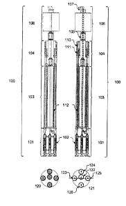
[0012] Figure 1 shows the cross sectional view and the bottom views of an
exemplary embodiment of a drill string that includes a cluster drill of DTH
percussion
hammers;
[0013] Figure 2 shows the cross sectional view and the bottom view of one
embodiment of a drill string for annulus ring hole drilling;
[0014] Figure 3 shows the cross sectional view of one embodiment of the
cluster drill of DTH percussion hammers for annulus ring hole drilling; and
[0015] Figure 4 shows the magnified cross sectional view of the rotary
head
and the special distributor of one embodiment and illustrates the flow of
compressed
air or pressurized fluid from multiple sources.
Detailed Description:
[0016] In the following description, methods and apparatus for
controlling the
operation of cluster drill of down-the-hole (DTH) percussion hammers and the
like are
set forth as preferred examples. The scope of the claims should not be limited
to the
illustrative embodiments but should be given the broadest interpretation
consistent with
the description as a whole.
CA 02803530 2014-11-05
[0017] Referring to the cross sectional view of an exemplary embodiment
of a
drill string 100 as shown in Figure 1. The drill string 100 includes a cluster
drill of
DTH percussion hammers 101, which includes one or more DTH hammers 102
arranged and allocated in either a cylindrical housing or an annulus housing;
one or
more drill pipes 103; a special distributor 104 of compressed air or
pressurized fluid
having one or more rotatable intake swivels, such as 110 and 111 as shown, for
sourcing the compressed air or pressurized fluid; and a rotary head connection
interface 105 for connecting a rotary head 106. In some cases of shallow
drilling, no
drill pipe is necessary.
[0018] The cluster drill of DTH percussion hammers 101 includes one or
more
DTH hammers 102 arranged and allocated in either a cylindrical housing or an
annulus housing. With cylindrical housing, the housing OD defines the diameter
of
the circular hole drilled. With annulus housing, the size of the annulus ring
hole
drilled is determined by the OD and ID of the annulus housing. The cluster
drills of
DTH percussion hammers in cylindrical housing and annulus housing are two
typical
embodiments. The presently claimed invention is applicable to many
modifications
and variations of cluster drill of DTH percussion hammer designs that are
apparent to
the practitioner skilled in the art.
[0019] In accordance to an embodiment of the presently claimed invention,
the
special distributor 104 of compressed air or pressurized fluid comprises one
or more
rotatable intake swivels, such as 110 and 111 as shown, for sourcing the
compressed
air or pressurized fluid. The one or more rotatable intake swivels are
constructed
purposely to allow independent supply of compressed air or pressurized fluid
from
each rotatable swivel to drive the DTH percussion hammers of the cluster
drill. This
is in contrast to the conventional design of using a single centralized supply
source of
compressed air or pressurized fluid to drive all the DTH percussion hammers.
The
CA 02803530 2013-01-30
6
number of rotatable swivels needed depends on the configuration and size of
the
cluster drill of DTH percussion hammers.
[0020] The rotary head 106 provides rotational turning speed and output
torque for the drill string 100. The rotary head 106 is also equipped with an
intake
swivel 107 where compressed air or pressurized fluid is supplied from a
source, which
can be independent of those supplying the special distributor 104 through its
one or
more rotatable intake swivels. The compressed air or pressurized fluid is then
delivered through the internal channel in the rotary head 106 to the internal
channel in
the rotary head connection interface 105. Figure 4 shows the magnified cross
sectional view of the rotary head and the special distributor. Different
sources of
compressed air or pressurized fluid are supplying through the intake swivel
401 of the
rotary head and the rotatable intake swivels 402 and 403 of the special
distributor; and
the compressed air or pressurized fluid travel through separate paths 411,
412, and 413
respectively to the corresponding DTH percussion hammers.
[0021] One or more drill pipes 103 are attached vertically, providing the
extension lengths for the drill string 100 to meet the drill depth
requirement. Internal
delivery pipes 112 are equipped from top to bottom inside each of the drill
pipes 103.
Compressed air or pressurized fluid is delivered through the internal delivery
pipes
112 and reaches the cluster drill of DTH percussion hammers 101. When two
drill
pipes are vertically attached, their respective delivery pipes are internally
aligned and
connected, forming the continuous delivery channels for the compressed air or
pressurized fluid supplied through the rotatable swivels of the special
distributor 104
and the intake swivel of the rotary head 106. Each DTH percussion hammer is
connected to one delivery pipe. The drill pipes 103 also transfer the
rotational torque
from the rotary head 106 to the cluster drill of DTH percussion hammers 101.
In some
cases of shallow drilling, no drill pipe is necessary. In those cases, the
cluster drill of
DTH percussion hammers 101 is directly connected to the special distributor
104.
CA 02803530 2013-01-30
7
[0022] Depending on the requirement of the hole to be drilled, various
allocation arrangements of the drill bits are possible. In the case of annulus
ring hole,
if the difference between the annulus ring hole OD and ID is small, one
circumferential layer of drill bits is used. For an annulus ring hole with a
large OD-ID
difference, two or more circumferential layers of drill bits can be used to
cover the
large annulus ring drilling area. Similarly for drilling large circular holes,
two or more
circumferential layers of drill bits can be used to cover the drilling area.
[0023] Referring to the bottom views 120 and 121 of an exemplary
configuration of a cluster drill of DTH percussion hammers shown in Figure 1,
in
which two circumferential layers of drill bits are arranged from the center of
the
cluster drill of DTH percussion hammers 101 to its outermost diameter as
viewed from
the bottom. The drilling area that can be formed by each drill bit is governed
by the
swept area produced by its revolving motion about the rotational axis of the
cluster
drill of DTH percussion hammers 101. It is common to allocate the drill bits
in cluster
drill in such a way that summation of the drilling area formed by all drill
bits located
at different radial distance from the center of the cluster drill will fully
cover the entire
cluster drill bottom face area.
[0024] Referring to Figure 2. Another exemplary configuration of a
cluster
drill of DTH percussion hammers is shown. As shown by the bottom view 210, one
circumferential layer of drill bits is used in an annulus ring housing for
drilling
annulus ring holes.
[0025] In accordance to an embodiment of presently disclosed invention,
within each circumferential layer of drill bits there is at least one drill
bit's
corresponding DTH percussion hammer is supplied with an independent source of
compressed air or pressurized fluid through one of the rotatable swivels, such
as 110
and 111, of the special distributor 104, or the intake swivel 107 of the
rotary head 106.
[0026] For the exemplary configuration of a cluster drill of DTH
percussion
hammers as shown in Figure 1, since there are two circumferential layers,
there are at
CA 02803530 2013-01-30
8
least two independent supply sources of compressed air or pressurized fluid
and three
rotatable swivels in the special distributor 104. In this exemplary
embodiment, the
inner circumferential layer of drill bits comprises only one drill bit 122.
Its DTH
percussion hammer is supplied with compressed air or pressurized fluid from an
independent supply source through the rotatable swivel 110 of the special
distributor
104. The outer circumferential layer comprises four drill bits 123, 124, 125,
and 126.
The DTH percussion hammer of drill bit 123 is selected to be independently
supplied
with compressed air or pressurized fluid from an independent supply source
through
the rotatable swivel 111 of the special distributor 104. The DTH percussion
hammers
of drill bit 124, 125, and 126 are supplied with compressed air or pressurized
fluid
from a central supply source through the intake swivel of the rotary head.
[0027] In the situation where the drill bit 124, 125, or 126 hit on mixed
ground
formation during drilling and causes direct exhaustion of the compressed air
or
pressurized fluid from the central supply source - direct exhaust phenomenon.
However, since the DTH percussion hammer of drill bit 123 is supplied by an
independent compressed air or pressurized fluid source, it can continue to
hammer and
penetrate the mixed ground. Once more solid rock strata are reached, the
halted DTH
percussion hammers of drill bit 124, 125, or 126 can restart hammering.
[0028] In accordance with various embodiments, specially designed
percussion drill bits with tungsten carbide tips are mounted at the bottom of
each drill
bit. The drill bit has a special peripheral profile to achieve a larger
percussion area on
both the annulus OD and ID drilling areas. The drill bit cutting face profile
is not
necessary circular in shape, and can be triangular, rectangular, or any
special profiled
shape.
[0029] The foregoing description of the present invention has been
provided
for the purposes of illustration and description. It is not intended to be
exhaustive or
to limit the invention to the precise forms disclosed. Many modifications and
variations will be apparent to the practitioner skilled in the art.
CA 02803530 2013-01-30
9
[0030] The
embodiments were chosen and described in order to best explain
the principles of the invention and its practical application, thereby
enabling others
skilled in the art to understand the invention for various embodiments and
with various
modifications that are suited to the particular use contemplated. It is
intended that the
scope of the invention be defined by the following claims and their
equivalence.