Note: Descriptions are shown in the official language in which they were submitted.
CA 02803582 2012-12-20
Mkl. 9: G011139/00
Static Fourier spectrometer.
The claimed invention pertains to interference spectral devices and can be
used
for spectral research in various fields of technology.
Fourier spectrometers are widely used in spectral research due to high
luminosity
(Zhakino gain), high-speed performance and ability of simultaneous
registration of
the entire radiation spectrum of the range under investigation [1]. Fourier
spectrometers comprise the following basic functional units: a system of
forming
an input light beam (hereinafter - an input collimator), an interferometric
unit, a
projective system, a recording device.
In dynamic Fourier spectrometers various modifications of the classic
Michelson
interferometer comprising a semitransparent reflector (a beam splitter) and
two
reflectors (or retroreflectors), one of which is movable and provides variable
optical
path difference are most often used as an interferometric unit. When moving
the
movable reflector periodical illumination alteration takes place in the plane
of
recording, and so modulation of each wavelength of incoming radiation spectrum
occurs, with modulation frequency being in inverse proportion to wavelength.
Metrological parameters of dynamic Fourier spectrometer (e.g. signal-to-noise
ratio) depend on modulation depth, depending in its turn on movement
steadiness
and parallelism of moving the interferometric unit reflectors. When operating
Fourier spectrometers external vibrations influence the steadiness of the
reflectors
movement that limits ability of using dynamic Fourier spectrometers under
conditions of strong vibrations.
The special feature of static Fourier spectrometers is realization of spatial
decomposition of interference image in the plane of recording device along one
of
coordinates. Advantages of static Fourier spectrometers over dynamic ones are
absence of movable structures, linear motors and comparatively complex control
systems that gives opportunity to create compact vibration resistant
spectrometer
and to lower costs in its production. Modulation depth in static Fourier
spectrometers depends on quality of picture transfer that is determined by
frequency and contrast characteristics of the projective system and decreases
with
increase of aberrations in projective system. Decrease of modulation depth
worsens metrological parameters of static Fourier spectrometer (signal-to-
noise
CA 02803582 2012-12-20
2
ratio). Hence improvement of metrological parameters of static Fourier
spectrometers is primarily associated with minimization of losses of
projective
system.
In known static Fourier spectrometers [Patent No.6222627; Patent No. 6930781;
US Patent No.7092101 ] the tasks of image transfer by projective system with
correction of many types of aberrations are constructively solved by
increasing the
number of refracting and reflecting surfaces in an optical system and by using
aspherical surfaces.
In the static Fourier spectrometer according to [Patent No.6222627] an
interferometec unit is produced on the basis of doubly refracting crystal
(referred to
as Wollaston prism according to [Patent No. 6222627]), with a projective
system
including several lenses located sequentially. A multiple-unit diode ruler is
used as
a device of image recording. The main disadvantage of this device is
dependence
of spectrometer optical parameters on material and geometric size of
polarization
crystal used for obtaining an interference image that results in limitations
in
spectral resolution due to dependence of path difference on wavelength.
Another
disadvantage is losses on spherical and chromatic aberrations that are aided
by
sequentially located lenses in the projective system.
In the static Fourier spectrometer according to [Patent No.6930781] a scheme
with
transverse shift of interfering rays is employed as an interferometec unit
(referred
to as San'yak interferometer according to [Patent No.6930781]).
The main disadvantage of this device is technical complexity of qualitative
projection and focusing of image obtained by the interferometric unit of this
type
with minimum light losses. In such case interference image is located on
infinity
that requires realization in the Fourier spectrometer a projective system
comprising optical elements with aspherical surface that reduces
processability in
production and increases cost.
The closest to the claimed invention in the set of significant features is
device [US
Patent No.7092101] in which an interferometric unit comprising a beam splitter
and two reflectors producing an interference image in the plane of one of
reflectors
is realized according to the Michelson interferometer scheme. An input
collimator
optically connected with the interferometric unit consists of a diaphragm and
an
objective. Picture of the indicated interference image is projected on an
image
CA 02803582 2012-12-20
3
recording device by means of a projective system optically connected with the
image recording device.
The main disadvantage of this device when studying radiation of extended
object
is transfer of the interference image picture by the projective system
comprising a
sequence of lens components to the recording device. In this device decrease
of
aberrations is provided due to increase of the number of lenses, that in its
turn
increases the spectrometer dimensions and production costs.
For polychromatic radiation in most of the considered devices the task of
transfer
of interference image picture is solved by projective systems comprising
consecutively located lens components with axial rays path. This results in
losses
of resolving capacity concerned with chromatic and spherical aberrations. When
transferring the interference image picture obtained for extended object
losses
concerned with astigmatism and field curvature appear. This significantly
reduces
the quality of the picture projected on the image recording device and
therefore
worsens metrological parameters of spectrometer. In projective systems
consisting
only of consecutively located lenses technological solutions for simultaneous
compensation of different types of aberrations lead to increase of the number
of
lenses and dimensions resulting in increase of production costs.
The task of this invention is improvement of optical parameters of the
spectrometer in which light losses decrease when transferring picture on
aberrations is attained at the minimum number of optical elements produced
with
reduced costs.
The set task is achieved in that a static Fourier spectrometer contains an
input
collimator optically connected with an interferometric unit comprising a beam
splitter and at least two reflectors installed with the ability to create an
interference
image localized in the reflectors plane, and an image recording device
optically
connected with the interferometric unit by means of a projective system with
the
ability to project the indicated interference image picture on the image
recording
device, with the projective system comprising a spherical reflector and a lens
objective centered relative to the normal line to the optical surface of the
reflector,
with the reflector and the lens objective being made with ability of optical
radiation
to pass through the lens objective from the interferometric unit to the
spherical
CA 02803582 2012-12-20
4
reflector with reflection from it and passing through the same lens objective
to the
recording device.
The suggested set of features of the static Fourier spectrometer allows to
attain
minimum radiation losses with high quality of transfer of the interference
image
picture to the recording device due to elimination of spherical and chromatic
aberrations and astigmatism due to the best combination of minimum number of
optical elements of the projective systems preferably of spherical shape.
In the projective system for correction of chromatic aberrations at
noncomplanarity
of interference image plane and interference image picture plane a composite
lens
objective is used, comprising at least two lenses made of different materials
and
connected by an optical contact, with one of lenses being made planoconvex and
the second lens connected with it being made in the meniscus form.
For providing vibration stability the interferometric unit is made as two
glass
rectangular prisms glued by hypotenuse faces one of which is coated with beam
splitting cover, with the reflectors being made on one of the cathetus
surfaces in
each prism for minimization the number of optical elements, and the prisms
being
glued so that the faces with the reflectors are adjacent faces of the
polyhedron
resulting from the gluing, with one of the prisms of the interferometric unit
being
connected with the lens objective of the projective system by an optical
contact for
providing the equal conditions of rays passage coming from the interferometer
reflecting faces to the spherical reflector and rays coming from the spherical
reflector to the recording device.
The projective system comprises a compensator located between the lens and the
recording device and connected with the lens objective by the optical contact
for
providing vibration stability, with the compensator being made of the same
material that the prisms of the interferometric unit for equality of optical
path
lengths in the compensator and in the interferometric unit.
The compensator is made in the form of isosceles rectangular prism with
reflecting
cover on hypotenuse face for providing portability, with the recording device
being
located perpendicular to the plane of one of the reflecting faces of
polyhedron of
the interferometric unit.
The claimed device is explained by the following drawings:
CA 02803582 2012-12-20
Fig. 1 shows functional scheme of the static Fourier spectrometer (section in
the
plane of the radiation object).
Fig. 2 shows the Fourier spectrometer scheme (section in the plane of the
image
recording device).
5 Fig. 3 shows the static Fourier spectrometer (axonometry).
Fig. 4. shows the interferometric unit of the static Fourier spectrometer.
Fig. 5 shows formation of path difference in the interference unit of the
Fourier
spectrometer.
Fig. 6 shows interfering beams on the plane of interference observation.
Fig. 7 shows rays path in the projective system with correction of chromatic
aberration.
Fig. 8 shows rays path with correction of field aberrations.
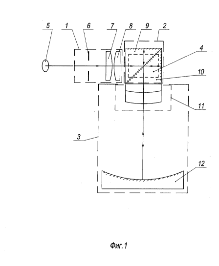
The static Fourier spectrometer according to Fig. 1 - 3 consists of the input
collimator I optically connected with the interferometric unit 2, the
projective
system 3 and the image recording device 4.
The input collimator 1 directs radiation from analyzed object 5 to the
interferometric unit 2. The input collimator may contain a diaphragm and a
system
consisting of several lenses. In this case, to provide uniformity of
reflectors
illumination and minimum required for optical coordination number of scheme
elements it is made in the form of the diaphragm 6 and two lenses 7 and 8. The
interferometric unit 2 can be made of separate reflectors according to the
classic
scheme of the Michelson interferometer. The interferometric unit 2 as shown in
Fig.1 is realized in the form of two rectangular isosceles prisms 9 and 10
made of
the same material (with the same values of refraction index n) and glued in an
effort to increase vibration stability and to minimize production costs.
According to
Fig.2 one of the hypotenuse faces 16 is coated with reflecting cover having
reflective index close to 50% (preferably within the range of 40% to 60% )
with
formation of a beam splitter, with reflecting covers (preferably with
reflective index
of more than 95%) being made on the cathetus surfaces 17 and 18 of each prism
9 and 10. In other versions it's possible to use separate adjustable
reflectors
located in close proximity to cathetus surfaces of the prisms; however
realization
of reflecting covers on the indicated surfaces provides vibration resistance
and
CA 02803582 2012-12-20
6
minimization of production costs. The interferometric unit 2 and the
projective
system 3 are optically coordinated so that directed to the interferometric
unit 2 light
beam divides on the face 16, reflects from the reflecting surfaces 17 and 18
of the
prisms 9 and 10 and then comes to the lens objective 11.
The projective system 3 comprises the spherical reflector 12 enabling to
decrease
light losses in chromatic aberrations, the lens objective 11 (doublet) and the
compensator 13 located as shown in Fig. 3 between the lens objective 11 and
the
image recording device 4. The compensator 13 connected with the lens objective
11 by the optical contact is made of the same material that the prisms 9 and
10 of
the interferometric unit 2.
The recording device 4 is performed in the form of a multi-element receiver
(e.g.
CCD or CMOS) that allows to improve energetic and metrological parameters of
recording, including signal/noise, detection threshold and measurement time.
In
other versions the image recording device 4 can be produced as a scanning
photoreceiver, such as a Vidicon.
The compensator 13 as shown in Fig. 3 is made in the form of rectangular prism
with reflecting cover on the hypotenuse face 19 and is installed on the lens
objective 11 so that light beam reflected from the reflector 12 and passed
back
through the lens objective 11 enters into the first cathetus face of the prism
compensator 13, reflects, and comes from the hypotenuse face to the image
recording device 4. To unify details and to increase assembly processability
the
compensator 13 is made in the form of prism identical to one of the prisms 9
or 10
of the interferometric unit 2, with optical path length in the compensator 13
being
equal to optical path in the prisms 9 and 10 of the interferometric unit 2.
The lens objective 11 as shown in Fig. 2 of the projective system 3 is
connected
by the optical contact with the interferometric unit 2, that increases
vibration
stability of such system and excepts necessity of using adjustable elements in
the
device, providing its portability. The lens objective 11 is made of two
lenses, with
one of lenses being planoconvex 14, and the other 15 being made in meniscus
form and is connected with the first one, with curvature radius of concave
surface
of the lens 15 coinciding with curvature radius of convex surface of the
planoconvex lens 14, that enables to correct spherical aberrations. Lenses 14
and
CA 02803582 2012-12-20
7
15 are made of different glass grades, with differing refraction indexes n for
correction of chromatic aberration of position, with the lens 14 being made of
glass
with a higher refraction index n. Connection of lenses 14 and 15 lowers light
losses on the optical contact surfaces as a result of gluing and simplifies
structural
task of fastening the lens objective 11.
To obtain interference image the prisms 9, 10 of the interferometric unit 2 as
shown in Fig. 4 are turned relative to each other around the axis
perpendicular to
gluing plane on a angle and are glued together so that for passing in the
interferometric unit 2 rays variable optical path difference appears along one
of the
coordinates in the plane of cathetus face, as a result of this interference
image in
the planes of the reflecting surfaces 17 and 18 of the prisms 9 and 10 is
observed
in the form of sequence of dark and light bands. The faces with reflecting
covers
17 and 18 as shown in Fig. 4 are adjacent faces of polyhedron resulting from
the
gluing.
The device operates as follows. Optical radiation from the object under
analysis 5
enters to the static Fourier spectrometer through the input collimator 1
coordinated
with the projective system 3 by aperture. The input collimator converts
radiation
from each point of the object 5 into beam close to parallel one, and directs
the
obtained beam to the interferometric unit 2, providing uniformity of
illumination of
working area of reflecting surfaces of the prisms 9 and 10 of the
interferometric
unit 2. The beam is divided on the beam splitter 16 (Fig. 5). Each part of the
divided beam passes along its path with reflection from the reflecting faces
17 and
18.
Due to variable path difference Al (x) interference of rays and formation of
two-
dimensional interference image in the planes of the reflecting faces 17 and 18
of
the prisms 9 and 10 appear. By means of the projective system 3 optically
coordinated with the input collimator 1 and interferometric unit 2, as well as
by
means of the compensator 13 picture of the obtained interference image is
projected on the image recording device 4.
The spectral resolution of the static Fourier spectrometer is determined by
transfer
quality of interference image and by spatial frequency N of resolved
interference
bands of its picture on the recording device 4 (Fig.6). Path difference Al
depends
CA 02803582 2012-12-20
8
linearly on x coordinate along interference image in the plane of reflecting
surfaces
of the prisms 9 and 10, and also on mutual turn a angle. In small-angle range,
dependence is expressed by formula Al(x) = 2ax, i.e. path difference of rays
Al
increases as turn angle a of the prisms 9 and 10 increases. As shown in Fig. 6
in
each P point of the interference image plane (e.g. the reflecting surface 17
of the
prism 9) for two interfering rays L1 and L2 under a angle to each other
increment
of path difference dal varies from one band to another along the line of
intersection
of the wave surfaces V1 and V2 (the line of intersection of the wave surfaces
is
perpendicular to the plane, Fig. 6). Spatial frequency N of interference bands
for
the fixed linear field of interference for small angles according to formula N
=2a/2
decreases with radiation wavelength . from the object 5 increases and is
determined by a angle at the fixed wavelength X. So on radiation wavelength X
= 1
urn when using the rectangular prisms 9 and 10 with 40 mm hypotenuse face the
value of turn angle a of the prisms relative to each other is approximately 20
angular minutes; with the number of interference bands being 200 in linear
field of
the recording device with dimensions 20 X 20 mm.
Absence of chromatic aberrations of increase is provided by employing a
reflecting
element, i.e. the spherical reflector 12 in composition of the projective
system 3.
Chromatic aberrations of position arising in the case of divergence from
system's
symmetry, e.g. shift of recording plane M'A' in picture as shown in Fig. 7 for
h
distance from plane of interference image MA formation, are corrected by
gluing
the lenses 14 and 15 produced from different glass grades. At the same time
the
lens 14 is made of glass with higher value of refraction index n, than that of
the
lens 15. Rays coming from point A of interference image located in the plane
of
the reflecting face 17 of the prism 9, separate on respective angle 0
depending on
wavelength A. as a result of refraction. After reflection from the spherical
reflector
12 rays pass through the same lens objective 11, as a result compensation of
initial deviation to 0 angle occur. Rays A,1 and X2 gather in A' point of the
image
recording plane. Elimination of chromatic aberration of position provides
better
frequency and contrast characteristic of projective system, and thus better
metrological parameters (resolution, signal-to-noise ratio) of the static
Fourier
spectrometer.
CA 02803582 2012-12-20
9
Monochromatic aberrations correction is provided by optical coordination of
the
interference unit 2 and the projective system 3. Object of transfer is
interference
image generated on reflecting faces of the prisms 9 and 10. Using of the
spherical
reflector 12 in the projective system 3 makes it possible to represent object
located
in the center of its curvature without spherical aberration at any aperture
angles of
beam. Using of the lens objective 11 as a correcting element of optical scheme
of
the projective system 3 provides elimination of aberrations of image field
curvature
in meridional section for interference image points outside optical axis 00,
as
shown in Fig. 8 (e.g. B and B'). Using the composite lens objective 11
comprising
two lenses 14 and 15 with different refraction indexes enables compensation of
noncomplanarity of the reflecting plane 17 and the recording plane 20 M'B',
expressed in h shift. For points of interference image generated in the plane
of the
reflecting surface 17, such solution allows to correct astigmatism arising in
cases
with for point B lying outside optical axis 001. This in its turn increases
image
quality of B' in the recording field 20 M'B'. To unify employed optical
elements and
to ensure compact location the image recording device 4 is located
perpendicularly to the plane of the reflecting surface 17 of the prism 9 and
picture
of interference image is transferred to the recording device 4 by using the
compensator 13.
The claimed invention provides high values of luminosity and modulation index
when obtaining a two-dimensional interference image, transfer of its figure
with
minimum losses at the best combination of minimum number of optical elements
used, due to structural realization of interferometric unit and projective
system
coordinated with compensator, connected into a single module by optical
contact.