Note: Descriptions are shown in the official language in which they were submitted.
CA 02803594 2012-12-20
WO 2011/109437 PCT/US2011/026746
1
ROTATING FOOTBALL GOALPOST AND
METHOD OF RETROFITTING AN EXISTING FOOTBALL GOALPOST
FIELD
[0001 ] The invention generally relates to the field of sporting goal
structures and
apparatus, and more particularly, embodiments of the present invention relate
to a rotatable
football goalpost and method for retrofitting existing football goalposts.
BACKGROUND
[0002] Football is an enormously popular sport in the United States. All
across the
country, playing fields are frequently designed to facilitate football games.
A football field has a
football goalpost located at each end of the playing field. As illustrated in
Figures 2 and 13, a
conventional football goalpost 10 generally has a U-shaped goal defined by a
horizontal crossbar
12 and two vertical uprights 14. The goalpost 10 is usually supported by a
tubular base 16,
generally referred to as a gooseneck, extending up from the ground. Figures 1-
10 and 11(a)-
11(c) illustrate one embodiment of a plate-mounted version of a goalpost 10 in
which the
gooseneck 16 is secured (typically by welding) to a plate 18 that is in turn
mounted on a concrete
foundation 19 as shown in the corresponding Figures. Figures 12-15, 16(a)-
16(c), 17-21, 22(a)-
22(b), 23, and 24(a)-24(b) illustrate an embodiment of another version of a
conventional football
goalpost 10 in which the gooseneck 16 is mounted within a ground sleeve 15
secured within and
partially buried in the ground as shown in the corresponding Figures. Figures
1 and 12 include a
part list and corresponding reference numbers for each part. These reference
numbers are
provided for convenience only and are associated only with the corresponding
Figure 1 or 12,
respectively, and are not used in any other the Figures or in the
specification of this application.
[0003] As illustrated in Figure 1(b), the gooseneck 16 typically is curved
such that the
crossbar 12 and two vertical uprights 14 are positioned approximately 8 to 9
feet from the central
CA 02803594 2012-12-20
WO 2011/109437 PCT/US2011/026746
2
vertical axis 11 of the gooseneck adjacent the ground. In many instances,
however, this
configuration of the gooseneck 16 (and the football goalpost 10 itself,
including, the crossbar 12
and vertical uprights 14) obstructs the ability of athletic facility personnel
to convert a football
field into a field suitable for other sporting events or purposes. This
problem is particularly
apparent when personnel must convert a football field into a soccer field.
Because a soccer field
is substantially the same size as a football field, the football goalposts 10
(which have no use in a
soccer game) tend to be a nuisance. Although football goalposts 10 may be
removed from the
field by removing the goosenecks 16 from the ground sleeves 15 or by
disconnecting the
mounting plates 18 from their concrete foundations 19, the removal process can
be time-
consuming and labor intensive, which can be problematic when soccer and
football games may
be played back-to-back. As a result, and as illustrated in Figure 41,
personnel usually position
each soccer goal 30 directly under each football goalpost 10. Positioned as
such, the upper
crossbar 32 of the soccer goal 30 is usually located only slightly below,
e.g., approximately
twenty-four inches or so below, the crossbar 12 of the football goalpost 10.
This configuration
has many drawbacks. For example, this configuration may make it difficult for
soccer referees
to distinguish between a soccer ball striking the crossbar 12 of the football
goalpost 10 (out of
bounds) and striking the upper crossbar 32 of the soccer goal 30 (in play).
[0004] Accordingly, there is a need to provide a football goalpost that
enables facility
personnel to quickly and easily move or otherwise reconfigure the goalpost
such that the crossbar
12 of the football goalpost 10 is not positioned above or otherwise in the way
of the soccer goal
30, including, without limitation, the upper crossbar 32 of a soccer goal.
CA 02803594 2012-12-20
WO 2011/109437 PCT/US2011/026746
3
BRIEF DESCRIPTION OF THE SEVERAL VIEWS OF THE DRAWINGS
[0005] Having thus described embodiments of the invention in general terms,
reference
will now be made to the accompanying drawings, which are not necessarily drawn
to scale, and
wherein:
[0006] Figures 1-10 and 11(a)-11(c) illustrate the components and installation
of one
embodiment of a plate-mounted version of a conventional football goalpost;
[0007] Figures 12-15, 16(a)-16(c), 17-21, 22(a)-22(b), 23, and 24(a)-24(b)
illustrate the
components and installation of one embodiment of the ground-sleeve-mounted
version of a
conventional football goalpost;
[0008] Figure 25 is a cross-sectional view of the outer tubular member of the
gooseneck
and a cartridge, according to one embodiment of the present invention;
[0009] Figure 26 is a cross-sectional view of the first rotational mechanism
of the
cartridge of Figure 25, according to one embodiment of the present invention;
[0010] Figure 27 is a cross-sectional view of the second rotational mechanism
of the
cartridge of Figure 25, according to one embodiment of the present invention;
[0011 ] Figure 28 is a cross-sectional view of the outer tubular member of the
gooseneck
and a cartridge, according to another embodiment of the present invention;
[0012] Figure 29 is a cross-sectional view of the first rotational mechanism
of the
cartridge of Figure 28, according to another embodiment of the present
invention;
[0013] Figure 30 is a cross-sectional view of the second rotational mechanism
of the
cartridge of Figure 28, according to another embodiment of the present
invention;
CA 02803594 2012-12-20
WO 2011/109437 PCT/US2011/026746
4
[0014] Figures 30(a) is a side-plan view of the shaft of the cartridge of
Figures 25 and 28,
including the dimension thereof and material composition, according to one
embodiment of the
present invention;
[0015] Figures 30(b) is a side plan view of the first portion of the shaft
illustrated in
Figure 30(a);
[0016] Figures 30(c) is a plan view of the first end of the shaft illustrated
in Figure 30(a)
along lines A-A of Figure 30(a);
[0017] Figures 30(d) is a plan view of the second end of the shaft illustrated
in Figure
30(a) along lines B-B of Figure 30(a);
[0018] Figures 31(a) and (b) are side and top plan views of the outer race of
the first
rotational shaft of the cartridge of Figures 25 and 28, including the
dimensions thereof and
material composition, according to one embodiment of the present invention;
[0019] Figures 32(a) and (b) are side- and top-plan views of the inner race of
the first
rotational shaft of the cartridge of Figures 25 and 28, including the
dimensions thereof and
material composition, according to one embodiment of the present invention;
[0020] Figures 33(a) and (b) are side- and top-plan views of the outer race of
the second
rotational shaft of the cartridge of Figures 25 and 28, including the
dimensions thereof and
material composition, according to one embodiment of the present invention;
[0021 ] Figures 34(a) and (b) are side- and top-plan views of the inner race
of the second
rotational shaft of the cartridge of Figures 25 and 28, including the
dimensions thereof and
material composition, according to one embodiment of the present invention;
[0022] Figures 35(a) and (b) are side- and top-plan views of the support band
of the
gooseneck of Figures 25 and 28, including the dimensions thereof and material
composition;
CA 02803594 2012-12-20
WO 2011/109437 PCT/US2011/026746
[0023] Figures 36(a) and (b) are side and top plan views of one embodiment of
the first
clamp ring of the gooseneck, including the dimensions thereof and material
composition,
according to one embodiment of the present invention;
[0024] Figures 37(a) and (b) are side- and top-plan views of the second clamp
ring of the
gooseneck of Figures 25 and 28, including the dimensions thereof and material
composition,
according to one embodiment of the present invention;
[0025] Figures 38(a) and (b) are side- and top-plan views of the end cap or
cap of the
cartridge of Figures 25 and 28, including the dimensions thereof and material
composition,
according to one embodiment of the present invention;
[0026] Figures 39(a) and (b) are side and top plan views of one embodiment of
the
support tube of the cartridge of Figure 28, including the dimensions thereof
and material
composition, according to one embodiment of the present invention;
[0027] Figure 40 illustrates a tool for rotating the second portion of the
outer tubular
member of the gooseneck relative to the first portion of the outer tubular
member, according to
one embodiment of the present invention;
[0028] Figure 41 is a partial-perspective view of a football/soccer field with
a
conventional football goalpost and soccer goalpost arrangement;
[0029] Figures 42(a) and (b) are partial-perspective views of a
football/soccer field with a
football goalpost and soccer goalpost arrangement, according to one embodiment
of the present
invention; and
[0030] Figures 43(a) and (b) are block diagram illustrating the steps in
retrofitting an
existing football goalpost so that the second portion of the outer tubular
member of the
CA 02803594 2012-12-20
WO 2011/109437 PCT/US2011/026746
6
gooseneck relative to the first portion of the outer tubular member, according
to one embodiment
of the present invention.
DETAILED DESCRIPTION OF EMBODIMENTS OF THE INVENTION
[0031 ] Embodiments of the present invention now will be described more fully
hereinafter with reference to the accompanying drawings, in which some, but
not all,
embodiments of the invention are shown. Indeed, the invention may be embodied
in many
different forms and should not be construed as limited to the embodiments set
forth herein;
rather, these embodiments are provided so that this disclosure will satisfy
applicable legal
requirements. Like numbers refer to like elements throughout.
[0032] As used herein and in the claims, the term "ground" refers to the
surface of the
earth, but also refers other natural or manmade surfaces including, for
example, manmade floors
in a building. For example, where the present application describes a plate 18
or ground sleeve
15 as being anchored in the ground, the post or sleeve may be anchored in the
dirt of a field,
concrete, a floor in a building, or other material or surface suitable for
anchoring the post or
sleeve, including, without limitation, foundations for artificial turf.
[0033] Referring to the drawings, and in particular, to Figures 42(a) and (b),
in
accordance with one embodiment of the present invention, there is illustrated
a football goalpost
20 having a gooseneck 26 in which at least a portion of the gooseneck can be
rotated to move the
crossbar 22 and uprights 24 to a location where they will not significantly or
materially interfere
with a soccer goal 30 or field 31. In one embodiment, the portion of the
gooseneck 26 of the
football goalpost 20 is rotatable about a substantially vertical axis defined
by the center of the
relatively straight portion of the gooseneck 26 extending upwardly from where
the gooseneck is
mounted to or secured in the ground (either via the plate 18 or ground sleeve
15, respectively, as
CA 02803594 2012-12-20
WO 2011/109437 PCT/US2011/026746
7
discussed above). According to the present invention, the rotation of the
goalpost 20 may be
unrestricted, i.e., 360 degree rotation in either direction; restricted 360
degree rotation in a
particular direction (i.e., clockwise or counter-clockwise direction);
restricted rotation to a
limited angle between 0 degrees and 360 degrees in either direction (e.g., 180
degrees); or
restricted rotation to a limited angle between 0 degrees and 360 degrees in a
particular direction
(e.g., 180 degrees in a clockwise or counter-clockwise direction).
[0034] More particularly, Figure 42(b) illustrates how a football field may be
converted
to a soccer field by positioning a soccer goal 30 in front of the football
goalpost 20, wherein the
football goalpost has a gooseneck 26 that can be rotated to move the crossbar
18 to a location
where it will not significantly or materially interfere with a soccer goal 30
or field 31. Positioned
as such, the crossbar 22 and the uprights 24 are located well behind the end
line 33 of the field
31 where they will not materially or significantly interfere with the soccer
goal 30 and field. As
described in detail below, embodiments of the present invention provide a
rotating football
goalpost 20 that allows a user to easily rotate the rotatable portion of the
gooseneck 26 of the
goalpost. In one embodiment, the user must apply approximately one hundred
(100) ft/lbs of
torque (or twenty-five (25) lbs thrust at a four (4) foot distance from the
central axis of the
gooseneck 26) or less. The present invention also provides a method for
retrofitting an existing
football goalpost 10 (as illustrated in Figure 41) such that the gooseneck of
the existing goalpost
becomes rotatable. Embodiments of the rotating football goalpost 20 further
allow a user to
make adjustments in the vertical and rotational alignment of the football
goalpost after
installation.
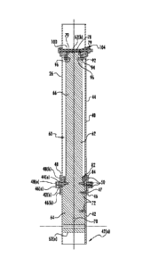
[0035] Referring to Figure 25, there is shown a portion of the gooseneck 26 of
a football
goal post 20, according to one embodiment of the present invention. The
gooseneck 22
CA 02803594 2012-12-20
WO 2011/109437 PCT/US2011/026746
8
comprises an outer tubular member 40 having a first portion 42 and a second
portion 44. The
first portion 42 of the outer tubular member 40 has a first end 42(a) and a
second end 42(b).
The second portion 44 of the outer tubular member 40 has a first end 44(a) and
a second end
44(b). The second end 44(b) of the second portion 44 of the outer tubular
member 40 is attached
to the cross bar 22 of the goalpost 20 and the uprights 24 extend from the
cross bar, as is known
in the art and as is disclosed in Figures 1 and 13. The first end 42(a) of the
first portion 42 of the
outer tubular member 40 is secured to a mounting structure, such as the plate-
mounting structure
illustrated in Figures 1-10 and 11(a)-1 l (c) or the ground-sleeve-mounting
structure illustrated in
Figures 12-15, 16(a)-16(c), 17-21, 22(a)-22(b), 23, and 24(a)-24(b), both of
which are well
known in art.
[0036] The second end 42(b) of the first portion 42 of the outer tubular
member 40
releasably engages the first end 44(a) of the second portion 44 of the outer
tubular member 40
such that the second portion of the outer tubular member is structured to
rotate relative to the
first portion of the outer tubular member. In one embodiment, as illustrated
in Figures 25 and
26, the rotating football goalpost 20 includes a first clamp ring 46 and
second clamp ring 48.
The first clamp ring 46 is positioned about the second end 42(b) of the first
portion 42 of the
outer tubular member 40. The second clamp ring 48 is positioned about the
first end 44(a) of
the second portion 44 of the outer tubular member 40. As discussed more fully
below, the first
and second clamp rings 46, 48 are structured to be releasably engaged to one
another such that in
a first state the clamp rings (and the first and second portions 42, 44 of the
outer tubular member
40) are non-rotatable relative to one another and in a second state the clamp
rings (and the first
and second portions 42, 44 of the outer tubular member 40) are rotatable
relative to one another.
CA 02803594 2012-12-20
WO 2011/109437 PCT/US2011/026746
9
[0037] The first and second clamp rings 46, 48 each comprise a flange 46(a),
48(a) and a
cylindrical portion 46(b), 48(b), both of which have an inner diameter
approximately equal to,
but slightly greater than, the outer diameter of the outer tubular member 40
of the gooseneck 26
such that the first and second clamp rings can be positioned on the second end
42(b) of the first
portion 42 of the outer tubular member 40 and the first end 44(a) of the
second portion 44 of the
outer tubular member 40, respectively. Preferably the fit between the first
and second clamp
rings 46, 48 on the second end 42(b) of the first portion 42 of the outer
tubular member 40 and
the first end 44(a) of the second portion 44 of the outer tubular member 40,
respectively, is
relatively tight. The first clamp ring 46 is secured to the second end 42(b)
of the first portion 42
of the outer tubular member 40 and the second clamp ring 48 is secured to the
first end 44(a) of
the second portion 44 of the outer tubular member by welding and/or using
mechanical fasteners.
In one embodiment, as illustrated in Figures 26, 36(a) and (b), and 37(a) and
(b), the first clamp
ring 46 is secured to the second end 42(b) of the first portion 42 of the
outer tubular member 40
and the second clamp ring 48 is secured to the first end 44(a) of the second
portion 44 of the
outer tubular member by one or more set screws 50, each through a
corresponding aperture 47 in
the first and second clamp rings. In addition to securing the first clamp ring
46 to the second end
42(b) of the first portion 42 of the outer tubular member 40 and the second
clamp ring 48 to the
first end 44(a) of the second portion 44, the set screws 50 in the flanges
46(a), 48(a) of the first
and second clamp rings also can be used to stiffen and adjust the position of
the first and second
portions 42, 44 of the corresponding outer tubular member 40. As illustrated
in Figure 26, the
set screws 50 extending through the apertures 47 in the cylindrical portions
46(b), 48(b) of the
first and second clamp rings 46, 48 preferably extend into corresponding
apertures that are pre-
drilled in the first and second portions 42, 44 of the outer tubular member
40, respectively.
CA 02803594 2012-12-20
WO 2011/109437 PCT/US2011/026746
[0038] As discussed above, the first and second clamp rings 46, 48 are
structured to be
releasably engaged to one another such that in a first state the clamp rings
(and first and second
portions 42, 44 of the outer tubular member 40) are non-rotatable relative to
one another and in a
second state the clamp rings (and first and second portions 42, 44 of the
outer tubular member)
are rotatable relative to one another. As illustrated in Figures 26, 36(a) and
(b), and 37(a) and
(b), the first clamp ring 46 and the second clamp ring 48 each include one or
more apertures 52
that are structured to receive either a threaded or non-threaded bolt. In the
embodiment
illustrated Figures 36(a) and (b) and 37(a) and (b), apertures 52(a) are
threaded and structured to
receive a threaded bolt whereas apertures 52(b) are unthreaded and structured
to receive a
shoulder bolt. In another embodiment of the present invention, one or more of
apertures 52(b)
can be structured to receive the shackle of a padlock (not shown) so that the
first and second
clamp rings 46, 48 can be locked together in the non-rotatable first state for
safety and security
purposes to prevent unauthorized rotation of the second portion 44 of the
outer tubular member
40 relative to the first portion 42 of the outer tubular member. Preferably,
the aperture(s) 52(b)
are sized to be approximate to, but slightly greater than the diameter of the
shackle to avoid
wearing the inside of the aperture(s). The apertures 52(b) may be provided
with bronze bushings
(not shown) that can be replaced in the event of wear.
[0039] Figures 36(a) and (b) and 37(a) and (b) disclose dimensions for the
first and
second clamp rings 46, 48, according to one embodiment of the present
invention. The first and
second clamp rings 46, 48 are preferably formed of metal by casting or
machining from stock
material, or another material having substantial rigidity and strength.
According to the
embodiments illustrated in Figures 36(a) and (b) and 37(a) and (b), the first
and second clamp
CA 02803594 2012-12-20
WO 2011/109437 PCT/US2011/026746
11
rings 46, 48 the first and second clamp rings 46, 48 are formed of either 6061-
T6 aluminum or
304 stainless steel.
[0040] When the first and second the clamp rings 46, 48 are locked in the
first state
(whether by a threaded or unthreaded bolt or the shackle of a lock, or a
combination thereof) and
are non-rotatable relative to one another, the first and second clamp rings
provide support to the
gooseneck 26 by securing the second end 42(a) of the second portion of the
outer tubular
member 40 and the first end 44(a) of the second portion 44 of the outer
tubular member together.
[0041 ] In one embodiment, the first and second the clamp rings 46, 48 are
preferably is
covered with padding or an elastomeric material to prevent or mitigate injury
should an athlete
fall on or collide with the gooseneck 26.
[0042] Referring again to Figure 25, rotation of the second portion 44 of the
outer tubular
member 40 relative to the first portion 42 of the outer tubular member is
accomplished through a
cartridge 60. As illustrated in Figures 25 and Figures 30(a), (b), (c), and
(d), the cartridge 60
comprises at least a shaft 62, a first rotation mechanism 80, and a second
rotation mechanism 90.
The shaft 62 has first and second ends 62(a), 62(b). The shaft 62 defines a
first portion 64 and a
second portion 66 wherein the diameter of the first portion 64 of the shaft is
greater than the
diameter of the second portion 66 of the shaft. The shaft 62 further defines a
tapered portion 68
between the first portion 64 of the shaft and the second portion 66 of the
shaft.
[0043] The shaft 62 can be constructed of hollow tubular members and/or of
solid tubular
members. Preferably the shaft 62 is constructed of metal or another material
having substantial
rigidity and strength, as the shaft must bear a substantial portion of the
weight and shear forces
generated by the gooseneck 26, cross bar 22 and uprights 24. The first portion
64, second
portion 66 and tapered portion 68 of the shaft 62 can be separately formed
components that are
CA 02803594 2012-12-20
WO 2011/109437 PCT/US2011/026746
12
secured together by welding or mechanical fasteners or, alternatively, two or
more of these
components can be cast together as a unitary piece or machined from stock
material. In the
embodiment illustrated in Figures 25 and Figures 30(a), (b), (c), and (d), the
shaft 62 comprises a
solid, unitary piece of 6061-T6 aluminum.
[0044] The shaft 62 can be secured to the first portion 42 of the outer
tubular member 40
by welding or using mechanical fasteners. As illustrated in Figures 25 and
Figures 30(a), (b),
and (c), the shaft 62 can included apertures 70 structured to receive the
bolts shown in Figures 15
and 16(c) that secure the gooseneck 26 to the upper portion of the ground
sleeve 15. For plate-
mounted versions of the goalpost 20, apertures 70 are not necessary.
Additional, as illustrated in
Figure 25, the shaft 62 and the first portion 42 of the outer tubular member
40 can be further
secured together using set screws 72. In one embodiment, the set screws 72 are
provided in pairs
that are vertically spaced. There can be one or more pairs of these set screws
72. For purposes
of example and not limitation, there can be two (2) sets of set screws 72,
each set having one (1)
pair, that are spaced 90 degrees or 180 degrees apart or four (4) sets, each
set having one (1) pair,
that are spaced 90 degrees apart.
[0045] As illustrated in Figures 25 and 26, the first rotation mechanism 80 is
positioned
about the first portion 64 of the shaft 62 adjacent the tapered portion 68 and
near the junction of
the first portion 42 of the outer tubular member 40 and the second portion 44
of the outer tubular
member. The first rotation mechanism 80 comprises a radial and thrust load
bearing structured
to support the weight and shear load generated by the gooseneck 26, cross bar
22 and uprights
24, while at the same time enabling the second portion 44 of the outer tubular
member 40 to
rotate relative to the first portion 42 of the outer tubular member. The first
rotation mechanism
CA 02803594 2012-12-20
WO 2011/109437 PCT/US2011/026746
13
80 can comprise a ball or roller bearing and, preferably, comprise a helical
roller bearing,
spherical-roller bearing or tapered roller bearing.
[0046] In an alternate embodiment, as illustrated in Figures 26, 31(a) and (b)
and 32(a)
and (b), the first rotation mechanism 80 comprises an outer race 82 formed of
304 stainless steel
and an inner race 84 formed of bearing bronze. Other bearing materials, such
as nylon, may
alternatively be used between the shaft 62 and the second portion 44 of the
outer tubular
member. As illustrated in Figure 26, the shaft 62 includes a shoulder or
notched area 74 on
which the inner race 84 is seated. The inner race 84 can be secured to the
shaft 62 by welding or
using mechanical fasteners. As illustrated in Figures 26 and 30(a), the inner
race 84 is secured to
the shaft 62 by a pair of set screws 86 that are screwed through corresponding
apertures 86(a) in
the inner race and into apertures 86(b) in the shaft and that are spaced 180
degrees apart. Four
(4) set screws 86 at 90 degrees apart can be used as well. As illustrated in
Figures 32(a) and (b),
the inner race 84 has a substantially cylindrical configuration with an inner
diameter
approximately equal to, but slightly larger than, the outer diameter of the
second portion 66 of
the shaft 62.
[0047] As illustrated in Figures 26, 31(a) and (b), the outer race 82 has an L-
shaped
configuration comprising a base 82(a) and a flange 82(b) extending therefrom.
The base 82(a)
and flange 82(b) define a shoulder or notched area 83 having a width
approximately equal to the
thickness of the inner race 84 such that the outer race 82 is structured to be
slidably seated on the
inner race. As illustrated in Figures 31(a) and (b), the base 82(a) has a
substantially cylindrical
configuration with an inner diameter approximately equal to, but slightly
larger than, the outer
diameter of the second portion 66 of the shaft 62 and the flange 82(b) has a
substantially
cylindrical configuration with an inner diameter approximately equal to, but
slightly larger than,
CA 02803594 2012-12-20
WO 2011/109437 PCT/US2011/026746
14
the outer diameter of the inner race 84. The outer diameter of the base 82(a)
and a flange 82(b)
are the same and are approximately equal to, but slightly smaller than, the
inner diameter of the
second portion 44 of the outer tubular member 40 to ensure a relatively tight
fit between the
outer race 82 and the interior of the second portion 44 of the outer tubular
member.
[0048] Referring to Figure 26, in one embodiment, the set screws 50 extending
through
the apertures 47 in the cylindrical portion 48(b) of the second clamp ring 48
may extend through
the corresponding apertures pre-drilled in the second portion 44 of the outer
tubular member 40
so that the set screws are in contact with the outer race 82 to secure the
outer race to the second
portion 44 of the outer tubular member. In one embodiment, the outer race 82
defines apertures
that receive the ends of the set screws and, in other embodiments, the ends
just contact the outer
surface of the base 82(a).
[0049] As illustrated in Figures 25 and 27, the second rotation mechanism 90
is
positioned about the second end 62(b) of the shaft 62. The second rotation
mechanism 90
comprises a radial and thrust load bearing structured to support the weight
and shear load
generated by the gooseneck 26, cross bar 22 and uprights 24, while at the same
time enabling the
second portion 44 of the outer tubular member 40 to rotate relative to the
first portion 42 of the
outer tubular member. The second rotation mechanism 90 can comprise a ball or
roller bearing
and, preferably, comprise a helical roller bearing, spherical-roller bearing
or tapered roller
bearing.
[0050] In an alternate embodiment, as illustrated in Figure 26, 33(a) and (b)
and 34(a)
and (b), the second rotation mechanism 90 comprises an outer race 92 formed of
304 stainless
steel and an inner race 94 formed of bearing bronze. Other bearing materials,
such as nylon, may
alternatively be used between the shaft 62 and the second portion 44 of the
outer tubular member
CA 02803594 2012-12-20
WO 2011/109437 PCT/US2011/026746
40. As illustrated in Figures 26 and 30(a), the second end 62(b) of the shaft
62 defines a
shoulder or notched area 76 having a reduced diameter on which the inner race
94 is seated. The
inner race 94 can be secured to the shaft 62 by welding or using mechanical
fasteners. As
illustrated in Figures 26 and 30(a), the inner race 94 is secured to the shaft
62 by a pair of set
screws 96 that are screwed through corresponding apertures 96(a) in the inner
race and into
apertures 96(b) in the shaft and that are spaced 180 degrees apart. Four (4)
set screws 96 at 90
degrees apart can be used as well. As illustrated in Figures 34(a) and (b),
the inner race 94 has a
substantially cylindrical configuration with an inner diameter approximately
equal to, but slightly
larger than, the outer diameter of the second end 62(b) of the shaft 62 at the
shoulder or notched
area 76.
[0051] As illustrated in Figure 26 and Figures 33(a) and (b), the outer race
92 has an L-
shaped configuration comprising a base 92(a) and a flange 92(b) extending
therefrom. The base
92(a) and flange 92(b) define a shoulder or notched area 93 having a width
approximately equal
to the thickness of the inner race 94 such that the outer race 92 is
structured to be slidably seated
on the inner race. As illustrated in Figures 33(a) and (b), the base 92(a) has
a substantially
cylindrical configuration with an inner diameter approximately equal to, but
slightly larger than,
the outer diameter of the second end 62(b) of the shaft 62 at the shoulder or
notched area 76 and
the flange 92(b) has a substantially cylindrical configuration with an inner
diameter
approximately equal to, but slightly larger than, the outer diameter of the
inner race 94. The
outer diameter of the base 92(a) and a flange 92(b) are the same and are
approximately equal to,
but slightly smaller than, the inner diameter of the second portion 44 of the
outer tubular member
40 to ensure a relatively tight fit between the outer race 92 and the interior
of the second portion
44 of the outer tubular member.
CA 02803594 2012-12-20
WO 2011/109437 PCT/US2011/026746
16
[0052] Referring to Figures 27 and 35(a) and (b), in one embodiment, the set
screws
extending through the apertures 1087 in the support band 104 may extend
through the
corresponding apertures pre-drilled in the second portion 44 of the outer
tubular member 40 so
that the set screws are in contact with the outer race 92 to secure the outer
race to the second
portion 44 of the outer tubular member. In one embodiment, the outer race 92
defines apertures
that receive the ends of the set screws and, in other embodiments, the ends
just contact the outer
surface of the base 92(a).
[0053] The first rotation mechanism 80 and the second rotation mechanism 92
cooperate
to allow the second portion 44 of the outer tubular member 40 of the gooseneck
26 (including the
cross bar 22 and the uprights 24) to rotate relative to the first portion 42
of the outer tubular
member and the shaft 62 when the first and second clamp rings 46, 48 are in
the second state
(i.e., are not secured together). More specifically, the outer race 82 of the
first rotation
mechanism 80 and the outer race 92 of the second rotation mechanism 90 slide
upon the inner
race 84 of the first rotation mechanism and the inner race 94 of the second
rotation mechanism,
respectively, to allow the second portion 44 of the outer tubular member 40 of
the gooseneck 26
(including the cross bar 22 and the uprights 24) to rotate relative to the
first portion 42 of the
outer tubular member, the shaft 62, the inner race 84 of the first rotation
mechanism and the
inner race 94 of the second rotation mechanism.
[0054] Referring to Figures 25, 27, 30(a) and (d), and 38 (a) and (b), the
cartridge 60 may
also include an end cap or cap 78. As illustrated in Figure 27, the outer race
92 of the second
rotation mechanism includes a shoulder or notched area 95 structured to
slidably receive the cap
78. The cap 78 may be attached to the second end 62(b) of the shaft 62 by
welding or using
mechanical fasteners. As illustrated in Figures 30(a) and (d) and 38 (a) and
(b), the cap 78 is
CA 02803594 2012-12-20
WO 2011/109437 PCT/US2011/026746
17
attached to the second end 62(b) of the shaft 62 using four (4) screws 79
received in apertures
79(a) of the shaft 62 and 79(b) of the end cap. The purpose of the cap 78 is
to slidably secure
and retain the outer race 92 to, and as part of, the cartridge 60 during
installation of the cartridge
into the outer tubular member 40. In an alternate embodiment (not shown), the
exterior of the
upper edge of the second end 62(b) of the shaft 62 may be notched so as to
receive a snap or
shrink-fitted ring made of metal, nylon or another synthetic material and that
is structure to
slidably retain the outer race 92 against the inner race 94 during
installation of the cartridge 60
into the outer tubular member 40.
Referring to Figures 28, 29, and 30, in one embodiment, the cartridge 60 may
also
include a support tube 104 positioned inside the outer tubular member 40 and
outside at least a
portion of the shaft 62. The support tube 104 extends from the first rotation
mechanism 80 to the
second rotation mechanism 90. The purpose of the support tube 104 is to
provide stiffen and
provide additional support to the second portion 44 of the outer tubular
member 40.
[0055] Referring to Figure 27, the second portion 44 of the outer tubular
member 40 of
the gooseneck 26 may further include an end member 100 structured to
distribute the weight and
shear load generated by the gooseneck 26, cross bar 22 and uprights 24 to the
outer race 92 of the
second rotational mechanism 90. As illustrated in Figure 27, the outer tubular
member 40
comprises a pair of apertures 102 positioned between the first end 44(a) and
the second end
44(b) of the second portion 44 of the outer tubular member. The end member 100
is structured
to extend through the pair of apertures 102 in the second portion 44 of the
outer tubular member
40 and to be in contact with the second rotation mechanism 90 and, more
specifically, the outer
race 92 of the second rotation mechanism, to at least partially transfer the
weight and shear load
generated by the gooseneck 26, cross bar 22 and uprights 24 to the second
rotation mechanism.
CA 02803594 2012-12-20
WO 2011/109437 PCT/US2011/026746
18
In one embodiment, the end member 100 is structured to be in slidable contact
with the end cap
78, if one is used, or the second end 62(b) of the shaft 62, if no end cap is
used, to at least
partially transfer the weight and shear load generated by the gooseneck 26,
cross bar 22 and
uprights 24 to the shaft. As illustrated in Figure 27, the end member 100 may
comprise a bolt
extending through the second portion 44 of the outer tubular member 40 secured
using a nut (or a
nut and washer).
[0056] According to one embodiment, as illustrated in Figures 27 and 35(a) and
(b), the
gooseneck 26 may further include a support band 104 positioned about the
second portion 44 of
the outer tubular member 40 where the end member 100 is inserted. The support
band 104 has a
substantially cylindrical configuration with an inner diameter approximately
equal to, but slightly
larger than, the outer diameter of the outer tubular member 40. The support
band 104 has a pair
of apertures 106 structured to receive the end member 100 and that correspond
to apertures 102
in the second portion 44 of the outer tubular member 40. The support band 104
may also include
threaded apertures 108 structured to receive a set screws (not shown) to
further secure the
support band to the second portion 44 of the outer tubular member 40. These
set screws may
extend through corresponding apertures pre-drilled into in the second portion
44 of the outer
tubular member 40. As illustrated in Figure 35(b), the support band 104
includes three apertures
108 spaced at approximately 120 degree increments. Other spacing
configurations may be used.
The purpose of the support band 104 is to provide additional support to the
outer tubular member
40 where the end member 100 is inserted, as the apertures 102 may create
stress concentrations
in the outer tubular member 40 and areas potentially subject to fatigue.
[0057] Referring to Figures 40(a) and (b), there is illustrated a tool 110
that can be used
to rotate the second portion 44 of the outer tubular member 40 relative to the
first portion 42 of
CA 02803594 2012-12-20
WO 2011/109437 PCT/US2011/026746
19
the outer tubular member. The tool 110 comprises a handle 112 (that may
include an elastomeric
grip), an engagement member 114, and an engagement recess 116. The length of
the handle 112
may vary, but it has been determined that a handle of approximately four (4)
feet provides
sufficient leverage to reduce the required force to rotate the second portion
44 of the outer
tubular member 40 relative to the first portion 42 to approximately twenty-
five (25) lbs (i.e., one
hundred (100) ft/lbs of total torque or twenty-five (25) lbs at a distance of
four (4) feet). The
handle has first and second ends 112(a) and (b). The first end 112 of the
handle 112 may include
a ribbed surface or may be covered at least partially with an elastomeric
material or cover having
a ribbed surface or other raised areas to provide sufficient friction for the
user to firmly grip the
handle.
[0058] The engagement member 114 extends from the second end 112(b) of the
handle
112 and is attached to the handle by welding, using mechanical fasteners or a
bracket and
mechanical fasteners. The engagement member 114 is configured to have a
curvature that is
substantially the same as the curvature of the outer tubular member 40, if no
support band 104 is
used, or the curvature of the support band, if one is used. The length of the
engagement member
114 can vary, but preferably the length is such that the engagement member
extends at least 90
degrees and, more preferably, 180 degrees, around the outer tubular member 40,
if no support
band 104 is used, or around the support band, if one is used. The engagement
member 114
preferably is covered with padding or an elastomeric material to prevent
scratching or marring of
the surface of the outer tubular member 40, if no support band 104 is used, or
support band, if
one is used, as scratches may result in rusting or discoloration. The
engagement member 114 has
first and second ends 114(a), 114(b). The first end 114(a) of the engagement
member defines an
engagement recess 116, which is configured to matingly engage the head of the
end member
CA 02803594 2012-12-20
WO 2011/109437 PCT/US2011/026746
100, or the nut securing the end member, similar to a socket of a socket
wrench. The
engagement recess 116 may comprise either a recessed area (like a socket of a
socket wrench) or
an aperture extending through the first end 114(a) of the engagement member
114.
[0059] The tool 110 may be constructed of a variety of materials. In one
embodiment,
the tool 110 is constructed of aluminum or another relatively strong, but
lightweight metal.
[0060] To use the tool 110, the head of the end member 100 (or the nut
securing the
engagement member) is positioned inside the engagement recess 116 and then the
tool is pivoted
so that the second end 114(b) of the engagement member 114 is urged toward and
in contact
with the surface of the outer tubular member 40, if no support band 104 is
used, or the surface of
the support band, if one is used. In this position, the handle will extend
beyond the side of the
gooseneck 26. The user will then push the handle 112 of the tool 110 in a
manner to push the
second end 114 of the engagement member 114 against the outer tubular member
40, if no
support band 104 is used, or the surface of the support band, if one is used.
If the gooseneck 26
is configured for rotation only in a particular direction, the tool must be
oriented such that the
user is pushing in the required direction.
The present invention also provides a method for retrofitting the gooseneck 16
of an
existing football goalpost 10, as illustrated in Figure 41, so that the
gooseneck 16 is converted
into a rotatable gooseneck 26. According to one embodiment, as illustrated in
Figures 43(a) and
(b), the method comprises providing a gooseneck comprising a tubular outer
member. See Block
120. The provision of the gooseneck will likely include removing the football
goalpost 10 from
its mounting structure, which may comprise removing the gooseneck 16 from the
ground sleeve
15 or decoupling the plate 18 from the concrete foundation 19. The outer
tubular member is
then cut into a first portion and a second portion, each of the first and
second portions of the
CA 02803594 2012-12-20
WO 2011/109437 PCT/US2011/026746
21
tubular outer member comprising first and second ends. See Block 122. A
cartridge is then
provided. See Block 124. In one embodiment, the cartridge comprises a shaft
having first and
second ends, the shaft defining a first portion and a second portion wherein
the diameter of the
first portion of the shaft is greater than the diameter of the second portion
of the shaft, the shaft
defining a tapered portion between the first portion of the shaft and the
second portion of the
shaft. The cartridge further comprises first and second rotation mechanisms,
the first rotation
mechanism positioned about the second portion of the shaft adjacent the
tapered portion, the
second rotation mechanism positioned about the second end of the shaft. In one
embodiment, a
support tube positioned outside at least a portion of the shaft, the support
tube extending from the
first rotation mechanism to the second rotation mechanism. The cartridge is
then inserted into
the first portion of the outer tubular member and the second portion of the
outer tubular member
such that the shaft extends at least partially into the first portion of the
outer tubular member and
extends at least partially into the second portion of the outer tubular member
such that the first
end of the shaft is located inside the first portion of the outer tubular
member and the second end
of the shaft is located inside the second portion of the outer tubular member
and the first rotation
mechanism is adjacent the second end of the first portion of the outer tubular
member and the
first end of the second portion of the outer tubular member. See Block 126.
The shaft is then
secured to the first portion of the outer tubular member and wherein the first
and second rotation
mechanisms of the cartridge are structured so that the second portion of the
outer tubular
member is rotatable relative to the first portion of the outer tubular member
and about the shaft.
See Block 128.
In one embodiment, first and second clamp rings are attached to the outer
tubular
member, the first clamp ring positioned about the second end of the first
portion of the outer
CA 02803594 2012-12-20
WO 2011/109437 PCT/US2011/026746
22
tubular member, the second clamp ring positioned about the first end of the
second portion of the
outer tubular member, the clamp rings structured to be releasably engaged to
one another such
that in a first state the clamp rings are non-rotatable relative to one
another and in a second state
the clamp rings are rotatable relative to one another and wherein the first
and second rotation
mechanisms of the cartridge are structured so that when the clamp rings are in
the second state,
the second portion of the outer tubular member is rotatable relative to the
first portion of the
outer tubular member and about the shaft. See Block 130. In one embodiment,
forming a pair of
apertures in the second portion of the outer tubular member and inserting an
end member into the
apertures in the second portion of the outer tubular member, wherein the end
member is in
contact with the second rotation mechanism. See Block 132.
[0061 ] Specific embodiments of the invention are described herein. Many
modifications
and other embodiments of the invention set forth herein will come to mind to
one skilled in the
art to which the invention pertains having the benefit of the teachings
presented in the foregoing
descriptions and the associated drawings. Therefore, it is to be understood
that the invention is
not to be limited to the specific embodiments disclosed and that modifications
and other
embodiments and combinations of embodiments are intended to be included within
the scope of
the appended claims. Although specific terms are employed herein, they are
used in a generic
and descriptive sense only and not for purposes of limitation.