Note: Descriptions are shown in the official language in which they were submitted.
CA 02804065 2012-12-28
DEVICE FOR TRANSPORTING CONTAINERS
BACKGROUND OF THE INVENTION
[0001 ] The present invention relates to a device for transporting containers
having a container
support that can be moved in a transport direction.
[0002] Containers or trays are typically transported through packaging plants
with the aid of
conveyors, belts or chains. In so doing, conveyor belts can flexibly transport
different forms of
containers by means of frictional engagement, whereas chains ensure an exact
control and
positioning of the containers by means of a positive-locking arrangement.
[0003] A particular point to consider is that the containers when empty are
for the most part very
light and consist of a thin easily malleable material, so that only small
forces can be exerted on
said containers. The container material is also for the most part very smooth
so that only a small
frictional force can be utilized.
[0004] The problem with belts is that the mostly very light trays can be
easily shifted. This often
occurs when loading the trays with a product; thus requiring the current
position of each tray to
be reacquired after each loading process, for example, by means of a vision
system. Trays can
also, however, totally unexpectedly shift their position at any time as a
result of, for example, a
draft, vibrations etc. In addition, any inclined container transport as is,
e.g., necessary for creating
packages having narrow products standing side by side (on edge packaging
style) cannot be
implemented using a belt. Due to the small amount of friction between tray and
belt, the trays in
this case would slide from the belt under the force of gravity.
[0005] The aforementioned problems can be avoided with the aid of a chain,
which transports the
containers by means of a positive-locking arrangement. The chain, however, has
a rigid pitch so
that changing to another container size is only possible after complicated
reconfiguration or
I
CA 02804065 2012-12-28
restructuring thereof. For the most part, irregularly formed trays can in no
way be directly
inserted onto a chain but require an adapter, a specially adapted carrier
piece, which likewise
must be adapted to each container size. The complex mechanical construction
having many
corners and joints tends to collect dirt and does not lend itself to
applications, which require a
complete and frequent cleaning in order to avoid a contamination of the
products, e.g. with
germs. In order to increase flexibility, chains can be equipped with
entrainment members capable
of being lowered; however, costs, complexity as well as the aforementioned
disadvantages
accordingly increase.
[0006] There are approaches, which bypass the problems of belts by increasing
friction, e.g., by
using a vacuum belt. This is, however, not cost effective in the case of pick-
and-place packaging
plants, which include conveying sections comprising many meters of length, due
to the large
vacuum demand.
[0007] In addition, not all containers have a continuous supporting surface,
which leads to
considerable losses in vacuum.
[0008] The use of vacuum belts for holding containers is associated with large
costs for
maintaining a sufficient vacuum, a high noise level and considerable energy
costs. To ensure
compliance with hygiene guidelines, the use of vacuum belts furthermore
requires an increase in
cleaning work, which has corresponding additional costs.
[0009] Alternative transport systems, as, e.g., walking beam transport
systems, in which the
containers are transported in a stepwise manner by means of beams that raise
and lower, are
likewise mechanically very complex. Systems of this kind are also often
equipped with vacuum
in order to safely carry the containers.
[0010] A further conveyor principle is, e.g., demonstrated by the BOSCH
Rexroth Varioflow
System. In this case, the containers are so tightly clamped that they are held
against gravitational
2
CA 02804065 2012-12-28
force. The clamping elements are moved and the clamped container is thus
transported. Only
very stable containers can be moved in this way because large clamping forces
are required. The
entire transport work is performed by the clamping elements being moved. This
conveyor
principle cannot be used for the transport of thin, easily malleable trays,
which are typically used
in packaging plants.
SUMMARY OF THE INVENTION
[0011 ] The aim underlying the invention is to provide a transport system for
containers,
particularly for trays and boxes, for a packaging plant, which combines the
flexibility of a belt
system with the high degree of reliability of a chain conveyance. A shifting
of the containers is
particularly to be prevented so that an initially ascertained position of a
container in relation to
the transport system is maintained during the entire pass through the
packaging plant. In addition,
the transport system is to be capable of use in applications, which require
the containers to be
inclined at an angle with respect to the direction of transport. The system is
to be easy to clean
and cost-effectively produced.
[0012] In order to meet the aim according to the invention, a first and a
second lateral transport
guide for guiding the containers on both sides are associated with the belt-
shaped container
support in a device of the kind mentioned at the beginning of the application.
At least one of the
transport guides can be moved in the transport direction at the same speed as
the container
support, and the transport guides have clamping elements for fixing the
containers between the
first and the second transport guides.
[0013] The required high degree of flexibility requires a conveyance device,
which transports the
containers substantially by means of frictional engagement. Because said
containers in the loaded
state are very heavy in comparison to the inherent rigidity thereof, it may be
necessary to support
the same across the total container surface. For that reason, a conveyor belt
is preferably used, on
which the container rests with the entire bottom surface thereof. Such a
conveyor belt offers a
3
CA 02804065 2012-12-28
degree of flexibility and good support and furthermore has good cleaning
features.
[0014] The fixing of the containers results from an additional lateral
clamping. Because said
clamping only prevents the containers from shifting and does not support the
same, it can be very
much weaker than, for example, is the case in the Rexroth Varioflow system.
The result of said
clamping is that the relative position of said containers to the conveyor belt
does not change
again during conveyance.
[0015] Two opposing clamping elements which move with the container are
required to achieve
the necessary clamping. Said elements have to both move exactly at the same
speed--typically at
the speed of the conveyor belt--so that the containers do not start to rotate
even on long
conveyance sections. In the event that a rotation said containers is desired,
this can be achieved
by a targeted change in the speeds of the clamping elements.
[0016] The container support is preferably a conveyor revolving in a conveying
plane, for
example a plate, chain or vibration conveyor, and the clamping elements are
preferably designed
to introduce a clamping force in a clamping plane which, e.g., is
substantially parallel to the
conveying plane.
[0017] The clamping elements associated with the lateral transport guides are
preferably located
opposite one another, and said clamping elements are designed as lateral guide
elements.
[0018] One of the lateral transport guides can be connected to the belt-shaped
container support.
The clamping elements of the lateral transport guide can be fixedly connected
in the shape of
cams to said belt-shaped container support.
[0019] At least one of the lateral transport guides can preferably be driven
individually.
[0020] At least one of the lateral transport guides is preferably equipped
with flexible, resilient
4
CA 02804065 2012-12-28
clamping elements.
[0021 ] The flexible clamping elements are preferably adjusted to the
container such that they
reliably fix said container, however with as little force as possible, by
means of clamping. In
addition, said container may not be lifted off of the container support. This
means that the
introduction of the clamping force has to occur preferably horizontally or
that is to say in a
clamping plane parallel to the container support. In order to achieve this
end, clamping elements
are required where needed, which are adapted to each type of container, very
resilient and can be
easily switched when necessary.
[0022] At least one of the transport guides can be arranged inclined against
the conveying plane
so as to press the containers against the container support, i.e. slightly
downward sloping in the
transport direction. In so doing, a slippage of the clamping elements would
continuously occur in
a downward direction, whereby the containers are pressed against said
container support.
[0023] The second clamping element required for fixing the containers can
typically be used for
all types of containers because it does not have to be resiliently
constructed.
[0024] The lateral transport guide equipped with resilient clamping elements
can be laterally
displaceable transversely to the transport direction. By changing the distance
of the guide
elements to one another--e.g. by the resilient transport guide or that is to
say the resilient
clamping element being arranged in a displaceable manner--the system can be
simply adapted to
different container widths.
[0025] The lateral transport guide equipped with resilient clamping elements
can be embodied as
a looped belt.
[0026] The resilient clamping elements can be embodied as lips.
CA 02804065 2012-12-28
[0027] The resilient clamping elements can also be embodied as coated toothed
belts, for
example toothed belts having Super Grip® coating. Processed coatings such
as, e.g.,
Linaplus® are also conceivable. Vertical spikes can also, e.g., be
introduced into the coating
as resilient elements.
[0028] The resilient clamping elements can also be embodied as individual
"plastic springs" on a
transport element.
[0029] In order to align the containers, at least one of the transport guides
can run at an acute
angle with respect to the other transport guide on an entry section. At the
end of the entry section,
at least one stop bar which can be pivoted in the conveying plane is provided
as a stop for the
containers
[0030] In order to save on cost and space, the clamping elements can be
resiliently configured on
only one side of a container. A rigid stop is introduced on the other side.
This stop offers the
advantage of a straight stop surface, which allows for an exact positioning of
the containers. Said
stop can most simply be moved at the same speed as the conveyor system by
attaching it directly
to the same. In order to facilitate the deflection around the conveyor drums,
the stop can be
vertically incised or said stop comprises totally independent segments, which
are so narrow that
they can be guided around the deflection radius of the conveyor belt. Cams,
which are welded
onto the belt, are, for example, are well suited in this case for their normal
use as entrainment
members.
[0031 ] The conveyor belt and the resilient lateral guides are driven at
exactly the same speed in
order to prevent the containers from shifting. In this case, the speed of the
conveyor belt can, for
example, be acquired as the master speed by means of an encoder. This speed
signal then
controls the actuation of the lateral guide, which must occur without
slippage.
[0032] The resilient element must be selected such that it exerts a reliable
clamping force on the
6
CA 02804065 2012-12-28
container without, for example, lifting said container due to an unfavorable
direction of force or
deforming said container due to too great of a clamping force. Because the
containers are made
from thin, relatively instable plastic or cardboard, a high degree of
resiliency is required in order
to ensure the necessary clamping force without inadmissibly high fluctuations.
Said resiliency
must especially be present in instances when tolerances exist in container
width or when said
containers assume slightly different orientations during clamping. In
addition, the resilient
element must be embodied such that it can be deflected via conveyor drums.
First of all, this
requires the elements to be adapted to the respective containers.
[0033] Evidence has shown that a profile comprising loop cleats is
particularly capable of
clamping a plurality of different containers. In order to prevent products
from shifting on the belt,
these very resilient belts are typically used as gentle conveyor belts for
fruit.
[0034] To ensure a reliable conveyance of the containers, the profile
comprising loop cleats must
be configured such that at least three loops clamp the container.
[0035] As an alternative, a resilient clamping element can be used while
exploiting the flexural
weakness of said element when it is inclined at an angle. The ideal angle
between clamping
element and a perpendicular to the conveyor belt lies preferably between 15-
20°. Besides
optimal accessibility from above, an ideal force direction is also ensured at
this angle.
[0036] This clamping element can, for example, be cost effectively produced as
a belt such that a
belt webbing is fastened as a resilient lip to a V-notch applied as the basic
element to a toothed
belt.
[0037] Alternatively the option exists here to directly apply the lip to the
toothed belt and thereby
to maintain an inclined position, which might be required in this case, by
means of a rotation of
the drive belt during transport.
7
CA 02804065 2012-12-28
[0038] In addition, coatings as resilient elements are conceivable. This has
cost advantages
because many coatings are standardly available (e.g. Supergrip®). A
processing of a soft
coating material, e.g., as unstable prisms is also conceivable. This form
provides a type of
self-cleaning effect in the deflections as well as small deflection radii.
[0039] When selecting the resilient element, the following applies:
[0040] A looped belt is preferred for unstable containers with large contact
surfaces, which are
transverse to the direction of motion. Loops have the advantage of smaller
contact pressing
forces.
[0041 ] In the case of narrow containers, which are transversely conveyed, a
resilient profile
inclined at about 15° or coated toothed belts are more suitable because
loops can cant;
thus allowing the container to rotate.
[0042] The conveyor belt should primarily carry the containers with very small
frictional
engagement. In this way, the positioning and clamping of the containers
between the lateral guide
elements is disturbed as minimally as possible.
[0043] It should be further noted that the lateral guides can also be
partially used. The containers
are for the most part sufficiently fixed by the product weight as soon several
products have been
inserted.
[0044] When circulating on the conveyor belt, the guide elements can be
cleaned by means of
scrapers, brushes or if required a "wash station". The operation is thereby
not compromised by a
gradual collection of dust and dirt.
[0045] The advantages which result with the device according to the invention
include among
other things:
8
CA 02804065 2012-12-28
[0046] reliable transport of the containers without shifting
[0047] hence camera systems are not required to detect the container position
prior to each
packaging stage
[0048] no relative movement--no cosmetic damage
[0049] good sanitation, easy to clean
[0050] simple adaptation to different container sizes and shapes
[0051 ] even irregularly shaped containers can be conveyed without additional
carrier elements
[0052] up to now a very complicated conveyance system was required for
cardboard boxes with
attached covers and for tall containers
[0053] may be also be used for transporting containers which are inclined at
an angle
[0054] simple, cost-effective design
BRIEF DESCRIPTION OF THE DRAWINGS
[0055] Additional advantages, features and details of the invention become
evident in the
following description of preferred exemplary embodiments as well as with the
aid of the
drawings, which serve merely to explain said invention and are not meant to
limit the
interpretation thereof. The drawings schematically show in
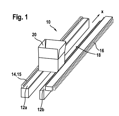
[0056] FIG. I an oblique view of a conveying device for containers;
9
CA 02804065 2012-12-28
[0057] FIG. 2 the top view of a conveying device with laterally clamped
containers;
[0058] FIG. 3 an oblique view of a conveying device with laterally clamped
containers;
[0059] FIGS. 4-6 a cross-sectional view of clamping elements adapted to
different container
[0060] (a) shapes;
[0061 ] FIG. 7 mode of operation of a clamping element;
[0062] FIG. 8 a further arrangement of a clamping element in cross section
[0063] FIG. 9 a cross-sectional view through a toothed belt having a lip
attached thereto;
[0064] FIG. 10 the arrangement of the toothed belt in FIG. 9 inclined at an
angle;
[0065] FIG. 11 an oblique view of an endless conveyor belt having loop-shaped
clamping
elements;
[0066] FIG. 12 the top view of an entry section of a conveying device.
DETAILED DESCRIPTION
[0067] A conveying device 10 shown in FIG. 1 comprises a belt-shaped container
support 12 that
can be moved in a transport direction x and lateral transport guides 14, 16
disposed on each side
of the container support 12. In the example shown, said container support 12
comprises two
conveyor belts 12a, 12b disposed parallel to one another and running
synchronously at the same
speed. A first lateral transport guide 14 consists in this case of a plurality
of cams 15 fixedly
connected to one of the conveyor belts 12a and used as stop elements for
containers 20 which are
CA 02804065 2012-12-28
supported on the container support 12 or that is to say the conveyor belts
12a, 12b and in the
example shown are configured as boxes. The second lateral transport guide 16
is configured as a
revolving belt having clamping elements configured in the shape of resilient
loops (FIG. 11). The
profile comprising loop cleats is designed for reliable conveyance in such a
way that at least three
loops 19 clamp the container 20.
[0068] In the arrangement shown in FIG. 1, the loops 19 are only resiliently
deformed when the
containers 20 are clamped between the fixed cams 15 on the first lateral
transport guide 14 and
said resilient loops19. The first lateral transport guide 14 comprising the
cams 15 serves as a
straight stop surface and thereby facilitates an exact positioning of the
containers 20.
[0069] In the arrangement shown in FIG. 2, both lateral transport guides 14,
16 are resiliently
equipped or rather equipped with resilient clamping elements 18. The
containers 20 are in this
case held on both sides between resiliently deformed clamping elements 18.
[0070] FIG. 3 shows an arrangement having a single conveyor belt serving as
the container
support 12. The container 20 is in this case a basin-like tray as is used, for
example, in the
packaging of biscuits. As in the arrangement shown in FIG. 1, a first lateral
transport guide also
comprises in this instance a plurality of cams 15 fixedly connected to the
conveyor belt and
serving as stop elements for the containers 20. The second lateral transport
guide 16 is a
revolving belt having clamping elements which are not defined in detail.
[0071 ] In FIGS. 4-6, different embodiments of clamping elements 18a, 18b, 18c
are depicted.
These are essentially configured in such a way that besides exerting a
clamping force directed
parallel to the container support 12, they press the containers 20 against
said container support
12; thus ensuring the required frictional engagement between container 20 and
container support
12 for a reliable conveyance of the light, empty containers.
[0072] A clamping element suitable for thin-walled, light containers 20 is
depicted in FIGS. 7
11
CA 02804065 2012-12-28
and 8. The clamping element 18 consists of a toothed belt 24 as the basic
element having a
v-shaped profile, on which a belt webbing 28 is fastened as a resilient lip.
[0073] An alternative embodiment is depicted in FIG. 9. The lip is applied in
this case directly to
the toothed belt. An inclined position of the lip 28, which might be required
here, can, for
example, be achieved by a rotation of the toothed belt 24 during conveyance
(FIG. 10).
[0074] Particularly rectangular containers are initially transferred to the
conveyor belt by a
destacker, which is not shown. In so doing, the destackers allow the
containers to fall onto the
conveyor belt in an uncontrolled manner. When entering the conveyance section
and particularly
between the lateral clamping devices, the containers have to be aligned,
otherwise said containers
would be clamped in a slanted or skewed fashion.
[0075] As shown in FIG. 12, one of the lateral transport guides 14, 16--in
this instance the
second transport guide 16 comprising the resilient clamping elements 18--is
initially disposed
obliquely along an entry section for the purpose of aligning the containers
20. This disposal
enables said containers 20 to be pushed in the direction of the first lateral
transport guide 14
comprising the fixed stop elements. In addition, this action can be assisted
by a system of
pivoting stop bars 22, which also simultaneously establish a defined distance
between said
containers 20.
[0076] Irregular containers, which do not have a defined preferred
orientation, can also be
accepted by using large tolerances in the positioning thereof and are then
further transported in
this manner. A camera system at the beginning of the conveyance route detects
the orientation,
with which the container is transported. Said orientation does not change
during the conveyance
as a result of clamping.
REFERENCE NUMERAL LIST
12
CA 02804065 2012-12-28
[0077] 10 conveying device [0078] 12,12a,b container support, conveyor belts
[0079] 14 first
lateral transport guide [0080] 15 cams on 14 [0081] 16 second lateral
transport guide [0082] 18
clamping elements [0083] 19 profile comprising loop cleats [0084] 20 container
[0085] 22 stop
bar [0086] 23 toothed belt [0087] 24 V-shaped profile [0088] 28 belt webbing,
lip [0089] x
transport direction
13