Note: Descriptions are shown in the official language in which they were submitted.
CA 2804109 2017-05-30
H8322701 CA
SYSTEM FOR MONITORING ELECTRICAL POWER USAGE OF A STRUCTURE
AND METHOD OF SAME
[0001]
FIELD OF THE INVENTION
[0002] This invention relates generally to apparatuses, devices, systems,
and methods for
monitoring electrical power, and relates more particularly to such
apparatuses, devices,
systems, and methods that monitor electrical power in one or more main
electrical power
lines at an electrical circuit breaker panel of a structure.
DESCRIPTION OF THE BACKGROUND
[0003] A structure can have one or more main electrical power lines that
supply the
electrical power to electrical devices (i.e., the load) in the structure. The
main electrical
power lines enter the structure through an electrical circuit breaker panel.
An electrical
circuit breaker panel is the main electrical distribution point for
electricity in a structure.
Electrical circuit breaker panels also provide protection from over-currents
that could cause a
fire or damage to electrical devices in the structure. Electrical circuit
breaker panels can have
three main power lines and use a split-phase electrical power distribution
system.
[0004] Different manufacturers of electrical circuit breaker panels,
including, for
example, Square-D, Eaton, Cutler-Hammer, General Electric, Siemens, and
Murray, have
chosen different conductor spacing and configurations for their electrical
circuit breaker
panels. Furthermore, each manufacturer makes many different configurations of
electrical
circuit breaker panels for indoor installation, outdoor installation, and for
different total
amperage ratings, of which 100 amperes (A) and 200 A service are the most
common in new
construction.
[0005] The different conductor layouts in the many different types of
electrical circuit
breaker panels result in different magnetic field profiles at the metal
surfaces of the electrical
circuit breaker panels. Moreover, the layout of the internal conductors is not
visible without
opening the breaker panel and the manner in which the internal conductor
layout translates
into a magnetic field profile at the surface of the electrical circuit breaker
panel requires a
detailed knowledge of electromagnetic theory to interpret and model correctly.
It is,
CA 02804109 2012-12-28
WO 2012/003494 PCT/US2011/042877
therefore, difficult to accurately measure the magnetic field of the one or
more main electrical
power lines at a surface of the electrical circuit breaker panel.
[0006] Accordingly, a need or potential for benefit exists for an
apparatus, system, and/or
method that allows a non-electrician to accurately determine the magnetic
field of the one or
more main electrical power lines at a surface of the electrical circuit
breaker panel.
BRIEF DESCRIPTION OF THE DRAWINGS
[0007] To facilitate further description of the embodiments, the following
drawings are
provided in which:
[0008] FIG. 1 illustrates a view of an exemplary electrical power
monitoring system
coupled to an electrical circuit breaker panel, according to a first
embodiment;
[0009] FIG. 2 illustrates a block diagram of the electrical power
monitoring system of
FIG. 1, according to the first embodiment;
[0010] FIG. 3 is a graph illustrating the induced voltage versus conductor
current for an
exemplary electrical circuit breaker panel with a metal panel overlying the
main electrical
power lines, according to an embodiment;
[0011] FIG. 4 is a graph illustrating the induced voltage versus conductor
current for an
exemplary electrical circuit breaker panel with a cardboard panel overlying
the main
electrical power lines, according to an embodiment;
[0012] FIG. 5 is a three-dimensional graph illustrating the measured
voltage when a
magnetic field sensor is moved horizontally over an electrical conductor and
at different
heights above the electrical conductor when a steel plate is placed between
the electrical
conductor and the magnetic field sensor, according to an embodiment;
[0013] FIG. 6 is a three-dimensional graph illustrating the measured
voltage when a
magnetic field sensor is moved horizontally over an electrical conductor and
at different
heights above the electrical conductor, according to an embodiment;
[0014] FIG. 7 illustrates exemplary magnetic field sensors located over a
surface of the
electrical circuit breaker panel of FIG. 1, according to the first embodiment;
[0015] FIG. 8 is a graph illustrating a phase angle of a received sign
relative to the
voltage versus a position measured using the magnetic fields sensors of FIG.
7, according an
embodiment;
[0016] FIG. 9 illustrates exemplary magnetic field sensors of electrical
power monitoring
system located over a surface of the electrical circuit breaker panel of FIG.
1, according to an
embodiment different from FIG. 7;
2
CA 02804109 2012-12-28
WO 2012/003494 PCT/US2011/042877
[0017] FIG. 10 illustrates exemplary magnetic field sensors of an
electrical power
monitoring system located on a surface of the electrical circuit breaker panel
of FIG. 1,
according to an embodiment different from FIGs. 7 and 9;
[0018] FIG. 11 illustrates exemplary magnetic field sensors of an
electrical power
monitoring system located on a surface of the electrical circuit breaker panel
of FIG. 1,
according to an embodiment different from FIGs. 7, 9, and 10;
[0019] FIG. 12 illustrates an exemplary magnetic field sensors of an
electrical power
monitoring system located on a surface of the electrical circuit breaker panel
of FIG. 1,
according to an embodiment different from FIGs. 7 and 9-11;
[0020] FIG. 13 is a graph illustrating the induced voltage versus conductor
current for an
exemplary electrical circuit breaker panel with a metal panel overlying the
main electrical
power lines, according to an embodiment;
[0021] FIG. 14 is a graph illustrating a phase angle of a received sign
relative to the
voltage versus a position measured using the electrical power monitoring
system of FIG. 12,
according an embodiment;
[0022] FIG. 15 illustrates a graph showing the actual and predicted current
measurements
of an electrical power monitoring system with a vertically mounted coiled
conductor but
without a magnet, according to an embodiment;
[0023] FIG. 16 illustrates a graph showing the actual and predicted current
measurements
of the electrical power monitoring system of FIG. 12, according to an
embodiment;
[0024] FIG. 17 illustrates an exemplary coiled conductor of an electrical
power
monitoring system located on a surface of the electrical circuit breaker panel
of FIG. 1,
according to an embodiment different from FIGs. 7 and 9-12;
[0025] FIG. 18 illustrates an exemplary magnetic field sensor of an
electrical power
monitoring system located on a surface of panel of the electrical circuit
breaker panel of FIG.
1, according to an embodiment different from FIGs. 7, 9-12, and 17;
[0026] FIG. 19 is a graph illustrating phase angle of a received sign
relative to the voltage
versus position measured using the electrical power monitoring system of FIG.
18, according
an embodiment;
[0027] FIG. 20 illustrates a flow chart for an embodiment of a method of
providing a
system for monitoring electrical power usage of a structure, according to an
embodiment;
[0028] FIG. 21 illustrates a flow chart for an embodiment of an activity of
providing a
sensing device, according to the embodiment of FIG. 20; and
3
CA 02804109 2012-12-28
WO 2012/003494 PCT/US2011/042877
[0029] FIG. 22 illustrates a flow chart for an embodiment of a method of
using a system
for monitoring electrical power usage of a structure, according to an
embodiment.
[0030] For simplicity and clarity of illustration, the drawing figures
illustrate the general
manner of construction, and descriptions and details of well-known features
and techniques
may be omitted to avoid unnecessarily obscuring the invention. Additionally,
elements in the
drawing figures are not necessarily drawn to scale. For example, the
dimensions of some of
the elements in the figures may be exaggerated relative to other elements to
help improve
understanding of embodiments of the present invention. The same reference
numerals in
different figures denote the same elements.
[0031] The terms "first," "second," "third," "fourth," and the like in the
description and
in the claims, if any, are used for distinguishing between similar elements
and not necessarily
for describing a particular sequential or chronological order. It is to be
understood that the
terms so used are interchangeable under appropriate circumstances such that
the
embodiments described herein are, for example, capable of operation in
sequences other than
those illustrated or otherwise described herein. Furthermore, the terms
"include," and
"have," and any variations thereof, are intended to cover a non-exclusive
inclusion, such that
a process, method, system, article, device, or apparatus that comprises a list
of elements is not
necessarily limited to those elements, but may include other elements not
expressly listed or
inherent to such process, method, system, article, device, or apparatus.
[0032] The terms "left," "right," "front," "back," "top," "bottom," "over,"
"under," and
the like in the description and in the claims, if any, are used for
descriptive purposes and not
necessarily for describing permanent relative positions. It is to be
understood that the terms
so used are interchangeable under appropriate circumstances such that the
embodiments of
the invention described herein are, for example, capable of operation in other
orientations
than those illustrated or otherwise described herein.
[0033] The terms "couple," "coupled," "couples," "coupling," and the like
should be
broadly understood and refer to connecting two or more elements or signals,
electrically,
mechanically and/or otherwise. Two or more electrical elements may be
electrically coupled
but not be mechanically or otherwise coupled; two or more mechanical elements
may be
mechanically coupled, but not be electrically or otherwise coupled; two or
more electrical
elements may be mechanically coupled, but not be electrically or otherwise
coupled.
Coupling may be for any length of time, e.g., permanent or semi-permanent or
only for an
instant.
4
CA 02804109 2012-12-28
WO 2012/003494 PCT/US2011/042877
[0034] "Electrical coupling" and the like should be broadly understood and
include
coupling involving any electrical signal, whether a power signal, a data
signal, and/or other
types or combinations of electrical signals. "Mechanical coupling" and the
like should be
broadly understood and include mechanical coupling of all types.
[0035] The absence of the word "removably," "removable," and the like near
the word
"coupled," and the like does not mean that the coupling, etc. in question is
or is not
removable.
DETAILED DESCRIPTION OF EXAMPLES OF EMBODIMENTS
[0036] Some embodiments can teach a system for monitoring usage of
electrical power
by a structure. The structure can have one or more main electrical power lines
that supply the
electrical power to a first load in the structure. A portion of the one or
more main electrical
power lines can run substantially parallel to a first axis. The structure can
further have a
panel that overlies the portion of the one or more main electrical power
lines. The system can
include: (a) a current sensor unit configured to be coupled to a portion of a
surface of the
panel, the current sensor unit having: (a) at least one magnetic field sensor
having a length
substantially parallel to a second axis, wherein the second axis is
substantially perpendicular
to the first axis, and the at least one magnetic field sensor is configured to
detect a magnetic
field generated by the one or more main electrical power lines; and (b) a
processing unit
configured to run on a processor. The current sensor unit can be configured to
produce an
output signal based on the magnetic field detected by the at least one
magnetic field sensor.
The processing unit further can be configured to receive the output signal
from the current
sensor unit and process the output signal to determine one or more parameters
related to the
usage of the electrical power by the first load in the structure.
[0037] Other embodiments can teach an apparatus for measuring electrical
current in one
or more main electrical power lines of a structure. The structure can have a
breaker box. The
breaker box can include at least a first part of the one or more main
electrical power lines and
a metal panel over the first part of the one or more main electrical power
lines. The apparatus
can include: (a) a sensing device having: (1) one or more electrical current
sensors configured
to provide two or more current measurements; and (2) one or more magnets
coupled to the
one or more electrical current sensors; and (b) a processing module configured
to run on a
computational unit and configured to use the two or more current measurements
to determine
the electrical current in the one or more main electrical power lines.
CA 02804109 2012-12-28
WO 2012/003494 PCT/US2011/042877
[0038] Yet other embodiments can disclose a method for providing a system
for
monitoring usage of electrical power of a structure. The structure can have
one or more main
electrical power lines that supply the electrical power to a first load in the
structure. The one
or more main electrical power lines at least partially can run substantially
parallel to a first
axis. The structure can further having a panel that overlies at least part of
the one or more
main electrical power lines. The method can include: providing a current
sensor unit
configured to be coupled to a surface of the panel, the current sensor unit
configured to
produce an output signal based on a magnetic field generated by the one or
more main
electrical power lines; and providing a processing unit configured to receive
the output signal
from the current sensor unit and further configured to process the output
signal to determine
one or more parameters related to the usage of the electrical power of the
structure.
Providing the current sensor unit can include: providing at least one magnetic
field sensor
with a length along a second axis, wherein the at least one magnetic field
sensor is configured
to detect the magnetic field generated by the one or more main electrical
power lines; and
mounting the at least one magnetic field sensor at the current sensor unit
such that the second
axis of the at least one magnetic field sensor is substantially perpendicular
to the first axis
when the current sensor unit is coupled to the surface of the panel.
[0039] Still further embodiments disclose a method for monitoring usage of
electrical
power of a structure using an electrical power monitoring system. The
structure can have one
or more main electrical power lines that supply the electrical power to a
first load in the
structure. The method can include: calibrating the electrical power monitoring
system, a first
raw current in the one or more main electrical power lines and first
calibration data are
generated while calibrating the electrical power monitor system; storing the
first calibration
data and a measurement of the first raw current; measuring a second raw
current; performing
a first recalibration of the electrical power monitoring system if the second
raw current is not
within a predetermined amount of the first raw current; if the second raw
current is within the
predetermined amount of the first raw current, calculating the first measured
current using the
first calibration data; and displaying the first measured current. Performing
the first
recalibration of the electrical power monitoring system can include:
calibrating the electrical
power monitoring system, a third raw current in the one or more main
electrical power lines
and second calibration data are generated while performing the first
recalibration of the
electrical power monitor system; storing the second calibration data and a
measurement of
the third raw current; and calculating a first measured current using the
second calibration
data.
6
CA 02804109 2012-12-28
WO 2012/003494 PCT/US2011/042877
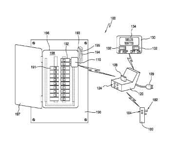
[0040] FIG. 1 illustrates a view of an exemplary electrical power
monitoring system 100
coupled to an electrical breaker panel 190, according to a first embodiment.
FIG. 2 illustrates
a block diagram of electrical power monitoring system 100, according to the
first
embodiment. Electrical power monitoring system 100 can also be considered a
system for
monitoring electrical power usage of a structure. Electrical power monitoring
system 100 is
merely exemplary and is not limited to the embodiments presented herein.
Electrical power
monitoring system 100 can be employed in many different embodiments or
examples not
specifically depicted or described herein. In some examples, electrical power
monitoring
system 100 can include: (a) a sensing device 110; (b) a computational unit
120; (c) a display
device 130; and (d) a calibration device 180.
[0041] Also as shown in FIG. 1, a conventional breaker box or circuit
breaker panel 190
can include: (a) two or more individual circuit breakers 191; (b) two or more
main circuit
breakers 192; (c) main electrical power lines 193, 194, and 195; (d) a panel
196 with an
exterior surface 198; and (e) a door 197 that provides access to circuit
breakers 191 and 192.
[0042] Main electrical power lines 193, 194, and 195 are electrically
coupled to main
circuit breakers 192 and supply the electrical power to electrical devices
(i.e., the load) in the
structure. Panel 196 overlies at least part of main electrical power lines
193, 194, and 195
and associated circuitry to protect people from inadvertently contacting these
energized
conductors. Usually, panel 196 comprises steel or another metal.
[0043] System 100 can determine the load current in main electrical power
lines 193,
194, and 195 by positioning sensing device 110 at surface 198 of panel 196 and
measuring
the induced voltage in sensing device 110. Electrical power monitoring system
100 can use
the measured induced voltage to calculate the electrical current and
electrical power in main
electrical power lines 193, 194, and 195.
[0044] It is possible to place sensing device 110 anywhere on surface 198
of panel 196
and accurately determine the current in each of the individual braches
(including reactive
loads). However, to obtain accurate current measurements requires that the
magnetic fields
from main electrical power lines 193, 194, and 195 to see the same reactance
from panel 196
and sensing device 110. If the reactance is not the same, it becomes more
difficult to
accurately calculate the electrical current and electrical power in main
electrical power lines
193, 194, and 195.
[0045] Another potential limitation of measuring the magnetic field created
by main
electrical power lines 193, 194, and 195 using a sensor unit over panel 196 is
that the metal in
panel 196 can cause the induced voltage to vary non-linearly with the amount
of current
7
CA 02804109 2012-12-28
WO 2012/003494 PCT/US2011/042877
passing through main electrical power lines 193, 194, and 195. Furthermore,
the non-
linearity of the permeability of the metal of panel 196 can vary from position
to position
across panel 196. FIG. 3 is a graph 300 illustrating the induced voltage
versus conductor
current for an exemplary electrical circuit breaker panel with a metal panel
overlying the
main electrical power lines. FIG. 4 is a graph 400 illustrating the induced
voltage versus
conductor current for an exemplary electrical circuit breaker panel where the
metal panel has
replaced with a cardboard panel.
[0046] Similarly, FIG. 5 is a three-dimensional graph 500 illustrating the
voltage
measured using a magnetic field sensor moved horizontally over an electrical
conductor (x-
axis) and at different heights above the conductor (y-axis) when a steel plate
is placed
between the conductor and the magnetic field sensor. FIG. 6 is a three-
dimensional graph
600 illustrating the voltage measured using a magnetic field sensor moved
horizontally over
an electrical conductor (x-axis) and at different heights above the conductor
(y-axis) without
a steel plate between the conductor and the magnetic field sensor. As
illustrated in FIGs. 2-6,
the use of a metal panel overlying the main electrical power lines (i.e.,
panel 196 (FIG. I))
compared to the use of non-magnetic material (i.e., cardboard) or no material
causes a
significant non-linearity of the measure voltage on the surface of the panel
opposite the main
electrical power lines. Furthermore, as shown in FIGs. 5 and 6, this non-
linearity in position
dependent. That is, the amount of the non-linearity varies based on the
position of the sensor
on the steel panel. As will be described below, electrical power monitoring
system 100 can
compensate or eliminate the non-linearity is the induced voltage in sensing
device 110 caused
by the use of metal in panel 196. Moreover, electrical power monitoring system
100 can
ensure that main electrical power lines 193, 194, and 195 see the same
reactance from panel
196 and sensing device 110.
[0047] Referring again to FIG. 2, sensing device 110 can include: (a) two
or more
electrical current sensors or magnetic field sensors 211 and 212; (b) a
controller 213; (c) a
user communications module 214; (d) a transceiver 215; (e) a power source 216;
and (f) a
coupling mechanism 219. Controller 213 can be used to control magnetic field
sensors 211
and 212, user communications module 214, transceiver 215 and power source 216.
In some
embodiments, sensing device 110 can include two, four, six, or eight magnetic
field sensors.
In various examples, magnetic field sensors 211 and 212 can be 2.5 millimeters
(mm) to 12.7
mm in diameter.
[0048] In various examples, sensing device 110 can be configured to be
coupled to
surface 198 (FIG. 1) of panel 196 (FIG. 2) using coupling mechanism 219. In
some
8
CA 02804109 2012-12-28
WO 2012/003494 PCT/US2011/042877
examples, coupling mechanism 219 can include an adhesive, a Velcro material,
a magnet,
or another attachment mechanism.
[0049] In many embodiments, magnetic field sensors 211 and 212 can include
coiled
conductors (e.g., coiled wires). FIG. 7 illustrates exemplary magnetic field
sensors 211
located over surface 198 of panel 196 with main electrical power lines 193,
194, and 195
under panel 196, according to the first embodiment. In many embodiments,
magnetic field
sensor 211 can include a coiled conductor 751 with a first end 752 and a
second end 753
opposite the first end 752. In some examples, coiled conductor 751 can be
coiled in a first
direction 743 (e.g., counter-clockwise). Magnetic field sensor 212 can include
a coiled
conductor 754 with a first end 755 and a second end 756 opposite the first end
755. Coiled
conductor 754 can be coiled in a second direction 744 (e.g., clockwise). In
many examples,
the first direction 743 of the coiling of coiled conductor 751 can be opposite
the second
direction 744 of the coiling of coiled conductor 754. Coiling the conductor in
magnetic field
sensors 211 and 212 can help eliminate the non-linearity in the magnetic
field.
[0050] In various examples, coiled conductors 751 and 754 can be 2
millimeters (mm) to
12 mm in diameter. Coiled conductor 751 can be spaced apart from coiled
conductor 754 by
12 mm to 40 mm. In some examples, the total width of two or more magnetic
field sensors
can be up to 160 mm. In some examples, coiled conductors can have an air core
or a steel
core.
[0051] In some examples, at least a portion of surface 198 can be
substantially parallel to
axes 740 and 742 with at least axis 740 substantially perpendicular to axis
742. In the same
or different examples, at least portion of main electrical power lines 193,
194, and 195 can
run substantially parallel to axis 740. In the embodiment shown in FIG. 7,
axis 741 is
substantially perpendicular to axes 740 and 742. Also, axis 741 can run along
a length of
coiled conductor 751 from first end 752 to second end 753 and along a length
of coiled
conductor 754 from first end 755 to second end 756. That is, coiled conductors
751 and 754
can be substantially perpendicular to surface 198 and main electrical power
lines 193, 194,
and 195.
[0052] When magnetic field sensors are placed in the configuration shown in
FIG. 7,
main electrical power lines 193, 194, and 195 see the substantially the same
reactance from
panel 196 and sensing device 110. Furthermore, when an electrical power
monitoring system
has the configuration show in FIG. 7, the steel plate and coiled conductors
751 and 754 have
a constant reactance.
9
CA 02804109 2012-12-28
WO 2012/003494 PCT/US2011/042877
[0053] To illustrate that the sensor configuration shown in FIG. 7 has a
substantially
constant reactance, a fixed current can be placed in main electrical power
lines 193, 194, and
195 and coiled conductor 751 can be moved relative to main electrical power
lines 193, 194,
and 195 while measuring the phase angle of the received signal. If the
reactance is constant,
the measured phase angle in an ideal coil conductor will exhibit bistable
behavior with only
two phases that are 180 apart.
[0054] FIG. 8 is a graph 800 illustrating phase angle of a received sign
relative to the
voltage versus position for electrical power monitoring system 100, according
an
embodiment. To create graph 800, a fixed current was placed in main electrical
power lines
193, 194, and 195 and coiled conductor 751 was moved in approximately 0.6
centimeter (cm)
increments relative to main electrical power lines 193, 194, and 195 while
measuring the
phase angle of the received signal relative to the voltage. As shown in FIG.
8, the phase
angle exhibits bistable behavior with has two different phases that are
approximately 180
apart. The phase shift occurs when the coil conductor passed over the center
of main
electrical power line 195. Thus, reactance of coiled conductor 751 and panel
196 as seen by
main electrical power lines 193, 194, and 195 is substantially constant.
[0055] Returning to FIG. 2, transceiver 215 can be electrically coupled to
magnetic field
sensors 211 and 212 and controller 213. In some examples, transceiver 215
communicates
the voltages or other parameters measured using magnetic field sensors 211 and
212 to
transceiver 221 of computational unit 120. In many examples, transceiver 215
and
transceiver 221 can be wireless transceivers. In some examples, electrical
signals can be
transmitted using WI-Fl (wireless fidelity), the IEEE (Institute of Electrical
and Electronics
Engineers) 802.11 wireless protocol or the Bluetooth 3.0+HS (High Speed)
wireless protocol.
In further examples, these signals can be transmitted via a Zigbee (802.15.4),
Z-Wave, or a
proprietary wireless standard. In other examples, transceiver 215 and
transceiver 221 can
communicate electrical signals using a cellular or wired connection.
[0056] Computational unit 120 can include: (a) transceiver 221; (b) a
processing module
or unit 222; (c) a power source 223; (d) a user communications device 124; (e)
a processor
225; (f) memory 226; (g) calibration module 227; and (h) electrical connector
128.
Computational unit 120 can be configured to receive the output signal from
sensing device
110 via transceiver 221 and process the output signal to determine one or more
parameters
related to the electrical power usage of the structure (e.g., the electrical
power used by the
structure and the electrical current in main electrical power lines 193, 194,
and 195).
CA 02804109 2012-12-28
WO 2012/003494 PCT/US2011/042877
[0057] In some examples, processing unit 222 can be stored in memory 226
and
configured to run on processor 225. Processing unit 222 can be further
configured use the
current measurements from sensing device 110 to determine one or more
parameters related
to the electrical power usage of the structure (e.g., the electrical current
and electrical power
of main electrical power lines 193, 194, and 195). When computational unit 120
is running,
program instructions stored in memory 226 are executed by processor 225. A
portion of the
program instructions, stored in memory 226, can be suitable for carrying out
method 2200
(FIG. 22) as described below and/or processing unit 222.
[0058] Calibration module 227 can include one or more calibration loads. In
some
examples, the one or more calibration loads can be electrically coupling to
the first phase
branch of the electrical power line infrastructure of structure to help
calibrate electrical power
monitoring system 100 using electrical connector 128. User communications
device 124 can
be configured to display information to a user. In one example, user
communications device
124 can be a monitor, a touch screen, and/or one or more LEDs (light emitting
diodes).
[0059] Power source 223 can provide electrical power to transceiver 221, a
user
communications device 124, a processor 225, and memory 226. In some examples,
power
source 223 can include electrical plug 129 that can be coupled to an
electrical wall outlet.
[0060] Display device 130 can include (a) a display 134; (b) a control
mechanism 132;
(c) a transceiver 231 configured to communicate with transceiver 221; (d)
power source 233;
and/or (e) electrical connector 235. In some embodiments, electrical connector
235 can be
configured to couple to electrical connector 128 to couple display device 130
to
computational unit 120.
[0061] Calibration device 180 can include: (a) a transceiver 281; (b) an
electrical
connector 182; (c) a calibration module 283; and (d) a user communication
device 184. In
some examples, transceiver 281 can be similar or the same as transceivers 215,
221, and/or
231. Electrical connector 182 can be an electrical power plug in some
examples. User
communication device 184 can be configured to display information to a user.
In one
example, user communication device 184 can be one or more LEDs.
[0062] Calibration module 283 can include one or more calibration loads. In
some
examples, the one or more calibration loads can be electrically coupling to
the second phase
branch of the electrical power line infrastructure of structure to help
calibrate electrical power
monitoring system 100. That is, in some examples, electrical connector 128 is
coupled to an
electrical wall outlet coupled to the first phase of the electrical power
(e.g. main electrical
power line 193 or Li) and electrical connector 182 is coupled to an electrical
wall outlet
11
CA 02804109 2012-12-28
WO 2012/003494 PCT/US2011/042877
coupled to the second phase of the electrical power (e.g. main electrical
power line 194 or
L2). In these examples, main electrical power line 195 is the ground line.
[0063] FIG. 9 illustrates exemplary magnetic field sensors 911 and 912 of
electrical
power monitoring system 900 located over surface 198 of panel 196 with main
electrical
power lines 193, 194, and 195 under panel 196, according to an embodiment.
Electrical
power monitoring system 900 can also be considered a system for monitoring
electrical
power usage of a structure. Electrical power monitoring system 900 is merely
exemplary and
is not limited to the embodiments presented herein. Electrical power
monitoring system 900
can be employed in many different embodiments or examples not specifically
depicted or
described herein.
[0064] Referring to FIG. 9, in some examples, electrical power monitoring
system 900
can include: (a) a sensing device 910; (b) a computational unit 120 (FIGs. 1
and 2); (c) a
display device 130 (FIGs. 1 and 2); and (d) a calibration device 180 (FIGs. 1
and 2). Sensing
device 910 can include: (a) two or more electrical current sensors or magnetic
field sensors
911 and 912; (b) magnet or magnetic cores 961 and 964; (c) a controller 213
(FIG. 2); (d) a
user communications module 214 (FIG. 2); (e) a transceiver 215 (FIG. 2); (f) a
power source
216 (FIG. 2); and (g) a coupling mechanism 219 (FIG. 2). Magnetic cores 961
and 964 can
be considered part of or coupled to magnetic field sensors 911 and 912. In
some examples,
magnetic cores 961 and 964 can include an electromagnet or a permanent magnet.
Magnetic
cores 961 and 964 can be configured to help coupled sensing device 910 to
surface 198. In
some examples, the north and south poles of magnetic cores 961 and 964 can be
located at
the ends of the each magnetic core.
[0065] In many examples, magnetic field sensors 911 and 912 can include
coiled
conductors (e.g., coiled wires). In many embodiments, magnetic field sensor
911 can include
a coiled conductor 751 with a first end 752 and a second end 753 opposite the
first end 752.
In some examples, coiled conductor 751 can be coiled around magnetic core 961
in a first
direction 743 (e.g., counter-clockwise). Magnetic field sensor 912 can include
a coiled
conductor 754 with a first end 755 and a second end 756 opposite the first end
755. Coiled
conductor 754 can be coiled around magnetic core 964 in a second direction 744
(e.g.,
clockwise). In many examples, the first direction 743 of the coiling of coiled
conductor 751
can be opposite the second direction 744 of the coiling of coiled conductor
754.
[0066] In some examples, at least a portion of surface 198 can be
substantially parallel to
axes 740 and 742 with at least axis 740 substantially perpendicular to axis
742. In the same
or different examples, at least portion of main electrical power lines 193,
194, and 195 can
12
CA 02804109 2012-12-28
WO 2012/003494 PCT/US2011/042877
run substantially parallel to axis 740. In the embodiment shown in FIG. 9,
axis 741 is
substantially perpendicular to axes 740 and 742. That is, coiled conductors
751 and 754 can
be substantially perpendicular to surface 198 and main electrical power lines
193, 194, and
195. Furthermore, one end of magnetic cores 961 and 964 can be configured to
couple to
surface 198 of panel 196.
[0067] In some examples, magnetic cores 961 and 964 can help equalize the
reactance of
panel 196 and coiled conductors 951 and 954 by saturating the magnetic field
in the region of
panel 196 near magnetic cores 961 and 964. Thus, reactance of coiled
conductors 951 and
954 and panel 196 as seen by main electrical power lines 193, 194, and 195 is
substantially
constant and the non-linearity of the magnetic filed caused by panel 196 is
substantially
eliminated.
[0068] FIG. 10 illustrates exemplary magnetic field sensors 1011, 1012, and
1019 of
electrical power monitoring system 1000 located on surface 198 of panel 196,
according to an
embodiment. Electrical power monitoring system 1000 can also be considered a
system for
monitoring electrical power usage of a structure. Electrical power monitoring
system 1000 is
merely exemplary and is not limited to the embodiments presented herein.
Electrical power
monitoring system 1000 can be employed in many different embodiments or
examples not
specifically depicted or described herein.
[0069] In some examples, electrical power monitoring system 1000 can
include: (a) a
sensing device 1010; (b) a computational unit 120 (FIGs. 1 and 2); (c) a
display device 130
(FIGs. 1 and 2); and (d) a calibration unit 180 (FIGs. 1 and 2). Sensing
device 1010 can
include: (a) two or more electrical current sensors or magnetic field sensors
1011, 1012, and
1019; (b) one or more magnets or magnetic cores 961, 964, and 1069; (c) a
controller 213
(FIG. 2); (d) a user communications module 214 (FIG. 2); (e) a transceiver 215
(FIG. 2); (f) a
power source 216 (FIG. 2); (g) a coupling mechanism 219 (FIG. 2); and (h) one
or more
ferromagnetic cups or domes 1066, 1067, and 1068. In many embodiments,
magnetic field
sensors 1011, 1012, and 1019 can include coiled conductors 751, 754, and 1059,
respectively.
In some examples, coiled conductor 1059 can be similar or the same as coiled
conductors 751
and/or 754. Coiled conductors 751, 754, and 1059 can be wrapped around
magnetic cores
961, 964, and 1069, respectively. In various embodiments, magnetic cores 961,
964, and
1069 can be coupled to ferromagnetic cups or domes 1066, 1067, and 1068. In
many
embodiments, magnetic cores 961, 964, and 1069 can extend beyond coiled
conductors 751,
754, and 1059, respectively, and be coupled to ferromagnetic cups or domes
1066, 1067, and
1068.
13
CA 02804109 2012-12-28
WO 2012/003494 PCT/US2011/042877
[0070] Domes 1066, 1067, and 1068 can be located over coiled conductors
751, 754, and
1059, respectively. That is, coiled conductors 751, 754, and 1059 are inside
or enclosed by
domes 1066, 1067, and 1068, respectively. In some examples, the north and
south poles of
magnetic cores 961, 964, and 1069 can be located at the ends of the each
magnetic core.
Domes 1066, 1067, and 1068 can be made from steel or another ferromagnetic
material.
[0071] In some examples, magnetic cores 961, 964, and 1069 can help
equalize the
reactance of panel 196 and coiled conductors 951, 954, and 1079, respectively,
by saturating
the magnetic field in the region of panel 196 near coiled conductors 951, 954,
and 1079.
Domes 1066, 1067, and 1068 can further focus the magnetic flux lines in the
region around
and/or below of magnetic cores 961, 964, and 1069, respectively. Thus, the
reactance of
coiled conductors 951, 954, and 1079 and panel 196 as seen by main electrical
power lines
193, 194, and 195 is substantially constant and the non-linearity of the
magnetic field caused
by panel 196 is eliminated.
[0072] Furthermore, the magnetic field focusing effects of domes 1066,
1067, and 1068
can help decrease the cost of electrical power monitoring system 1000. Because
the magnetic
field is more focused when domes 1066, 1067, and 1068 are used, magnetic cores
961, 964,
and 1069 can be weaker magnets. Accordingly, electrical power monitoring
systems with
ferromagnetic domes can use less magnetic material or less costly (i.e.,
weaker) magnetic
material.
[0073] FIG. 11 illustrates exemplary magnetic field sensors 1111, 1112, and
1119 of
electrical power monitoring system 1100 located on surface 198 of panel 196,
according to an
embodiment. Electrical power monitoring system 1100 can also be considered a
system for
monitoring electrical power usage of a structure. Electrical power monitoring
system 1100 is
merely exemplary and is not limited to the embodiments presented herein.
Electrical power
monitoring system 1100 can be employed in many different embodiments or
examples not
specifically depicted or described herein.
[0074] Electrical power monitoring system 1100 can be similar or the same
as electrical
power monitoring system 1000 except that ferromagnetic domes 1066, 1067, and
1068 are
replaced by a single ferromagnetic dome 1166 enclosing coiled conductors 751,
754, and
1059. In some examples, using one ferromagnetic dome instead of individual
ferromagnetic
domes over each of the coiled conductors can decrease the cost of the
electrical power
monitoring system.
[0075] FIG. 12 illustrates an exemplary magnetic field sensors 1211 of
electrical power
monitoring system 1200 located on surface 198 of panel 196, according to an
embodiment.
14
CA 02804109 2012-12-28
WO 2012/003494 PCT/US2011/042877
Electrical power monitoring system 1200 can also be considered a system for
monitoring
electrical power usage of a structure. Electrical power monitoring system 1200
is merely
exemplary and is not limited to the embodiments presented herein. Electrical
power
monitoring system 1200 can be employed in many different embodiments or
examples not
specifically depicted or described herein.
[0076] In some examples, electrical power monitoring system 1200 can
include: (a) a
sensing device 1210; (b) a computational unit 120 (FIGs. 1 and 2); (c) a
display device 130
(FIGs. 1 and 2); and (d) a calibration unit 180 (FIGs. 1 and 2). Sensing
device 1210 can
include: (a) at least one electrical current sensor or magnetic field sensor
1211; (b) magnet
1261; (c) a controller 213 (FIG. 2); (d) a user communications module 214
(FIG. 2); (e) a
transceiver 215 (FIG. 2); (1) a power source 216 (FIG. 2); and (g) a coupling
mechanism 219
(FIG. 2). Magnet 1261 can be considered part of or coupled to magnetic field
sensors 1211.
In some examples, magnet 1261 is configured to magnetically couple sensing
device 1210 to
panel 196.
[0077] In many examples, magnetic field sensors 1211 can include coiled
conductors
(e.g., coiled wires). In many embodiments, magnetic field sensor 1211 can
include a coiled
conductor 751. In some examples, coiled conductor 751 can be coiled in a first
direction 743
(e.g., counter-clockwise). In the embodiment shown in FIG. 12, axis 741 is
substantially
perpendicular to axes 740 and 742. That is, the length of coiled conductor 751
running from
first end 752 to second end 753 can be substantially perpendicular to surface
198 and main
electrical power lines 193, 194, and 195.
[0078] Magnet 1261 can have a first side 1248 and a second side 1249
opposite the first
side 1248. Second side 1249 can be adjacent to surface 198 of panel 196. In
some examples,
first end 752 of coiled conductor 751 can be coupled to or adjacent to first
side 1248 of
magnet 1261. Second end 753 can be spaced apart from first side 1248 of magnet
1261.
[0079] In some examples, magnet 1261 can help equalize the reactance of
coiled
conductor 751 and panel 196 as seen by main electrical power lines 193, 194,
and 195 by
saturating the magnetic field in the region of panel 196 near coiled conductor
751. Thus, the
reactance of coiled conductor 751 and panel 196 as seen by main electrical
power lines 193,
194, and 195 is substantially constant and the non-linearity of the magnetic
filed caused by
panel 196 is eliminated.
[0080] FIG. 13 is a graph 1300 illustrating an induced voltage versus a
conductor current
for an exemplary electrical circuit breaker panel with a metal panel overlying
the main
electrical power lines, according to an embodiment. That is, graph 1300
illustrates the
CA 02804109 2012-12-28
WO 2012/003494 PCT/US2011/042877
induced voltage versus the conductor current for a sensing device
substantially similar to
sensing device 1210 and a sensing device substantially similar to sensing
device 1210 but
without magnet 1261. As illustrated in FIG. 13, the use of magnet 1261 in
sensing device
1210 greatly increases the linearity of the induced voltage.
[0081] Similarly, FIG. 14 is a graph 1400 illustrating a phase angle of a
received signal
(relative to the voltage) versus the position, according an embodiment. To
create graph 1400,
a fixed current was placed in main electrical power lines 193, 194, and 195
and a sensing
device was moved in approximately 0.6 centimeter increments relative to main
electrical
power lines 193, 194, and 195 while the phase angle of the received signal
relative to the
voltage was measured. Graph 1400 illustrates the induced voltage versus
position for sensing
device substantially similar to sensing device 1210 and a sensing device
substantially similar
to sensing device 1210 but without magnet 1261. As shown in FIG. 14, the phase
angle
exhibits a much sharper phase angle shift when a sensing device 1210 with
magnet 1261 is
used. In the region where the phase angle is shifting, it is difficult to
measure the phase angle
and thus current measurements in these areas can have a higher error rate. By
increasing the
sharpness of the phase angle shift, the area at which sensing device 1210
provides useable
results is greatly increased.
[0082] FIGs. 15 and 16 illustrate the results of two additional test
scenarios that show the
improved accuracy of electrical power monitoring system 1200 compared to an
electrical
power monitoring system without a magnet. FIG. 15 illustrates a graph 1500
showing the
result of using an electrical power monitoring system with a vertically
mounted coiled
conductor but without a magnet, according to an embodiment. FIG. 16
illustrates a graph
1600 showing the result of using an electrical power monitoring system 1200
(i.e., a
vertically mounted coiled conductor with a magnet), according to an
embodiment. FIGs. 15
and 16 show the current measured in each of the electrical phase lines (L1 and
L2) by the
electrical power monitoring system and the actual current in main electrical
power lines 193
(i.e., L1) and main electrical power line 195 (i.e., L2). As shown in FIGs. 15
and 16, use of a
magnet as part of the electrical power monitoring system can dramatically
decrease the error
in the measured current rate. Tests of electrical power monitoring systems
100, 900, 1000,
1100, 1700, and 1800 of FIGs. 1, 9, 10, 11, 17, and 18 show similar increases
in linearity and
decreases in the error in the measured currents.
[0083] FIG. 17 illustrates exemplary coiled conductor 751 of electrical
power monitoring
system 1700 located on surface 198 of panel 196, according to an embodiment.
Electrical
power monitoring system 1700 can also be considered a system for monitoring
electrical
16
CA 02804109 2012-12-28
WO 2012/003494 PCT/US2011/042877
power usage of a structure. Electrical power monitoring system 1700 is merely
exemplary
and is not limited to the embodiments presented herein. Electrical power
monitoring system
1700 can be employed in many different embodiments or examples not
specifically depicted
or described herein.
[0084] Electrical power monitoring system 1700 can be similar or the same
as electrical
power monitoring system 1200 except electrical power monitoring system 1700
include a
ferromagnetic dome 1766 over coiled conductor 751. In some examples, the ends
of dome
1766 are located at magnet 1261. In other examples, magnet 1261 is also
enclosed by dome
1766. In some examples, the use of dome 1766 in electrical power monitoring
system 1200
can focus the magnetic flux lines in the region around and/or below coiled
conductor 751.
[0085] FIG. 18 illustrates exemplary magnetic field sensor 1811 of
electrical power
monitoring system 1800 located on surface 198 of panel 196 with main
electrical power lines
193, 194, and 195 under panel 196, according to an embodiment. Electrical
power
monitoring system 1800 can also be considered a system for monitoring
electrical power
usage of a structure. Electrical power monitoring system 1800 is merely
exemplary and is
not limited to the embodiments presented herein. Electrical power monitoring
system 1800
can be employed in many different embodiments or examples not specifically
depicted or
described herein.
[0086] In some examples, electrical power monitoring system 1800 can
include: (a) a
sensing device 1810; (b) a computational unit 120 (FIGs. 1 and 2); (c) a
display device 130
(FIGs. 1 and 2); and (d) a calibration unit 180 (FIGs. 1 and 2). Sensing
device 1810 can
include: (a) at least one electrical current sensor or magnetic field sensor
1811; (b) a
controller 213 (FIG. 2); (c) a user communications module 214 (FIG. 2); (d) a
transceiver 215
(FIG. 2); (e) a power source 216 (FIG. 2); and (f) a coupling mechanism 219
(FIG. 2).
[0087] In many embodiments, magnetic field sensor 1811 can include a coiled
conductor
1851 with a first end 1852 and a second end 1853 opposite the first end 1852.
In the
embodiment shown in FIG. 18, a length of coiled conductor 1851 from end 1852
to 1853 can
be substantially perpendicular to axis 742. That is, coiled conductor 1851 can
be
substantially perpendicular to main electrical power lines 193, 194, and 195
and substantially
parallel to surface 198. When magnetic field sensors are placed in the
configuration shown in
FIG. 18, main electrical power lines 193, 194, and 195 see a substantially
constant reactance
from panel 196 and coiled conductor 951.
[0088] FIG. 19 is a graph 1900 illustrating a phase angle of a received
sign relative to the
voltage versus a position of magnetic filed sensor 1811, according an
embodiment. To create
17
CA 02804109 2012-12-28
WO 2012/003494 PCT/US2011/042877
graph 1900, a fixed current was placed in main electrical power lines 193,
194, and 195 and
coil conductor 1851 was moved in approximately 0.6 centimeter increments
relative to main
electrical power lines 193, 194, and 195 while the phase angle of the received
signal relative
to the voltage was measured. As shown in FIG. 19, the phase angle exhibits
bistable
behavior with has two different phases approximately 180 apart. The 180
phase shift
occurs when the coil passes over the center of main electrical power line 195.
Thus,
reactance of coil conductor 1851 and panel 196 as seen by main electrical
power lines 193,
194, and 195 is substantially constant and the non-linearity of the magnetic
filed caused by
panel 196 is eliminated.
[0089] FIG. 20 illustrates a flow chart for an embodiment of a method 2000
of providing
a system for monitoring electrical power usage of a structure. Method 2000 is
merely
exemplary and is not limited to the embodiments presented herein. Method 2000
can be
employed in many different embodiments or examples not specifically depicted
or described
herein. In some embodiments, the activities, the procedures, and/or the
processes of method
2000 can be performed in the order presented. In other embodiments, the
activities, the
procedures, and/or the processes of the method 2000 can be performed in any
other suitable
order. In still other embodiments, one or more of the activities, the
procedures, and/or the
processes in method 2000 can be combined or skipped.
[0090] Referring to FIG. 20, method 2000 includes an activity 2061 of
providing a
sensing device. As an example, the sensing device can be similar or identical
sensing devices
110, 910, 1010, 1210, and 1810 of FIGs. 1,9, 10, 12, and 18, respectively.
[0091] In some examples, the sensing device can be configured to be coupled
to a surface
of the panel of an electrical breaker box. The sensing device can be
configured to produce an
output signal based on the magnetic field generated by one or more main
electrical power
lines in the electrical breaker box. FIG. 21 illustrates a flow chart for an
embodiment of
activity 2061 of providing a sensing device, according to the first
embodiment.
[0092] Referring to FIG. 21, activity 2061 includes a procedure 2171 of
providing one or
more magnetic field sensors. In some examples, the magnetic filed sensors can
be similar to
magnetic field sensors 211 and 212 of FIG. 2, magnetic field sensors 911 and
912 of FIG. 9,
magnetic field sensor 1011, 1012, 1019 of FIG. 10, magnetic field sensor 1211
of FIG. 12,
and/or magnetic field sensor 1811 of FIG. 18. In some examples, the one or
more magnetic
field sensors can include one or more coiled conductors.
[0093] Next, activity 2061 of FIG. 21 includes a procedure 2172 of mounting
the one or
more magnetic field sensors to the sensing device. In some examples, procedure
2172 can
18
CA 02804109 2012-12-28
WO 2012/003494 PCT/US2011/042877
include mounting the one or more magnetic field sensors at the sensing device
such that an
axis of the one or more magnetic field sensors are substantially perpendicular
to a least a
portion of one or more main electrical power lines and substantially parallel
to the surface of
the panel when the sensing device is coupled to the surface of the panel.
[0094] In other examples, procedure 2172 can include mounting the one or
more
magnetic field sensors at the sensing device such that an axis of the one or
more magnetic
field sensors are substantially perpendicular to a least a portion of one or
more main electrical
power lines and substantially perpendicular the surface of the panel when the
sensing device
is coupled to the surface of the panel. In various examples, the one or more
magnetic field
sensors at the sensing device are mounted such that an axis of the one or more
magnetic field
sensors are substantially perpendicular to a portion of one or more main
electrical power lines
directly below the magnetic field sensors and substantially perpendicular the
surface of the
panel when the sensing device is coupled to the surface of the panel
[0095] Activity 2061 in FIG. 21 continues with a procedure 2173 of
providing one or
more magnets. As an example, the one or more magnets can be similar to
magnetic cores
961 and 964 of FIG. 9, magnetic core 1069 of FIG. 10, and/or magnet 1261 of
FIG. 12.
[0096] Subsequently, activity 2061 of FIG. 21 includes a procedure 2174 of
coupling the
one or more magnets to the one or more magnetic sensors. In some examples,
coupling one
or more magnetic sensors to the one or more magnets can include wrapping the
one or more
coiled conductors of the magnetic fields sensors around the one or more
magnets. For
example, the coiled conductors of the magnetic fields sensors can be wrapped
around the one
or more magnets can be similar to the coiled conductors wrapped around the one
or more
magnets as shown in FIGs. 9, 10, and/or 11.
[0097] In other embodiments coupling one or more magnetic sensors to the
one or more
magnets can include coupling one end of the magnetic field sensor to the one
or more
magnets. For example, coupling one end of the magnetic fields sensors to the
one or more
magnets can be similar to the coupling one end of the magnetic fields sensors
to the one or
more magnets as shown in FIGs. 12, and/or 13. In alternative examples,
activity 2061 does
not include procedures 2173 and 2174.
[0098] Next, activity 2061 of FIG. 21 includes a procedure 2175 of
providing one or
more ferromagnetic domes. As an example, the one or more ferromagnetic domes
can be
similar to domes 1066, 1067, and 1068 of FIG. 10, dome 1166 of FIG. 11 and/or
dome 1766
of FIG. 16.
19
CA 02804109 2012-12-28
WO 2012/003494 PCT/US2011/042877
[0099] Activity
2061 in FIG. 21 continues with a procedure 2176 of mounting the one or
more ferromagnetic domes such that the one or more magnetic field sensors are
located
within the one or more domes. For example, the one or more magnetic field
sensors located
within the one or more domes can be similar to the one or more magnetic field
sensors
located within the one or more domes as shown in FIGs. 10, 11, and/or 16. In
alternative
examples, activity 2061 does not include procedures 2175 and 2176.
[00100]
Subsequently, activity 2061 of FIG. 21 includes a procedure 2177 of
providing one or more additional components of the sensing device. In some
examples, the
one or more additional components can include a controller, a power source, a
transceiver, a
user communications module, and/or a coupling mechanism. After procedure 2174,
activity
2061 is complete.
[00101] Referring again to FIG. 20, method 2000 in FIG. 20 continues with an
activity
2062 of providing a computational device. As an example, the computational
device can be
similar or identical computational unit 120 of FIGs. 1 and 2. In some
examples, activity 2062
can, instead, include just providing a processing unit. As an example, the
processing unit can
be similar or identical processing unit 222 of FIG. 2. In some examples, the
processing unit
can be configured to receive the output signal from the sensing device and
further configured
to process the output signal to determine one or more parameters related to
the electrical
power usage of the structure.
[00102] Subsequently, method 2000 of FIG. 20 includes an activity 2063 of
providing a
calibration device. As an example, the calibration device can be similar or
identical
calibration device 180 of FIGs. 1 and 2.
[00103] Subsequently, method 2000 of FIG. 20 includes an activity 2064 of
providing a
display device. As an example, the calibration device can be similar or
identical display
device 130 of FIGs. 1 and 2. In some examples, the display device can be part
of
computational unit 120.
[00104] In addition to mitigating the non-linearity of the magnetic field by
changing the
configuration of the sensing device, the non-linearity of the magnetic field
can be mitigated
by modifying the method of calibrating and using the electrical power
monitoring system.
FIG. 22 illustrates a flow chart for an embodiment of a method 2200 of using a
system for
monitoring electrical power usage of a first load of a structure. Method 2200
is merely
exemplary and is not limited to the embodiments presented herein. Method 2200
can be
employed in many different embodiments or examples not specifically depicted
or described
herein. In some embodiments, the activities, the procedures, and/or the
processes of method
CA 02804109 2012-12-28
WO 2012/003494 PCT/US2011/042877
2200 can be performed in the order presented. In other embodiments, the
activities, the
procedures, and/or the processes of the method 2200 can be performed in any
other suitable
order. In still other embodiments, one or more of the activities, the
procedures, and/or the
processes in method 2200 can be combined or skipped.
[00105] Referring to FIG. 22, method 2200 includes an activity 2261 of
providing an
electrical power monitoring system. As an example, the electrical power
monitoring system
can be similar or identical to electrical power monitoring systems 100, 900,
1000, 1100,
1200, 1700, and 1800 of FIGs. 1,9, 10, 11, 12, 17, and 18, respectively.
[00106] Method 2200 in FIG. 22 continues with an activity 2262 of calibrating
the
electrical power monitoring system. In some examples, a first calibration can
be preformed
when the electrical power monitoring system is first installed or powered-up.
In some
examples, a computational device of the electrical power monitoring system is
plugged into a
first phase line (e.g., L1) of the electrical power system of the structure
and a calibration
device of the electrical power monitoring system is plugged into a second
phase line (e.g.,
L2) of the electrical power system of the structure.
[00107] In some examples, calibrating the electrical power monitoring system
can first
include determining a first amplitude and a first phase of a first current in
each of the current
sensors of the sensing device. Afterwards, a first load in the computational
device is coupled
to the first phase branch and a second amplitude and a second phase of a
second current in
each of the current sensors of the sensing device are determined. Next, a
second
predetermined load in the calibration device is coupled to the second phase
branch and a third
amplitude and a third phase of a third current in each of the current sensors
are determined.
Finally, one or more calibration factors are determined for the sensing device
at least in part
using the first amplitudes, the first phases, the second amplitudes, the
second phases, the third
amplitudes, and the third phases.
[00108] Subsequently, method 2200 of FIG. 22 includes an activity 2263 of
storing the
calibration data. In some examples, the calibration data can include the
calibration factors
and the first amplitude and the first phase of a first current. The
calibration data can be stored
in memory in the computational device.
[00109] Next, method 2200 of FIG. 22 includes an activity 2264 of measuring a
raw
current.
[00110] Method 2200 in FIG. 22 continues with an activity 2265 of determining
if the raw
current different by a predetermined amount from stored calibration data. If
the current is
21
CA 02804109 2012-12-28
WO 2012/003494 PCT/US2011/042877
within a predetermined amount of the current of the stored calibration data,
the next activity
is activity 2266 of calculating the measure current.
[00111] If the raw current is not with a predetermined amount (e.g., 1 percent
(%), 5%,
10%, or 25%) of the first current, the next activity is activity 2262 of
calibrating the electrical
power monitoring system. The new calibration parameters and new first current
can be
stored in memory. Thus, a database of calibration data and raw currents can be
created.
Thus, in activity 2265, the raw current can be compared to all of the
calibration data stored in
the memory. If the raw current is not within a predetermined amount of the
stored calibration
data, the electrical power monitoring system can be recalibrated. That is, a
new calibration
would occur anytime electrical power monitoring system detects that a large
change in the
current has occurred from previously measured currents. Thus, the non-
linearity in the
magnetic field can be mitigated by re-calibrating the electrical power
monitoring system
anytime a large change in the current of the main electrical power lines
occurs.
[00112] Subsequently, method 2200 of FIG. 22 includes an activity 2266 of
calculating the
measured current using the stored calibration data.
[00113] Afterwards, method 2200 continues with an activity 2267 of displaying
the
measured current. In some examples, the measured current can be displayed
using display
device 130.
[00114] Although the invention has been described with reference to specific
embodiments, it will be understood by those skilled in the art that various
changes may be
made without departing from the spirit or scope of the invention. Accordingly,
the disclosure
of embodiments of the invention is intended to be illustrative of the scope of
the invention
and is not intended to be limiting. It is intended that the scope of the
invention shall be
limited only to the extent required by the appended claims. For example, to
one of ordinary
skill in the art, it will be readily apparent that activities 2061, 2062,
2063, and 2064 of FIG.
20, procedures 2171, 2172, 2173, 2174, 2175, 2176, and 2177 of FIG. 20, and
activities 2261,
2262, 2263, 2264, 2265, 2266, 2267 of FIG. 22 may be comprised of many
different
activities, procedures and be performed by many different modules, in many
different orders
that any element of FIGs. 1, 2, 7, 9, 10, 11, 12, 17, and 18 may be modified
and that the
foregoing discussion of certain of these embodiments does not necessarily
represent a
complete description of all possible embodiments.
[00115] All elements claimed in any particular claim are essential to the
embodiment
claimed in that particular claim. Consequently, replacement of one or more
claimed elements
constitutes reconstruction and not repair. Additionally, benefits, other
advantages, and
22
CA 02804109 2012-12-28
WO 2012/003494 PCT/US2011/042877
solutions to problems have been described with regard to specific embodiments.
The
benefits, advantages, solutions to problems, and any element or elements that
may cause any
benefit, advantage, or solution to occur or become more pronounced, however,
are not to be
construed as critical, required, or essential features or elements of any or
all of the claims,
unless such benefits, advantages, solutions, or elements are stated in such
claim.
[00116] Moreover, embodiments and limitations disclosed herein are not
dedicated to the
public under the doctrine of dedication if the embodiments and/or limitations:
(1) are not
expressly claimed in the claims; and (2) are or are potentially equivalents of
express elements
and/or limitations in the claims under the doctrine of equivalents.
23