Note: Descriptions are shown in the official language in which they were submitted.
CA 02804584 2013-01-07
SYSTEM FOR ABLATING MATERIAL IN THE ORAL CAVITY
Technical field
[0002] The present invention relates to a system for ablating solid material
inside the
oral cavity of a patient.
Background
[0003] Solid material ablations (of bony and tooth material, old fillings or
gum tissue)
inside a patient's oral cavity are commonly achieved by drilling. Recently, it
has
become possible to handle such ablations also by means of needles or lasers.
[0004] Needles are only used therein to incorporate the tiniest holes into the
jaw for the
purpose of influencing tooth movement.
[0005] Laser radiation is used, for example, to remove gum tissue from the jaw
bone,
prior to drilling holes into the jaw bone. Bore holes of this type are common
practice, for example, for fitting implants.
[0006] If such bore holes must be placed, the prior art envisions creating a
master
template prior to the placement of the bore holes, which is configured as a
type
of dental splint and indicates the target positions for the bore holes that
were
planned previously on the computer using x-ray and CT imaging techniques.
Dental splints, which are usually manufactured of a plastic material,
typically
have metal-reinforced openings through which the drills can be introduced.
1
CA 02804584 2013-01-07
[0007] However, before drilling can commence, it is necessary to remove the
gum tissue
at the corresponding locations.
Summary of the invention
[0008] It is the object of the present invention to specify a system that is
suitable for
implementing solid material ablations inside the oral cavity, in a small
number of
work steps, as well as with a high level of precision and reliability.
[0009] This object is achieved by way of a system for ablating solid material
in the oral
cavity of a human or an animal comprising a fixation structure and insertion
device. The insertion device includes at least one means for the touchless
ablation of solid material and the fixation device is set up for fixing the
same in
place on a human or animal head, particularly the jaw. The fixation device
includes a first connecting means and the insertion device includes a second
connecting means, wherein both connecting means are set up such that the
second connecting means can be rigidly connected to the fixation device, and
in
that the fixation device and insertion device are configured such that the
second
connecting means, following the connecting action to the fixation structure
that is
fixed on the head, is in a fixed position relative to a jaw bone or a tooth of
a
human or animal. In one advantageous embodiment, the fixed position is a
position that is predetermined by the fixation device and the connecting
means.
In another embodiment, the fixation device comprises a dental and/or jaw
splint
for clamping upon the jaw portion and/or teeth and/or implants. In another
embodiment, the at least one means for ablation comprises a pulsed laser or a
2
CA 02804584 2013-01-07
light guide that is connected to a pulsed laser. In yet another embodiment,
the
insertion device comprises a scanner for deflecting the at least one means for
touchless ablation. In a further embodiment, the scanner comprises at least
one
scanner mirror that is fastened to a motion device for the controllable
deflection
of the laser beam. In another embodiment, the motion device is rigidly
connected to the second connecting means. In another embodiment, the
insertion device comprises a scanner, which comprises at least one scanner
mirror that is fastened to a motion device for the controllable deflection of
the
laser beam, and in that the motion device is rigidly connected to the second
connecting means. In a further embodiment, the system is used for
incorporating
a particularly angular, hole in a jaw bone, particularly for inserting a
fastening
structure for an implant in a jaw bone. In another embodiment, the system is
set
up for incorporating a hole or a recess into a tooth.
[0010] A system according to the invention for ablating material inside the
oral cavities
of humans or animals comprises a fixation device and an insertion device. The
insertion device therein includes at least one means for ablating solid
material.
The solid material to be ablated can be, for example, jaw bone or tooth
material,
dental fillings or gum tissue. For example, ablations can be done in
preparation
of a later incorporation of implants, dental fillings or inlays, anchoring of
crowns
and to create dental movement, for example, as part of a rapid orthodontic
tooth
movement therapy.
[0011] Conceivable means for touchless ablations are particularly laser beams
or lasers,
respectively, which are capable of generating such a beam. Other methods are
3
CA 02804584 2013-01-07
also possible, in principle that can be used for ablating such materials. For
example, the application of ultrasound, strong radio waves and the like are
conceivable as well. Classic-type drilling is to be mentioned in this context
as a
method that is not touchless.
[0012] According to the invention, the fixation structure is configured such
that the same
can be fixed on a human or an animal head, particularly a jaw, for example a
jaw
bone, and/or on teeth. Possible for use in this context are, for example,
dental
splints and the like.
[0013] The fixation device includes a first connecting means, the insertion
device a
corresponding second connecting means, wherein the connecting means are
configured such that the second connecting means can be rigidly connected to
the fixation device. Furthermore, the fixation device and the insertion device
are
configured such that, after the second connecting means has been rigidly
connected to the fixation structure that is fixed on the head, the second
connecting means is in a fixed position relative to a jaw bone or a tooth in a
human or animal. This means that the connecting means and/or the fixation
device and the insertion device must be configured such that the fixation
structure can be brought into a fixed position relative to the jaw bone or a
tooth.
This is possible, for example, by solidly and rigidly connecting the first
connecting
means to the fixation device and by rigidly connecting the second connecting
means to the insertion device, and the connecting means are set up such that,
when connecting the same to each other, they can be rigidly connected to each
other. Conceivable means for achieving the rigid connection in this context
are,
4
CA 02804584 2013-01-07
for example, latching, clamping, sliding lock and/or magnetic alignment means.
A
rigid connection must not necessarily be solid. It is sufficient for a
connection to
be fixed in place upon, for example, exercising an upward pressing action
relative to the alignment of the plane that is vertical in relation to the
direction of
pressure. This can be achieved, for example, by means of grooves and any
corresponding protrusions. Advantageously, however, locking and/or fixation
means are provided such that the connection is not only rigid but also solid
in
such a way that the same cannot be modified without actuation of deactivation
means that must be provided, such as by retracting an interlock device, for
example.
[0014] Using such a system, it is possible to achieve a fixed position of the
insertion
device. This way, the insertion device is able to apply the at least one
ablation
medium in a targeted fashion at a certain location.
[0015] This allows for carrying out any work steps with more precision, as
they no longer
depend on, for example, the optical guiding and applying of the ablation means
by the physician. In addition, any said use is unaffected by, for example,
possibly
trembling hand movements, etc. Correspondingly, the system is able to
implement a planned ablation measure with a visibly higher degree of
precision.
This improves, for example, the solidity of implants and reduces the quantity
of
the material that must be ablated for placing a dental filling.
[0016] A system of this kind can be used such that the fixation device is
first placed in
the head region of the patient, particularly on the patient's jaw, after which
step
CA 02804584 2013-01-07
the insertion device is fixed thereto via of the connecting means.
Subsequently, it
is possible to implement the ablation.
[0017] Advantageously, the insertion device is set up such that the insertion
device or
an end portion of the insertion device, which is directly adjacent to the
second
connecting means, is connected to the second connecting means in such a
manner that the insertion device or the end portion thereof, respectively,
includes
a non-variable distance in the direction of the ablation relative to the
structure in
which the ablation is implemented. The direction of the ablation therein is
the
mean direction of incidence of the touchless ablation means. When
incorporating
a hole, the insertion device or the end portion of the insertion device,
respectively, would thus be immovable in the insertion direction of the hole,
meaning in the direction of the longitudinal axis thereof.
[0018] Advantageously, the insertion device or the end portion thereof,
respectively, is
only able to rotate around the direction of the ablation, particularly the
longitudinal axis of the hole, meaning the insertion direction of the hole,
and it is
otherwise rigidly connected to the second connecting means. In addition,
position-detection means are advantageously provided for detecting the precise
position of rotation. In another embodied example, the end portion can be
completely rigidly connected to the second connecting means. In this instance,
no position-detection means are provided.
[0019] The end portion advantageously includes at least one redirection means
for
diverting the means for the touchless ablation. Preferred therein is a
redirection
6
CA 02804584 2013-01-07
by 60 to 120 , particularly 90 . The redirection means therein is
advantageously
positioned on an axis through the direction of the ablation.
[0020] Using such a redirection means, it is possible to provide an insertion
device that
is especially easy to position inside the oral cavity, an area offering only a
limited
amount of space, particularly perpendicular relative to the masticatory
surfaces.
[0021] Advantageously, the fixed position in one embodiment is a position that
is
predetermined by the fixation device and the connecting means.
[0022] With an embodiment of this kind, it is possible, for example, to obtain
first a CT
image or another type of imaging of the situation inside the oral cavity or of
a part
thereof (for example, by way of intraoral scanning or the like); ablation
planning
can be devised, for example, on the computer. It is then possible to create a
fixation structure, for example, using a rapid prototyping process. The
fixation
structure therein can be adjusted to the shapes encountered in the oral cavity
and include a first connecting means, which is provided in a predetermined
position and aligned in a predetermined direction, such that it is possible to
fasten the insertion device by means of the connecting means thereto; with the
aid of the ablation means, it is now possible to implement an ablation that
is, for
the most part, compliant with the previously planned ablation. Accordingly, it
is
possible, for example, to create a corresponding computer program that
represents images taken of the oral cavity, thereby allowing for a planning
action
of the ablation. The same could, furthermore, be set up such as to create a
fixation device using corresponding means that are set up such that,
subsequent
to the same and after fixation of the fixation device and connection of the
7
CA 02804584 2013-01-07
insertion device to the fixation device, an automatic ablation can be
implemented,
which is, for the most part, compliant to the previously planned ablation.
[0023] In the alternative to a predetermined fixed position of this kind, it
would be
conceivable for the fixation device and/or the insertion device to include at
least
one position-detection means for detecting the fixed position. A position
detection
of this kind is advantageously implemented relative to the fixation device. If
the
fixation device has a predefined position relative to the jaw and/or teeth,
using
the position-detection means, it is possible to detect the position of the
insertion
device relative to the structure of the jaw and/or the teeth. The above is
conceivable such, for example, that the connecting means create a fixation
that
allows for rotation around an axis. This is advantageous, for example, in
order to
have the ability of placing an insertion device as freely as possible inside
the oral
cavity.
[0024] The corresponding method would then include the step for detecting the
position
of the insertion device that is to be implemented prior to the ablation.
[0025] Advantageously, a dental and/or jaw splint is advantageously used as a
fixation
device for the positive clamping action onto a jaw portion and/or teeth and/or
implants. This offers an especially easy and reliable fixation option.
[0026] Especially advantageously, a means for ablation is connected to a
pulsed laser
or a light guide that is connected to a pulsed laser.
[0027] Pulsed lasers are particularly expedient for a gentle ablation. The
insertion
device therein is set up such that it uses a laser beam for ablating solid
material
inside the oral cavity. The use of pulsed lasers is especially advantageous,
as it
8
CA 02804584 2013-01-07
helps to prevent carbonification of a jaw bone structure and keeps the heat
input
to a comparatively minimal level.
[0028] The connecting means are advantageously selected such that the
connection is
water-proof. Correspondingly, germs cannot penetrate the oral cavity via
saliva.
[0029] The connecting means are advantageously selected such that no particles
or
liquids are able to penetrate the insertion device. This allows for easy use
of the
insertion device in different patients. To this end, the device would only
have to
be disinfected from the outside and/or provided with a replaceable coating.
[0030] The touchless ablation means therein, for example a laser, must not
necessarily
be positioned inside the oral cavity. Rather, it can be remotely positioned
and
guided into the oral cavity by means of a transportation means such as, for
example, a light guide.
[0031] Particularly advantageously, the insertion device includes a scanner,
particularly
when a pulsed laser is used as an ablation means. A scanner is generally
advantageous for the controlling and/or deflecting action and particularly the
scanning motion of the ablation means or the location of action and/or
incidence,
respectively, of the ablation means.
[0032] A scanner of this kind contains, in particular, at least one motion
device that has
attached thereto particularly a scanner mirror. By targeted triggering of the
motion device, it is possible, for example, to controllably deflect the laser
beam.
[0033] To be able to use the information regarding the fixed position further
for the
purpose of directing, for example, the laser beam in a targeted fashion to the
planned location, it is advantageous for the motion device to be rigidly
connected
9
CA 02804584 2013-01-07
to a second connecting means. In the alternative, it is possible to dispose
the
scanner without any such rigid connection as well. Furthermore, for obtaining
the
information, it is possible to provide at least one sensor that, for example,
detects
any changes and/or changes as to position and/or alignment. In the alternative
or
in addition, it is possible to provide means that ensure an identical location
of
incidence and/or action even also in the event of changes as to the position
and/or alignment. This is possible, for example, owing to the use of special
optics
that are coupled to the moved and/or unmoved parts. The same can also be
ensured by the use of light guides on the moved parts and/or joints and/or
adjustment locations, when the scanner changes the launch direction relative
to
the light guide, for example.
[0034] The use of a plurality, particularly two motion devices with
respectively one
scanner mirror, is especially advantageous because in that case the laser beam
can be deflected in different planes. By such a deflection, it is possible to
direct
the laser beam in a targeted fashion to different points while engaging only
in
very localized ablation work. This allows for reducing the thermal input and
for
implementing a particularly planning-compliant ablation. For example, if the
goal
is to create a hole, the laser beam can be guided in different patterns over
the
area where the hole is to be created. This way, it is possible for the
locations that
are presently not exposed to the laser beam to cool down in the interim.
Moreover, it is also possible to achieve an especially vertical hole shape.
Contrary to commonly used methods involving drills, it is also possible to
achieve
any geometrical layout for the hole such as, for example, a hexagonal shape. A
CA 02804584 2013-01-07
corresponding method would thus entail the method steps in the context of an
ablation of activating the pulsed laser and directing the laser beam by means
of
the control of the motion device such that an ablation is implemented at the
desired positions resulting ultimately in the embodiment of the planned
ablation.
[0035] Especially advantageously, the insertion device can include an end
portion that
is, in particular, rigidly connected to the second connecting piece. A
deflecting
mirror is disposed inside an end portion of this kind and fixedly connected to
the
same. The end portion, in turn, is rigidly connected to the scanner. A launch
portion for launching laser pulses is, in particular, movably connected to the
scanner, which is, in particular, movably connected to the laser. Accordingly,
using the launch portion, a laser pulse can be launched in the scanner,
correspondingly deflected by the scanner mirror and subsequently guided to the
predetermined location by means of the fixed deflecting mirror. The use of a
deflecting mirror of this kind in an end portion, in addition to the scanner,
allows
for the possibility of disposing the scanner at a somewhat more remote
location
relative to the connecting means and the hole expansion at an angle, allowing
for
a flatter construction and, consequently, more comfort during use in the oral
cavity.
[0036] Especially preferred is a system that is configured and/or used for
incorporating
at least one hole in a jaw, particularly with an angular cross-section. A
configuration of this kind can be characterized by a corresponding computer
system for planning and implementation, the ablation means such as, for
example, the laser energy or laser pulse form, the type of the scanner or the
11
CA 02804584 2013-01-07
connecting means. Angular holes are particularly advantageous because they
allow for achieving an especially secure hold such as, for example, for
implants.
Accordingly, a system is particularly advantageously configured for inserting
a
fastening structure for an implant into a jaw bone. A corresponding use
highlights
the advantages of this system with special acuteness.
[0037] In the alternative, it is possible to advantageously configure and/or
use such a
system for inserting a hole or a recess into a tooth. A configuration of this
kind
can be characterized by a corresponding computer system for planning and
implementation, the ablation means such as, for example, the laser energy or
laser pulse form, the type of the scanner or the connecting means. Using such
a
system, it is possible to incorporate holes or recesses with special
precision,
such that the hold of fillings possibly to be incorporated is especially
secure and
the quantity of the material that must be ablated is very minimal.
[0038] For example, a more complex scanner is required for deep holes than for
removing superficial and decayed tooth material.
[0039] In the alternative, a system of this kind can also be advantageously
configured
and/or used for ablating jaw bone in the direct vicinity of the tooth with the
goal of
influencing the movement of a tooth in the jaw such as for correcting a tooth
misalignment. Said correction can be achieved, for example, in the context of
a
rapid orthodontic tooth movement therapy. A configuration of this kind can be
characterized by a corresponding computer system for planning and
implementation, the ablation means such as, for example, the laser energy or
laser pulse form, the type of the scanner or the connecting means. In contrast
to
12
CA 02804584 2013-01-07
the removal of surface and decayed tooth areas, when it is typically possible
to
direct the ablation means coming from above onto the tooth, for an application
of
the former kind, the scanner and/or connecting means must be set up such that
they are able to guide the ablation means directly to the region of the jaw
that is
adjacent to the tooth; indeed, frequently this is the interdental space.
[0040] The systems are advantageously connected to the corresponding control
software and hardware that will ideally also allow for the planning of an
orthodontic intervention and include interfaces to this end, respectively.
[0041] The insertion device advantageously contains a distance-measuring
device.
Using such a distance-measuring device, it is possible, for example, to detect
the
distance relative to the material that is to be ablated. This allows for
detecting the
success of the ablation and/or the depth, or also the shape of the ablation.
The
result is an even more precise implementation of the ablation because
corresponding feedback is made possible.
[0042] A distance measurement of this kind can be accomplished, for example,
via a
triangulation means that is used for implementing a distance measurement using
laser triangulation. Possible for use therein is a guidable laser beam that is
used
for the ablation as well as presently, although at a lower intensity, if
necessary,
for measuring the implemented ablation and/or the type of material that is
present at the ablation location.
[0043] In the alternative or in addition, it is possible for such a distance-
measuring
device to include means for detecting an ablation noise. A microphone, for
example, is suitable for this purpose. For example, if material is ablated by
13
CA 02804584 2013-01-07
means of a laser beam, plasma and an ablation noise are generated. Said
ablation noise can be detected. This is possible in various ways. A distance
measurement of this kind has the advantage that it is taken simultaneously
with
the ablation. Measuring the hole geometry and/or the ablation shape and/or the
material that is present at the location of the ablation is thus possible. In
contrast
to laser triangulation, it offers the advantage that it supplies relatively
precise
results; even if comparatively high volumes of vapor or particles are present
at
the ablation location.
[0044] Such a measurement can be taken by determining the reflection time of
the
sound waves of the ablation noise that can be converted, based on the speed of
sound between ablation location and microphone, into a distance between
location or origin (ablation location) and receiving microphone. The
generation of
the ablation means can be used therein as starting point for the measurement
of
time; for example, this can be the laser pulse or the passage of the ablation
means, for example of the laser pulse, through the insertion device because,
the
reflection time of a laser beam can typically be neglected, for example. Thus,
it is
possible, for example, to measure a depth change between two measurements
that occurs due to an ablation action. The above applies provided that the
position of the insertion device or at least of the microphones has not
changed in
the meantime with regard to the distance relative to the structure in which
the
ablation is being conducted. Said goal can be achieved by a configuration of
the
insertion device as described above and/or by means of the rigid connection of
the microphones to the second connecting means. Furthermore, upon
14
CA 02804584 2013-01-07
commencing with the ablation, it is possible to detect the distance relative
to the
structure that is to be ablated.
[0045] In the alternative, if at least two microphones, disposed
asymmetrically relative to
the ablation location, or at least three microphones are used, a distance
determination is possible even without any knowledge regarding the time of
origin. By a calculation based on the individual reflection times,
particularly using
the knowledge regarding the direction of incidence of the ablation means, it
is
possible to detect a distance in a known and easy manner by means of
trilateration.
[0046] Using at least two microphones, it is possible, conducting the
calculation based
on the reflection times relative to the at least two and/or three microphones,
to
obtain a check of the control of the laser beams. In fact, with a simple
calculation
based on the reflection times, it is possible to calculate the location of
origin.
[0047] Furthermore, by detecting the ablation noise, it is possible to draw
conclusions as
to further properties of the ablation material and/or the material in the
vicinity of
the ablation. Correspondingly, it is possible, for example, to arrive at a
rough
volume determination relative to the material that is still present or
regarding the
solidity of the ablated material. This allows for a very effective controlling
action
of the ablation.
[0048] By detecting the ablation noise, using a laser as means of ablation, it
is possible
to determine the necessary laser and/or pulse energy. The same can differ
depending on the jaw bone or the substance that is to be ablated. For example,
the laser energy can be slowly increased until an ablation noise is detected.
This
CA 02804584 2013-01-07
way, it is possible to adjust the required laser energy very precisely
adjusting the
same to the individual points of the ablation, thereby achieving an especially
gentle ablation while minimizing the thermal input.
[0049] The insertion device, provided the same contains as a means for
ablating a
pulsed laser or light guide that is connected to a pulsed laser according to
one
embodiment, advantageously comprises means for detecting the ablation noise
as well as means for detecting the time delay between the generation or the
passage of a laser pulse through the insertion device and the detection of the
ablation noise. This allows for the implementation of an especially reliable
and
precise distance measurement. The reflection time of the laser beam therein
can
typically be neglected.
[0050] A focusing device is advantageously provided in, on or adjacent to the
insertion
device. Using such a focusing device, which comprises particularly two or more
lenses, it is possible to focus the laser beam, particularly at the location
where
the ablation is to take place. The focusing device is advantageously set up
such
that the focus can be shifted and, in particular, tracks the course of the
ablation.
This is especially advantageous for deep ablations in order to ensure that the
full
intensity of the ablation means is always available and focused on the
ablation
location. Tracking therein can be oriented on the planned, calculated and/or
measured and already completed ablation and/or the depth of the planned,
calculated and/or measured ablation location.
[0051] Advantageously, the fixation device can have positioned thereon or
therein
devices for cooling, particularly for supplying and, if necessary, drawing off
a
16
CA 02804584 2013-01-07
cooling agent. The cooling means supply therein can be provided, for example,
via a nozzle for the targeted supply of a cooling agent. Conceivable as a
suitable
cooling agent is, for example, cooled water, or ice water. Optimally, the
selected
cooling agent will allow a laser beam to pass without influencing the same, in
as
much as possible. A suction channel can be provided for drawing off the
cooling
agent. It is possible to connect, for example, suction means that are
customarily
available in any dental office. However, it is conceivable to provide a
cooling
agent that evaporates, for example, thereby being able to exit automatically
through a corresponding opening and/or being transported to the outside in the
cooling agent flow.
[0052] Conceivably, the devices for cooling can be envisioned on the insertion
piece.
[0053] Thus, a corresponding method would comprise the steps:
a. providing or preparing a fixation device, particularly based on the imaging
materials taken of the oral cavity;
b. fixing the fixation device in place in the head region, particularly in the
jaw or
teeth area;
c. connecting the insertion device to the fixation device by means of the
connecting means;
d. application of the ablation means for ablating the material.
[0054] Advantageously, the ablation operation is planned in advance. It is
especially
advantageous for the ablation to be implemented by means of a scanning-type
method that provides for the ablation to be always only implemented at small
points, whereby the planned or desired ablation is accomplished gradually.
17
CA 02804584 2013-01-07
Taking distance measurements is especially advantageous for optimizing the
ablation; for example, to achieve more precision in terms of control of the
ablation with regard to energy and focus and/or to compare, for example, the
expected ablation with the achieved ablation, as well as adjust the ablation
action correspondingly. It is especially advantageous for additional data to
be
gathered based on the evaluation of the ablation noise, which can also be
utilized
for optimizing the ablation.
Brief description of the drawings
[0055] Further advantageous embodiments as well as further benefits of the
invention
shall be described based on the schematic drawings.
[0056] Shown are in the figures in detail as follows:
[0057] Figure 1 is a schematic overview of the application of the system
inside the oral
cavity;
[0058] Figure 2 is a schematic overview of a system according to the
invention;
[0059] Figure 3 is a schematic representation of the functionality of the
system
according to the invention;
[0060] Figure 4 is a schematic representation as in Figure 3, but with cooling
means;
and
[0061] Figure 5 is a schematic representation of a distance measurement;
[0062] Figure 6 is a schematic overview of a second system according to the
invention;
and
[0063] Figure 7 is a schematic overview of a third system according to the
invention.
18
CA 02804584 2013-01-07
Detailed Description of the Embodiments
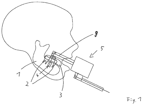
[0064] Figure 1 shows a human head with a jaw 1. Figure 1 includes two
depicted teeth
2. Furthermore, also shown is a hole 4, and laser beam 8 is directed upon the
base of the same. The laser is introduced using a handpiece 5. The handpiece 5
therein can be held by the physician or user, respectively. Being held means
merely that the weight of the handpiece is supported by the physician. The
precise alignment of the handpiece 5, or at least that of an end portion, is
determined by a dental splint 3 and the connecting means. Using laser beam 8,
the hole 4 is created by ablation from the jaw bone. A dental splint 3 is
applied to
these two teeth 2 and serves to fasten and/or align the handpiece 5.
[0065] A system of this kind can be used to create a hole 4 in a targeted
manner.
[0066] Figure 2 is a schematic representation of a system according to the
invention,
wherein the dental splint 3 is applied to a jaw 1 that is not part of the
system. The
observer recognizes a first connecting element 6, which is solidly and rigidly
connected to the dental splint 3. A second connecting means 7 is solidly and
rigidly connected to the end portion 14.The same, in turn, is solidly and
rigidly
connected to the scanner 11. Scanner 11, however, is movably connected to a
launch portion 16, which opens up into a laser 9. In this example, laser 9 is
disposed in a large movable housing launching the laser pulses thereof in the
launch portion 16, which is movable multiple times in itself and guides the
laser
beam. When the laser beam exits the launch portion 16 and enters the scanner
11, it can be deflected therein. The laser beam then enters an end portion 14,
19
CA 02804584 2013-01-07
where it is redirected in the direction of the jaw 1. The jaw material can be
ablated at that location.
[0067] Figure 3 is a cross-section of the system according to the invention.
Furthermore,
also shown is a jaw 1. A dental splint 3 is placed onto the jaw 1, which is
fastened at that location by means of a positive fit. The dental splint 3
includes a
first connecting means 6 that engages with a second connecting means 7. An
end portion 14 and a scanner 11 are fixedly connected to the second connecting
means 7. For the launch of a laser beam 8, scanner 11 has a light guide 10
into
which a pulsed laser, which is generated in a laser, is launched as laser beam
8
into scanner 11. Located inside scanner 11 are two scanner mirrors 12, which
are fastened each on a motion device 13. Said motion device 13 is computer-
controlled and allows for deflecting laser beam 8 in different directions and
planes. This is indicated by a plurality of laser beams 8 depicted in
different
shades of grey. Laser beams 8, which are deflected in this manner, are
incident
in end portion 14 upon a fixedly disposed deflecting mirror 15 and are thereby
redirected in the direction of the jaw 1. This is how they ablate jaw material
and
create hole 4.
[0068] Figure 4 shows the representation from Figure 3, but with a cooling
agent supply
channel 22, a cooling agent nozzle 23 and a suction channel 24. Channels 22,
24 include the corresponding hook-ups on the outside for connecting a supply
and/or suction means. The nozzle 23 directs the jet of cooling agent upon the
location where the ablation occurs. The flow direction of the cooling agent is
illustrated by the arrows.
CA 02804584 2013-01-07
[0069] Figure 5 shows the handpiece 5. The connecting means and the dental
splint
therein are not depicted. The laser beam 8 is launched via scanner 11 and the
scanner mirror 12 thereof as well as via deflecting mirror 15 into the hole 4.
There, the beam is partially reflected and subsequently redirected via a
triangulation mirror 20, which is disposed in an additionally mounted
triangulation
arm 18, to a CCD 19. By the displacement of the laser beam 8 on the CCD 19, it
is possible to detect the change relative to the depth of the hole 4.
Advantageously, a laser beam 8 is used therein, which does not result in an
ablation. By the movement of the scanner mirror 12, it is possible to move the
laser beam 8 inside hole 4. This way it is possible to detect the depth and/or
the
change in depth of the hole 4 at different locations. When the energy of the
laser
beam 8 is increased, which causes an ablation to occur, there results an
ablation
noise 21, which is indicated by wave fronts. Said ablation noise 21 hits the
microphones 17 and is detected by the same. This way, it is possible to gather
information as to the structure on which the ablation noise 21 has occurred.
Moreover, if the point in time is known, when laser beam 8 arrives in hole 4
and/or passes the handpiece 5 or is generated outside of the handpiece 5, it
is
possible to determine the depth of the hole 4 and/or the distance of the base
thereof relative to the microphones 17. Knowledge as to the exact time of when
the beam arrives at the base of the hole 4 is not required, because the
reflection
time of laser beam 8 is minimal in relation to the reflection time of the
acoustic
waves of the ablation noise 21 and can be neglected.
21
CA 02804584 2013-01-07
[0070] Figure 6 is a schematic representation of a second system according to
the
invention having a movable arm for guiding the laser beam 8. The arm in part
includes light guides 10. A scanner 11 is disposed inside the arm. The arm can
be rotated or bent at a plurality of locations. These degrees of freedom are
indicated by arrows. A handpiece 5 is disposed on and connected to the arm.
Dental splint 3 is also shown.
[0071] An embodiment with a movable arm is associated with numerous benefits
for the
practical application inside the oral cavity.
[0072] Figure 7 is a schematic representation of a third system according to
the
invention similarly to Figure 6, wherein a scanner 11 is disposed at the base
of
the arm.
[0073] Further advantageous embodied examples can be easily devised by the
person
skilled in the art and, if necessary, adapted to the respective requirements.
[0074] List of reference signs:
1. Jaw
2. Tooth
3. Dental splint
4. Hole
5. Handpiece
6. First connecting means
7. Second connecting means
8. Laser beam
9. Laser
22
CA 02804584 2013-01-07
10. Light guide
11. Scanner
12. Scanner mirror
13. Motion device
14. End portion
15. Deflecting mirror
16. Launch portion
17. Microphone
18. Triangulation arm
19. CCD
20. Triangulation mirror
21. Ablation noise
22. Cooling agent supply channel
23. Cooling agent nozzle
24. Suction channel
23