Note: Descriptions are shown in the official language in which they were submitted.
PLASTIC CONTAINER
FIELD
The improvements generally relate to the field of plastic containers, and more
particularly
to tamper-evidence and leak proof characteristics thereof.
BACKGROUND
It is well known to use plastic containers to sell many types of goods. For
instance, it is commonplace in the art that goods such as food or fasteners be
provided
in plastic containers. Such plastic containers can be made of various types of
plastics,
and can be made by thermoforming or injection, for instance.
For the purchaser of such goods to feel confident about the purchase, various
means to
prevent tampering with the goods have been presented in the past. Some of
these deal
with making the container more difficult to open, such as requiring a tool for
instance.
Another approach has been to design the container in a manner that opening it
requires
breakage of a component, thereby presenting evidence that the container had
been
tampered with. Although many different designs were presented in the past,
many of
which were satisfactory to a certain degree, there still remained room for
improvement.
Furthermore, for containing liquids, there remained room for improved
containers having
a satisfactory seal formed between the lid and the receptacle.
SUMMARY
In accordance with one aspect, there is provided a plastic container having a
lid and a
receptacle, the receptacle and the lid having corresponding engagement potions
matingly shaped for the lid and the receptacle to be maintained in a closed
configuration
by a resilient effect, the lid having a closure, a lid wall extending upwardly
from an outer
end of the closure and including an outwardly protruding rib, a rim parallel
to and
upwardly offset from the closure and extending outwardly from an upper end of
the lid
wall, and a handle lip extending vertically downwardly from a horizontal edge
of the lid,
the handle lip being shaped to allow overcoming the resilient effect when
manually
pulled upwardly; the receptacle having a detachable barrier strip covering the
handle lip
and preventing manual pulling access thereto; the receptacle having a
receptacle rim, a
receptacle wall portion extending downwardly from an inner side of the
receptacle rim,
an upwardly protruding receptacle rib providing abutment support to the lid
closure, and
a gutter surrounding the receptacle rib, wherein the receptacle wall portion
projects
upwardly from an outer side of the gutter, the receptacle wall portion having
an inwardly
- -
CA 2804720 2017-08-30
protruding portion shaped to resiliently trap the outwardly protruding rib of
the lid below
it, i.e. below the inwardly protruding portion, and an engagement portion
inclined so as to
face both inwardly and downwardly in a manner to further exert upon the
outwardly
protruding rib a sealing force which presses the lid closure against the
receptacle rib.
In accordance with another aspect, there is provided a plastic container
comprising : a lid
having a lid rim, a handle lip extending downwardly from an outer side of the
lid rim
and having a free lower end, a closure parallel to and downwardly offset from
the
lid rim, and a lid wall upwardly connecting a periphery of the closure to an
inner
side of the lid rim, the lid wall having an outwardly protruding rib; a
receptacle having
a receptacle rim, a receptacle wall portion extending downwardly from an inner
side of
the receptacle rim, an upwardly protruding receptacle rib providing abutment
support to
the lid closure, and a gutter surrounding the receptacle rib, the receptacle
wall portion
projecting upwardly from an outer side of the gutter and having an inwardly
protruding
portion shaped to resiliently trap the rib of the lid below it, i.e. below the
inwardly
protruding portion, and a tearable barrier strip detachably connected to the
receptacle
rim and being shaped as an elongated U to house the handle lip and prevent
manual
access to at least the free lower end thereof, and an engagement portion
inclined so as
to face both inwardly and downwardly in a manner to further exert upon the
outwardly
protruding rib a sealing force which presses the lid closure against the
receptacle rib;
whereby the lid is manually openable only after the barrier strip has been
teared away to
provide manual access to the handle lip.
In accordance with another aspect, there is provided a plastic container
comprising : a lid
having a lid rim, a closure parallel to and downwardly offset from the lid
rim, and a lid
wall upwardly connecting a periphery of the closure to an inner side of the
lid rim, the lid
wall having an outwardly protruding rib; and a receptacle having an upwardly
protruding
receptacle rib providing sealing abutment support to the lid closure, a gutter
surrounding the receptacle rib, and a receptacle wall portion projecting
upwardly from
an outer side of the gutter, the receptacle wall portion having an inwardly
protruding
engagement portion matingly shaped to resiliently receive the outwardly
protruding rib
of the lid below it, i.e. below the inwardly protruding engagement portion,
and inclined so
as to face both inwardly and downwardly in a manner to further exert upon the
outwardly
protruding rib a sealing force which presses the lid closure against the
receptacle rib.
-2 -
CA 2804720 2017-08-30
CA 02804720 2016-08-26
DESCRIPTION OF THE FIGURES
In the figures,
Fig. 1 is a perspective view of an embodiment of a plastic container;
Fig. 2A to 2D are successive views showing closing and opening of the plastic
container
of Fig. 1;
Fig. 3 is a cross-sectional view of the plastic container of Fig. 1; and
Fig. 4A to 4C are enlarged cross-sectional views corresponding to Figs 2A to
20,
respectively.
DETAILED DESCRIPTION
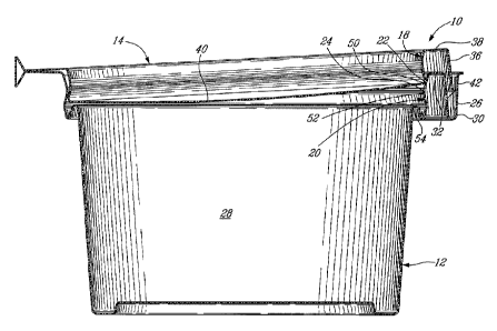
Fig. 1 shows an embodiment of a plastic container 10. The plastic container 10
can be
seen to be generally comprised of a receptacle 12 and a lid 14, both of which
are
made of a thin sheet of plastic. It will be understood by those skilled in the
art that an
embodiment such as shown or similar can be realised by thermoforming or
injection
moulding from a wide variety of plastics, for example. In this particular
embodiment,
the plastic container 10 is thermoformed and the lid 14 is connected to the
receptacle
by a hinge 16. Further, this particular embodiment is designed to be
stackable in either one of the closed and open configurations as can be
appreciated
from the illustration.
- 2a -
PCT/CA2011/050430
CA 02804720 2013-01-08
16 May 2012 16-05-2012
More particularly, still referring to the embodiment shown in Fig. 1, the
inner wall 18 of
the lid 14 and the upper internal portion 20 of the receptacle 12 are provided
with mating
engagement portions (22, 24 - Fig. 3) which are resiliently engaged with one
another
when the lid 14 is closed on the receptacle 12 and thereafter maintained in
engagement
by a resilient effect due to the shape of the plastic container and the
elasticity of the
material it is made of. This will be detailed further below with reference to
Figs. 4A to 4B.
The receptacle 12 has a barrier strip 26 which surrounds the entirety, or
quasi-entirety of
the cavity 28 to the exception of the hinge 16. The barrier strip 26 has a U-
shaped
channel 30, better seen on Fig. 3, and is independent from the engagement
portion 24 of
the receptacle 12 (i.e. it has no part in the resilient effect which maintains
the lid 14
engaged with the receptacle 12 once closed). The barrier strip 26 is
detachable from the
remainder of the receptacle 12 by tearing along a tear line 32, and one tab 34
or more
can be provided to help holding the barrier strip 26 when detaching it from
the remainder
of the receptacle 12. The lid 14, on the other hand, has a handle lip 36which
projects
substantially normally from the lid rim 38, in the same direction than the lid
closure 40
also projects from the lid rim 38.
Turning to Fig. 29, it can be appreciated that the plastic container 10 Is
configured in a
manner that the handle lip 36 is effectively nested in the U-shaped channel 30
of the
barrier strip 26 when the lid 14 is engaged with the receptacle 12. In this
configuration,
an average person cannot reach the free lower end of the handle lip 36 of the
lid 14 with
his/her fingers because the opening between the handle lip 36 and the outer
wall 42 of
the barrier strip 26 is too small. An average person therefore finds no grip
to open the lid
14. The lid 14 is thus prevented from being manually opened from the closed
position by
the combination of the resilient effect of the engagement (22, 24 - Fig. 3)
portions and
the barrier strip. To restore manual access to the handle lip 36, the barrier
strip 26 must
be at least partially detached (i.e. torn along the tear line 32 - Fig. 1),
which leaves
irreversible evidence of tampering.
Turning to Fig. 2C, once a consumer purchases the goods with the plastic
container 10,
the consumer can remove the barrier strip 26 In one easy step, thereby freeing
the
handle lip 36 from the barrier. The plastic container 10 can then be easily
manually
opened into the configuration shown in Fig. 2D by pulling the handle lip 36
upwardly. It
will be appreciated by those skilled in the art that the embodiment shown In
the attached
figures can thereafter be opened and closed more than once by the purchaser,
and
further offers a highly practical and easy grip due to the fact that the
handle lip 36
projects vertically downwardly and does so along a significant distance.
Furthermore,
there is a convenient finger spacing 44 provided behind the handle lip 36.
These latter
features are visible more clearly on Fig. 4C.
Turning now to Fig. 3, the details of the engagement portions 22, 24 which
serve to
cause the resilient effect which maintains the lid 14 closed against the
receptacle 14
independently of the
- 3 -
AMENDED SHEET
CA 02804720 2013-01-08
WO 2012/006739 PCT/CA2011/050430
eventual removal of the barrier strip 26 are shown in greater detail. In fact,
it will be seen in the
details of this particular embodiment that the closure 40 of the lid 14 is
parallel to the rim 38 of the
lid 14, but downwardly projects therefrom and is thus offset. The quasi-
annular lid wall 18 which
vertically interconnects the periphery of the lid closure 40 to the lid rim 38
is formed with a
correspondingly quasi-annularly shaped outwardly protruding bulge referred to
herein as an
annular or peripheral engagement rib 50. The lid closure 40 itself in this
embodiment is relatively
flat, but it nonetheless defines a slight camber oriented in the direction of
the cavity 28, the
purpose of which will be detailed below.
Looking now more particularly at the receptacle 12, and still referring to
Fig. 3, it can be
appreciated that the upper wall portion 20 of the receptacle also has a quasi-
annular bulge or
engagement rib 52, but which protrudes inwardly. The expression annular or
quasi annular are
used herein to refer to the fact that the given features surround the
container 10, independently of
whether the container 10 is circular or not. It will be understood that the
particular configuration of
which is to be designed given the elasticity of the material(s) used, in a
manner that the inwardly
protruding engagement rib 52 of the receptacle 12 normally interferes with the
shape and
dimension of the rib 50 in the lid, but that at least one of the two
components will resiliently yield to
allow the rib 50 in the lid 14 to penetrate into the area underneath the
inwardly protruding rib 52 of
the receptacle wall portion 20 in a somewhat snapping resilient effect. This
action can be seen
more clearly by referring successively to Fig. 4A and Fig. 4B.
As shown in Fig. 4B, once the lid 14 has been forced into the closed position,
the lid 14, and more
particularly the closure 40 thereof, comes into abutment with an upwardly-
oriented peripheral
abutment 54 provided as part of the receptacle 12. At this point, the rib 50
of the lid 14 is pressed
against an engagement portion 56 of the receptacle wall portion 20 which is
inclined so as to face
both inwardly and downwardly. The force F exerted between the engagement
portion 56 and the
lid rib 50 thus both maintains the lid rib 50 pressed against the engagement
portion 56, but the
vertical portion of the reaction to this force F also maintains the closure 40
pressed against the
abutment 54. In this particular configuration, the fact that the closure 40 is
cambered contributes
to this resilient effect and creation of the force F. Further, because the
closure is cambered toward
the cavity 28, a pressure increase occurring in the cavity upon closing the
lid will act against the
closure 40, tend to press upwardly against the camber and thus further push
the annular lid rib 50
against the engagement portion 56 of the receptacle 12, and thereby strengthen
the lock and seal.
A pressure increase typically occurs for instance as the lid is pushed closed
against the
receptacle, but can also occur in other circumstances, such as if liquid is
shaken in the container,
for instance. It will be noted here that in this particular embodiment, a
gutter shaped member, or
gutter 58, is provided between the peripheral abutment 54 and the engagement
portion 56. It will
be noted that the gutter is free from interference with the lid 14, and that
it can contribute to the
resilient effect by acting in the manner of a spring biasing the engagement
portion 56 inwardly. A
- 4 -
CA 02804720 2013-01-08
WO 2012/006739 PCT/CA2011/050430
form of spring can thus be said to be formed in the receptacle portion 12 by
the "S" shape formed
by the combination of the peripheral abutment 54 and the gutter 58, given the
elasticity of the
plastic material, and a form of spring is formed in the lid portion with the
camber in the closure 40,
the two springs working together to lock the lid in the closed position and
form an effective seal.
In certain applications where fluid matter is to be contained in the container
10, it is desirable that
an effective seal be provided between lid 14 and the receptacle 12 to prevent
or at least limit the
evacuation of fluid between the lid 14 and receptacle 12. Positioning a rib
made of the resilient
plastic material in a manner that it be maintained in pressing contact with a
flatter surface can
allow to achieve a satisfactory seal in certain applications. In the
particular configuration
illustrated, the plastic container is designed with two distinct features
where this occurs firstly
where the peripheral abutment 54 forming a rib is maintained pressed against
the flatter surface of
the closure 40, and secondly, where the lid rib 50 is maintained pressed
against the engagement
portion 56 of the receptacle 12. Both of these features can thus be designed
to form an
independent seal along the entire periphery of the container. The presence of
two distinct seals,
separated here by the gutter 58 for instance, can increase the sealing
efficiency. Further, the
efficiency of the seal can also be affected by the radius of the rib. The
peripheral abutment 54 of
the receptacle 12 can thus be referred to as the sealing rib of the receptacle
12, whereas the
peripheral rib 50 of the lid 14 acts as a sealing rib of the lid 14. It will
be understood that the
presence of a gutter 58 is optional, and that if used, it can be oriented
otherwise than downwardly
in alternate embodiments, such as laterally for instance.
It will be understood that the embodiment described herein and illustrated are
provided for
illustrative purposes only and that the improvements can be embodied in a wide
variety of
alternate embodiments or realizations. For instance, alternate embodiments can
include plastic
containers made with injection moulding, plastic containers having
distinct/unconnected lid and
receptacle, plastic containers not intended to be leak-resistant, or plastic
containers without
tamper-evident features. Where present, the hinge can alternately consist of a
simple fold, for
instance. Although the depicted container has an oval horizontal cross-
section, it can have other
closed curved shape, ranging from closer to a circle, to closer to a rectangle
but without sharp
corners, for instance. The wall portion, rims, ribs, handle lip and barrier
strip can be shaped to
correspond with the alternate shape of the horizontal cross-section. Further,
it is to be understood
that the expressions up and down, vertical and horizontal, etc. are used
herein for convenience
and typically refer to the container when it is laid flat on a horizontal
surface. The expressions
inwardly/outwardly refer to the inside of the container, and often refer to a
horizontal or vertical
orientation relative to the inside of the container. The expression vertical
in particular must be
interpreted with some breadth as encompassing features which are close to
vertical. The
expression oval can be interpreted rather loosely and can include an ellipse.
It will also be
understood that reference is often made to the container in its closed
configuration to discuss
- 5 -
CA 02804720 2013-01-08
WO 2012/006739
PCT/CA2011/050430
sealing, engaging, and tamper-evident features, for instance. This thorough
description provided
for the convenience of the skilled reader is thus not intended to be
interpreted in an unduly
restrictive manner.
As can be seen therefore, the examples described above and illustrated are
intended to be
exemplary only. The scope is indicated by the appended claims.
- 6 -