Note: Descriptions are shown in the official language in which they were submitted.
CA 02804748 2014-09-22
= ,
Protective foot for a unit load, in particular concrete tower segments
The present invention concerns a protective foot for a unit load or
piece goods item, in particular concrete pylon segments.
Conventionally an item of piece goods such as for example a pylon
section segment or a (concrete) pylon segment is protected from damage
by the surface beneath it by wood blocks which are placed beneath it. To
avoid horizontal movement a rubber mat can be placed between the item
and the wood block and between the wood block and the underneath
surface. As an alternative thereto for example upon transport on a freight
ship it is also possible to weld steel feet and/or stopper plates on the
transport surface, which are intended to prevent the item from moving
horizontally.
When using wood blocks and rubber mats there is the risk of slipping
during transport, whereby an item no longer enjoys adequate protection.
The use of steel feet for avoiding horizontal movement involves the risk of
damaging the item of piece goods. Continuously working with wood blocks
and rubber mats entails a considerable level of complication and
expenditure.
Upon unloading they first remain lying around and
subsequently have to be collected up for further use while the piece goods
item after unloading has to be protected by fresh wood blocks and rubber
mats. It can also happen that they can no longer be found due to negligent
handling (they are forgotten or thrown away) and thus cannot be re-used.
On top of everything, that kind of safeguarding piece goods is linked to
dangers to the person implementing such procedures.
As general state of the art attention is directed to DD 154 785 A3.
The object of the present invention is to provide a protective foot for
a piece goods item, in particular a pylon section segment, for use during
transport and storage.
That object is attained by a protective foot as described below.
CA 02804748 2013-01-08
2
The protective foot has a (substantially horizontal) portion of
predetermined length (hereinafter referred to as the bottom plate) and at
least one fixing portion for releasably fitting the foot to the piece goods
item.
The invention concerns the notion of providing a protective foot
which is connected permanently but releasably to the piece goods item.
That considerably reduces the complication and expenditure for
safeguarding the item during transport and intermediate storage. The
working steps which are usually involved in loading operations for
protecting a piece goods item can be omitted for the major part, which
saves on time and thus cost. Equally the danger to the transport personnel
is considerably reduced by virtue of elimination of the securing steps during
transport.
If such a foot can additionally be easily arrested and demounted
(dismantled), it can be employed again for further uses, thereby saving
resources and reducing cost. That is additionally promoted by the foot
being of a compact configuration as return transport or further transport is
not made unnecessarily more difficult.
Reusability is further promoted by employing polyurethane as the
production material. In that way the foot can be repaired by filling. That
means that a damaged foot is not disposed of but is repaired and put to
further use.
Protection for the piece goods item from horizontal damage in the
transport procedure is achieved by fitting side portions to the bottom plate.
In addition side portions projecting perpendicularly from the bottom plate
can serve as a contact surface for stopper plates for safeguarding a load
against horizontal movement.
A drainage channel makes it possible to carry away water which has
penetrated into the foot, which could otherwise collect and could cause
damage due to deformation for example in the event of frost.
To protect a piece goods item from slipping on the transport surface,
a rubber coating or an anti-slip unit (anti-slip mat) can be glued into the
underside of the foot. As a further improvement and to provide protection
CA 02804748 2013-01-08
3
from slipping both of the item on the foot and also of the entire load on the
transport surface, the entire foot can be provided with a rubber coating.
That is important insofar as the foot cannot carry shearing forces which
occur upon horizontal movement of a heavy item. Experience has shown
that rubber-coating provides for a sufficient braking effect. Permanent
rubber-coating makes it unnecessary to place separate rubber mats
beneath the foot.
Further configurations of the invention are subject-matter of the
appendant claims.
Advantages and embodiments by way of example of the invention
are described in greater detail hereinafter with reference to the drawings.
Figure 1 shows a diagrammatic sectional view of a protective foot
according to a first embodiment,
Figure 2 shows a diagrammatic sectional view of a protective foot
according to a second embodiment,
Figure 3 shows a diagrammatic sectional view of a protective foot
according to a third embodiment,
Figure 4 shows a diagrammatic sectional view of a protective foot
according to a fourth embodiment,
Figure 5 shows a diagrammatic view of a protective foot according to
a fifth embodiment,
Figure 6 shows a diagrammatic sectional view of a protective foot
according to a sixth embodiment,
Figure 7 shows a diagrammatic sectional view of a protective foot
according to a seventh embodiment,
Figure 8 shows a diagrammatic sectional view of a protective foot
according to a eighth embodiment, and
Figure 9 shows a diagrammatic view of a protective foot according to
a ninth embodiment.
Figure 1 shows a sectional view of a protective foot in accordance
with a first embodiment. The protective foot has a bottom plate 1 and side
portions 7. For a piece goods item 100 such as for example a pylon section
segment of a wind power installation, the foot 10 as shown in Figure 1 can
CA 02804748 2014-09-22
. .
4
be fixed to the item or to the first end 110 thereof. That can be effected by
inwardly inclined side portions 7 which are connected to the bottom plate 1
and which are stressed outwardly when the foot is fitted on in place and
which press laterally against the item 100 after being released. The foot
can be easily removed again by again stressing the side portions 7
outwardly.
Optionally a first anti-slip unit (anti-slip mat) can be provided on
the underside of the bottom plate 1. In addition optionally a second
anti-slip unit (anti-slip mat) can be provided on a top side of the bottom
plate 1.
Figure 2 shows a diagrammatic sectional view of a protective foot
according to a second embodiment. The second embodiment represents an
alternative to the first embodiment. The protective foot 10 has a bottom
plate 1 and side portions 7. In this case the side portions 7 are not inclined
but project at a right angle from the bottom plate 1. Side portions 7
shaped in that way can serve at the same time for receiving stopper plates
to safeguard against horizontal movements, for example on freight ships.
Optionally a first anti-slip unit (anti-slip mat) can be provided on
the underside of the bottom plate 1. In addition optionally a second
anti-slip unit (anti-slip mat) can be provided on a top side of the bottom
plate 1.
Figure 3 shows a diagrammatic sectional view of a protective foot in
accordance with a third embodiment. The protective foot 10 has a bottom
plate 1 and side portions 8. In this case the side portions 8 are not
prestressed as in the first and second embodiments. Provided on the side
portions 8 are movable jaws 5 which can be respectively pressed against
the item 100 or against the first end 110 thereof in accordance with the
principle of a vise by means of an adjusting screw 6. The protective foot 1
can be released from the item 100 by simply releasing the jaws 5.
Optionally a first anti-slip unit (anti-slip mat) can be provided on
the underside of the bottom plate 1. In addition optionally a second
anti-slip unit (anti-slip mat) can be provided on a top side of the bottom
plate 1.
CA 02804748 2014-09-22
Figure 4 shows a diagrammatic sectional view of a protective foot
according to a fourth embodiment. In this case the protective foot 10 has a
bottom plate 1 and first and second side portions 4, 8. The first and
second side portions 4, 8 are preferably not provided in a prestressed
5 condition (as in the first and second embodiments). Provided on the first
side portion can be movable jaws 5 which can be pressed against the item
100 on the basis of the principle of a vise by means of an adjusting screw
6. The second side portion 4 preferably does not have a stressing device
so that the protective foot is fixed to a lower end of the item 100 by means
of the jaws 5 and the adjusting screw 6. The side portions can serve to
receive stopper plates and to provide a safeguard against horizontal
movement.
Optionally a first anti-slip unit (anti-slip mat) can be provided on
the underside of the bottom plate 1. In addition optionally a second
anti-slip unit (anti-slip mat) can be provided on a top side of the bottom
plate 1.
Figure 5 shows a diagrammatic view of a protective foot 10 according
to a fifth embodiment. In this case the protective foot 10 has a bottom
plate 1 and a fixing unit 2, 3 for fixing the protective foot 10 to the piece
goods item 100. The fixing unit has a spreading unit 2 and a screw 3 which
can be used on the basis of the principle of a dowel pin, that is to say when
the screw 3 is screwed into the spreading unit 2 the spreading unit 2 will
increase in width so that the fixing unit can be fixed in a hole in the item
100. Therefore the protective foot can be fixed to the item 100 by
tightening the screw 3. The fifth embodiment is particularly advantageous
in relation to piece goods items 100, the side surfaces of which do not
extend at a right angle from the base surface.
Optionally a first anti-slip unit (anti-slip mat) can be provided on
the underside of the bottom plate 1. In addition optionally a second
anti-slip unit (anti-slip mat) can be provided on a top side of the bottom
plate 1.
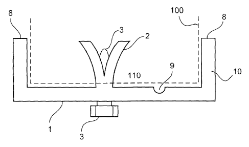
Figure 6 shows a diagrammatic sectional view of a protective foot
according to a sixth embodiment. The protective foot 10 has a bottom
CA 02804748 2014-09-22
6
plate 1 and side walls 8. The protective foot 10 further has a fixing unit 2,
3 and optionally a drainage channel 9. The fixing unit of the sixth
embodiment corresponds in this respect to the fixing unit of the fifth
embodiment. The drainage channel 9 can be provided at the top side of
the bottom plate 1 and serves for the protective foot. Water which is in the
protective foot can flow away through the drainage channel 9. That can
prevent water or moisture accumulating and being able to expand when
frost occurs and leading to damage to the item 100.
Optionally a first anti-slip unit (anti-slip mat) can be provided on
the underside of the bottom plate 1. In addition optionally a second
anti-slip unit (anti-slip mat) can be provided on a top side of the bottom
plate 1.
Figure 7 shows a diagrammatic sectional view of a protective foot
according to seventh embodiment. In the case the protective foot 10 has a
bottom plate 1 and a side wall 8 and a fixing unit 2, 3. In this case the
fixing unit in the seventh embodiment substantially corresponds to the
fixing unit of the fifth or sixth embodiment. In this case the fixing unit is
provided in the bottom plate 1.
Figure 8 shows a diagrammatic sectional view of a protective foot
according to the eighth embodiment. In this case the protective foot 10
has a bottom plate 1 and a side portion 8. In this case a fixing unit 2, 3
can be provided in the side portion 8. The fixing unit of the eighth
embodiment can in this case correspond to the fixing unit of the fifth, sixth
or seventh embodiment.
To provide lateral protection for piece goods items, the foot of Figure
6 can have side walls 8 which at the same time can serve to receive
stopper plates, as are used in ship transport situations. Figure 6 also
shows a drainage channel 9 which provides that no moisture accumulates,
which for example can cause considerable damage to the item by
expansion in the event of frost.
The pylon section segment can be in the form of a precast concrete
pylon portion or concrete pylon segment, in particular for a pylon of a wind
power installation.
CA 02804748 2014-09-22
f
7
In a further embodiment of the invention the bottom plate 1 and/or
the side portions 8 are of a thickness of about 4 - 5 cm.
Optionally a first anti-slip unit (anti-slip mat) can be provided on
the underside of the bottom plate 1. In addition optionally a second
anti-slip unit (anti-slip mat) can be provided on a top side of the bottom
plate 1.
Figure 9 shows a diagrammatic view of a piece goods item 100 and a
protective foot 10 according to a ninth embodiment. The protective foot 10
of the ninth embodiment can be based on one of the preceding
embodiments or a combination of the preceding embodiments.
In a further embodiment of the invention the fixing units (spreading
unit) can be fixed in holes at the end of the pylon section. That can provide
for easy handling upon fitting and removal both in a factory and also at the
building site. A first end of a piece goods item or a concrete pylon segment
or a pylon section segment or a pylon section can be protected from
chipping off when being set down or being transported, by the bottom plate
1.
Optionally a first anti-slip unit (anti-slip mat) can be provided on
the underside of the bottom plate 1. In addition optionally a second
anti-slip unit (anti-slip mat) can be provided on a top side of the bottom
plate 1.