Note: Descriptions are shown in the official language in which they were submitted.
CA 02804897 2013-01-09
PCT/CN2010/073927
Reinforcing Structure and Construction Method for Greening Vegetation
Articles
Field of the Invention
The present invention relates to a structure for reinforcing a greening member
and a
construction method thereof, which is suitable for the greening of the desert,
a soil slope,
and so on.
Background of the Invention
3.0 With the
increasing public attention to the ecological environment issues, the
greening of areas such as the desert, a slope and a river bank receive more
and more social
attention. The greening may be implemented in various manners, such as by
means of a net,
by means of placing fabrics, and by means of the stack of vegetation bags. The
greening
members used in these manners, such as the net, the fabrics and the vegetation
bag, are
mostly fastened on the surface of an afforesting area (i.e. an area to be
afforested) through
anchoring rods, which, if inserted into soil or deserts, may be loosened after
a period of
time due to the decreased friction force between the anchoring rod and the
soil or deserts,
and may be even drawn out, as a result, the greening members would be
displaced due to
such loosening, leading to a failure of the greening. Therefore, the fastening
manner by
means of the anchoring rod is unreliable and is not optimal for the greening.
Summary of the Invention
In view of the drawbacks in the prior art mentioned about, an object of the
present
invention is to provide a structure for reinforcing a greening member and a
construction
method thereof, which are advantageous for an improved effect of fastening.
To achieve the above object, the following technical solutions of the present
invention are provided.
A structure for reinforcing a greening member includes: a greening member
adapted
for being placed on a surface of an afforesting area; a positioning cover
adapted for
pressing on the greening member; a positioning member provided with a pivot
portion,
which is adapted for being inserted into the ground of the afforesting area;
and a rope, one
end of which is fastened to the pivot portion, and the other end of which is
extended out
from the ground of the afforesting area and extended through the greening
member to the
positioning cover, where the other end of the rope is fixed by the positioning
cover, so that
1
CA 02804897 2013-01-09
PCT/CN2010/073927
the rope is tensioned between the positioning cover and the positioning
member, with the
positioning cover pressing on the greening member.
The positioning cover may include a cover body and a locking sleeve, the cover
body
is provided with a through hole, the locking sleeve rests against a periphery
of the through
hole of the cover body, and the rope is extended through the hole and locked
by the locking
sleeve.
The positioning member may include a positioning body which is provided with a
longitudinal aperture, and the pivot portion is arranged on the periphery
(i.e. an outer
surface) of the positioning body.
A longitudinal ridge is extended from the periphery of the positioning body,
and the
longitudinal ridge is provided with a through hole, which functions as the
pivot portion and
to which one end of the rope is fastened.
A pair of lateral wings are symmetrically provided at both lateral sides of
the
positioning body.
A platform is provided at the periphery of the positioning body, and a cone-
shaped
stopper is longitudinally provided on the platform upwards.
A reinforcing layer adhering to the positioning member is provided between the
positioning member and the surface of the afforesting area.
The greening member is an ecological fabric, an ecological bag, a planting
bag, or a
greening grid; the positioning member is made of metal or plastic; and the
rope is a steel
wire, an iron wire or a plastic rope.
A method for constructing the structure for reinforcing a greening member
includes
steps of:
(1) fastening one end of the rope to the pivot portion of the positioning
member;
(2) inserting the positioning member into the ground of the afforesting area
by a
predetermined depth through a tool, with the rope being partially extended to
the ground of
the afforesting area along with the positioning member, and a portion of the
rope being
extended out from the ground of the area;
(3) pulling the rope outwards so that the positioning member is rotated about
the
pivot portion in the ground of the area by an angle;
(4) placing the greening member on the surface of the afforesting area; and
(5) passing the portion of the rope extended out from the ground of the area
through
the greening member and fastening the portion of the rope to the positioning
cover, so that
the rope is tensioned between the positioning cover and the positioning
member, with the
2
CA 02804897 2013-01-09
= PCT/CN2010/073927
positioning cover pressing on the greening member, allowing the greening
member to be
fixed on the surface of the afforesting area.
Further, a hollow pipe for injecting adhesive is attached to the tool, and one
end of
the hollow pipe is stuffed by a preset stopper on the positioning member. when
the
positioning member is inserted into the ground of the afforesting area by a
tool, the hollow
pipe is partially extended into the ground of the afforesting area along with
the tool, and
then the tool is drawn back by a distance so that the hollow pipe is separated
from the
stopper of the positioning member; then the rope is drawn outwards, and in the
process of
rotating the positioning member or when the rotating of the positioning member
is stopped,
adhesive is injected into the hollow pipe and penetrates the ground of the
afforesting area,
so that the positioning member is further fastened to the afforesting area.
The present invention is advantageous as follow. The positioning member
inserted
into the ground of the afforesting area may be rotated to be more firmly fixed
by the
increased resistance that is applied by the ground of the afforesting area to
the positioning
member, and the positioning cover is further fastened by the rope so that the
positioning
cover presses tightly on the greening member. In this case, the positioning
member inserted
into the ground of the afforesting area can be fully fixed without being
loosened, thus the
greening member can be firmly located on the ground of the afforesting area,
thereby
achieving an improved effect of fastening. Thus, the shortcoming of fastening
the greening
members by means of the anchoring rod in the prior art can be overcome, for
the purpose
of market promotion.
Brief Description of Drawings
Figure 1 schematically shows a first embodiment of the invention, which may be
applicable to a soil area to be afforested, in a state where the positioning
member is inserted
into the ground of the area for fastening a greening member such as a net or
an ecological
fabric;
Figure 2 schematically shows a state where the positioning member of Figure 1
has
been rotated and the greening member is fastened by the positioning cover;
Figure 3 schematically shows an exploded view of the positioning member, the
rope
and the positioning cover of the invention;
Figure 4 schematically shows a second embodiment of the invention, which may
be
applicable to a soil area to be afforested, in a state where the positioning
member is inserted
into the ground of the area for fastening a greening member such as an
vegetation bag;
Figure 5 schematically shows a state where the positioning member of Figure 4
has
3
= CA 02804897 2013-01-09
= PCT/CN2010/073927
been rotated;
Figure 6 schematically shows a third embodiment of the invention, which may be
applicable to a sand or soil area to be afforested, in a state where the
positioning member is
inserted into the ground of the area for fastening a greening member such as
an ecological
fabric;
Figure 7 schematically shows a state where the positioning member of Figure 6
has
been rotated and the greening member is fastened by the positioning cover; and
Figure 8 schematically shows an exploded view of the positioning member, the
rope
and the positioning cover of the third embodiment of the invention.
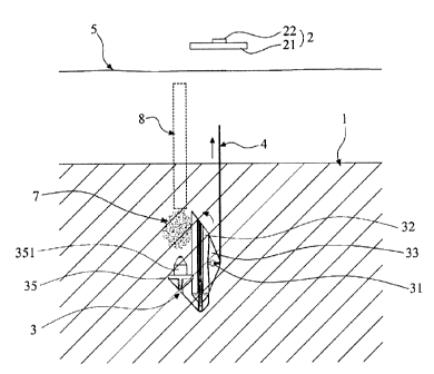
3.0 Reference numeral list
1: Afforesting area 2: Positioning cover
21: Cover body 22: Locking sleeve
3: Positioning member 31: Pivot portion
32: Positioning body 321: Longitudinal aperture
33: Longitudinal ridge 34: Lateral wing
35: Platform 351: Stopper
4: Rope 5: Net or ecological fabric
6: Greening material 7: Reinforcing layer
8: Hollow pipe
Detailed Description of Preferred Embodiments
The present invention is described below with reference to the attached
drawings and
embodiments.
With reference to Figures 1-3, a reinforcing structure for fastening a net or
an
ecological fabric (i.e. a greening member), that may be applicable to a soil
area 1 to be
afforested, is shown. The reinforcing structure includes: a greening net or
ecological fabric
5 for being placed on a surface of the area 1 to be afforested, and the
greening net or
ecological fabric 5 may be placed after greening materials 6 (e. g. plant
growing materials,
water absorbent materials) are placed on the surface of the area 1 for the
purpose of
planting, or the greening materials 6 may be placed on the greening net or
ecological fabric
5 for the purpose of planting; a positioning cover 2 adapted pressing on the
greening net or
ecological fabric 5 to prevent displacement thereof; a positioning member 3
provided with
4
CA 02804897 2014-05-02
a pivot portion 31, which is adapted for being inserted into the ground of the
area 1 to be
afforested; a rope 4, one end of which is fastened to the pivot portion 31,
and the other end
of which is extended out from the ground of the area 1 and extended through
the greening
net or ecological fabric 5 to the positioning cover 2, where the other end of
the rope 4 is
fixed by the positioning cover 2, so that the rope 4 is tensioned between the
positioning
cover 2 and the positioning member 3, with the positioning cover 2 pressing on
the
greening net or ecological fabric 5, here the rope 4 may be made from steel,
iron or plastic.
The positioning cover 2 may include a cover body 21 and a locking sleeve 22,
the
cover body may be provided with a through hole 211, the locking sleeve 22 may
be made
of metal and rest against the periphery of the through hole 211, and the rope
4 is extended
through the through hole 211 and into the locking sleeve 22, and then locked
by the locking
sleeve 22 that is deformed.
The positioning member 3 may be of a column-like shape and made of metal or
plastic. The positioning member 3 may include a positioning body 32 which is
provided
with a longitudinal aperture 321, into which a tool may be inserted to press
the positioning
member 3 into the ground of the area 1 to be afforested. The pivot portion 31
is arranged on
the periphery of the positioning body 32, that is, a longitudinal ridge 33 is
extended from
the periphery of the positioning body 32, and the longitudinal ridge 33 is
provided with a
through hole, which functions as the pivot portion 31 and to which one end of
the rope 4 is
fastened. A pair of lateral wings 34, which are relatively narrow, are
symmetrically
provided at both lateral sides of the positioning body 32, so that the
positioning member 3
will be subjected to effectively increased resistance after being rotated in
the area 1 to be
afforested. A reinforcing layer 7 adhering to the positioning member 3 is
provided between
the positioning member 3 and the surface of the area 1 for afforesting. The
reinforcing layer
7 may be formed of adhesive or cement. For the sake of injecting the adhesive
or cement, a
platform 35 may be provided at the periphery of the positioning body 32 of the
positioning
member 3, and a cone-shaped stopper 351 is longitudinally provided on the
platform 35
upwards, to plug the hollow pipe 8 for injecting the adhesive or cement, so
that earth will
not enter into the hollow pipe 8 when the positioning member 3 is being
inserted into the
ground.
In use, one end of the rope 4 is fastened to the pivot portion 31 of the
positioning
member 3, then the positioning member 3 is inserted forcedly into the ground
of the area 1
for greening to a predetermined depth through a tool such as a vibrator. At
this time, a
portion of the rope 4 is extended into the ground of the area 1 along with the
positioning
member 3, but a portion of the rope 4 is still exposed above the ground. Then,
the rope 4 is
drawn outwards (e. g. by means of a certain tool) to cause the positioning
member 3 to
rotate about the pivot portion 31 by a certain degree under the ground of the
area 1,
5
CA 02804897 2013-01-09
PCT/CN2010/073927
Then, the greening net or ecological fabric 5 is placed on the surface of the
area 1 for
afforesting, the portion of the rope 4 that is exposed above the ground of the
area 1 for
afforesting is extended through the greening net or ecological fabric 5, then
the positioning
cover 2 is pressed on the greening net or ecological fabric 5, and the exposed
portion of the
rope 4 is extended through and fixed to the positioning cover 2, so that the
rope 4 is tightly
tensioned between the positioning cover 2 and the positioning member 3. Thus,
the
positioning cover 4 is tightly pressed against the greening net or ecological
fabric 5, which
may be hence fixed stably on the surface of the area 1 for afforesting. For
the purpose of
injecting the adhesive or cement to form the reinforcing layer 7, the hollow
pipe 8 for
injecting the adhesive or cement is connected to the tool such as a vibrator,
and one end of
the hollow pipe 8 is blocked by the stopper 351. When the positioning member 3
is inserted
into the ground of the area 1 by a certain tool, a portion of the pipe 8 is
also extended into
the ground along with the tool. Subsequently, the tool as well as the hollow
pipe 8 is drawn
back by a certain distance so that the pipe 8 is separated from the stopper
351 of the
positioning member 3 by a certain gap, and then the adhesive or cement is
injected through
the pipe 8 and penetrates the ground of the area for afforesting. Further, the
rope 4 is drawn
outwards. After the adhesive is solidified, a reinforcing layer 7 is formed
between the
positioning member 3 and the area 1 for afforesting, to achieve a better
effect of fastening.
Alternatively, the adhesive may be injected through the pipe 8 during or after
the rotation
of the positioning member 3.
Figures 4-5 show a second embodiment of the present invention applicable to a
soil
area 1 for afforesting. The second embodiment is different from the first
embodiment in
that the greening member is a vegetation bag 5 other than the greening net or
fabric. The
vegetation bag may be filled with plant growing materials for planting. The
other parts
including the positioning cover 2, the positioning member 3, the pivot portion
31, the rope
4, and so on and the construction method thereof are the same as in the first
embodiment,
and detailed description is omitted.
The embodiment shown in Figures 6-8 may be applicable to a sand area 1 for
afforesting (e. g. a desert), to fasten greening members such as an ecological
fabric or a
greening net 5. Considering that the sand area is relatively soft, the pair of
lateral wings 34
symmetrically provided at both lateral sides of the positioning body 32 are
shaped as thin
plates with a large area, for the ease of rotating in the sand area. In this
case, one end of the
rope 4 is fastened to the pivot portion 31 of the positioning member 3, then
the positioning
member 3 is inserted forcedly into the ground of the area 1 for afforesting,
and then the
rope 4 is drawn upwards to cause the positioning member 3 to rotate
horizontally, until the
lateral wings 34 are arranged horizontally. As a result, the area of the
entire plate-shaped
lateral wings 34 serves as the resistance area, and the resistance applied to
the positioning
member 3 under the ground of the area 1 is effectively increased. The other
aspects of the
6
CA 02804897 2014-05-02
present embodiment, such as the positioning cover 2 including the cover body 2
and the
locking sleeve 22, the positioning member 3 including a positioning body 32 in
which a
longitudinal aperture 321 is provided, the platform 35 and the cone-shaped
stopper 351 on
the platform that are arranged at the side of the positioning member 3, and
the method of
injecting the adhesive through the hollow pipe to form the reinforcing layer
7, are the same
as those of the previous embodiments. It will be appreciated that the
ecological fabric or
greening net 5 may be replaced by vegetation bags.
As can be seen from the above embodiment, different positioning members may be
selected depending on the types of the areas for afforesting. The positioning
member may
be pressed forcedly into the ground of the afforesting area, and then caused
to rotate under
the ground by the pulling of the rope, so that the positioning member would be
subjected to
an increased resistance in the ground of the afforesting area, thus the
positioning member is
not easy to be pulled out from the ground. Further, the rope is fastened to
the positioning
cover, to cause the positioning cover to firmly press the greening member. The
positioning
member which is firmly held under the ground of the afforesting area will not
be loosened,
thus the greening member can be firmly located on the surface of the
afforesting area, to
overcome the drawback of the traditional anchor rod.
While reference has been made to various preferred embodiments of the
invention
other variations, implementations, modifications, alterations and embodiments
are
comprehended by the broad scope of the appended claims. Some of these have
been
discussed in detail in this specification and others will be apparent to those
skilled in the art.
Those of ordinary skill in the art having access to the teachings herein will
recognize these
additional variations, implementations, modifications, alterations and
embodiments, all of
which are within the scope of the present invention, which invention is
limited only by the
appended claims.
7