Note: Descriptions are shown in the official language in which they were submitted.
WO 2012/010878 CA 02804959 2013-01-10PCT/GB2011/051350
1
INHALER
Technical field
The present invention relates to an inhaler having a mouthpiece (or nosepiece)
and
a cover which is movable so as either to enclose the mouthpiece to protect it
when the
inhaler is stored, or to or expose the mouthpiece for use.
Background of the Invention
There are different types of inhalers on the market. A pressurized metered
dose
inhaler (pMDI) releases a fixed dose of substance in aerosol form. A powder
inhaler
generally releases a dose of powdered substance entrained in an air stream. In
a powder
inhaler the powder may be provided in a bulk container of the inhaler from
which doses of
powder are metered for dispensing. As an alternative to a bulk container,
powder inhalers
may comprise a single compartment or a plurality of compartments for
containing one or
more discrete doses of powdered substance. Such compartments may take the form
of
sealed blisters in a blister pack, a flexible strip of sealed cavities or
other suitable forms.
Whatever the type of inhaler, an air inlet is normally required through which
air is
drawn into and then through the inhaler when the user inhales through the
mouthpiece (or
nose piece in some cases). In a dry powder inhaler, the air flow path is
carefully designed
so that the air passing through the inhaler entrains and deaggregates dry
powder
medicament, but pressurised metered dose inhalers also need to allow a flow of
air to be
taken into the lungs of a user at the same time as the medicament, and this
would normally
be drawn through the inhaler and then out of the mouthpiece together with the
medicament.
A problem can arise if the user inadvertently covers the inlet with his or her
hand
while using the inhaler. The flow of air to the user may be reduced and this
may affect the
delivered dose of medicament without it being obvious to the user that
anything is amiss.
It is therefore desirable for the air inlet in an inhaler to be positioned in
such a way that
makes it difficult for a user to obstruct it when using the inhaler.
It is desirable for the air inlet as well as the mouthpiece to be covered when
the
inhaler is not in use to avoid contamination of the airway with foreign
substances (e.g. dust
WO 2012/010878 CA 02804959 2013-01-
102 PCT/GB2011/051350
from a pocket in which the inhaler is carried). Inadvertent inhalation of such
substances is
to be avoided.
It is desirable for an inhaler to have a mouthpiece which has sufficient
length to
allow the user to make a good seal around it with their mouth. The inhaler is
preferably
also aesthetically pleasing for the user, which can sometimes be at odds with
the objective
of having a long mouthpiece.
It is desirable to avoid creating additional air flow paths from the
atmosphere into a
main flow path from the air inlet to the mouthpiece. One or more bypass air
flow channels
may be provided whose flow characteristics are carefully defined and whose
contribution
ici to the overall pressure drop and flow rate when the inhaler is used
is carefully factored in.
However, so-called leakage flow through e.g. ill-fitting components, apertures
created as
part of a moulding process, windows in the inhaler casing for displaying a
dose count, etc,
is desirably to be avoided.
One design of dry powder inhaler is disclosed in US5590645 (Glaxo). This dry
is powder inhaler has the general form of a disc, with the mouthpiece
provided at the edge of
the disc. A cover is pivoted to the central axis of the disc; the cover being
generally flush
with the overall profile of the device to make for a device with a generally
pleasing overall
appearance. The air inlet is located in one of the major faces of the disc;
this is clearly the
case in the product corresponding to this patent, known as Diskus0 (trade mark
of
20 GlaxoSmithKline plc). In US5590645 Figures 13-16 show the closest
embodiment to the
marketed product, though the location of the air inlet(s) is not clear;
however, the location
of the inlet can be deduced from the air flow diagram in Figures 4a and 11. It
may be
possible for a user to block or partially block this inlet when holding the
inhaler in order to
use it. The mouthpiece in this inhaler (referring the commercial product and
to Figures 13-
25 16) is both relatively short and also recessed with respect to the
edge profile of the inhaler;
this allows the cover to be substantially flush with the overall profile of
the device.
Summary of the Invention
An object of the present invention is to avoid drawbacks associated with some
prior
30 inhalers. This and other objects, which will become apparent in the
following, are
accomplished by the inhaler and the methods defined in the accompanying
claims.
WO 2012/010878 CA 02804959 2013-01-103
PCT/GB2011/051350
An inhaler comprises:
- a housing including a mouthpiece;
- a cover movably mounted to the housing so as to be movable between an
open
configuration of the inhaler in which the mouthpiece is exposed for use and a
closed configuration of the inhaler in which the mouthpiece is enclosed;
- wherein, in the open position, the cover at least partly defines an
inlet aperture
to an inhalation air flow path leading through the inhaler and communicating
with
the mouthpiece and wherein, in the closed position, the mouthpiece is received
into
the inlet aperture.
ici In an alternative embodiment, an inhaler comprises:
- a housing including a mouthpiece;
- a cover movably mounted to the housing so as to be movable between an
open
configuration of the inhaler in which the mouthpiece is exposed for use and a
closed configuration of the inhaler in which the mouthpiece is enclosed;
is wherein, in the open position, the cover at least partly defines an
inlet aperture to an
inhalation air flow path leading through the inhaler and communicating with
the
mouthpiece.
In one embodiment, the inlet aperture may be defined between the housing and
the
cover when the cover is in the open configuration. In the closed
configuration, the inlet
20 aperture may be closed. In the open configuration, the inlet
aperture may be located
adjacent the mouthpiece.
The inhaler may have an overall flat shape, with opposed major external
surfaces;
the mouthpiece may, in the open configuration, project from between the said
major
surfaces. The air inlet aperture, in the open configuration, may also be
located between
25 the major surfaces.
The major surfaces may, at least in the closed configuration, be provided
entirely or
substantially entirely by the cover, for example at least 90%, preferably at
least 95% of the
major surfaces may be provided by the cover.
The housing may have an overall disc shape, the mouthpiece projecting from an
30 edge of the disc and extending beyond the overall disc profile. The
housing may also have
a further portion projecting from the disc and extending beyond the overall
disc profile
which may function, among other things, as a handle for a user to move the
housing with
CA 02804959 2013-01-10
WO 2012/010878 PCT/GB2011/051350
4
respect to the cover thereby moving between open and closed configurations of
the
inhaler. The cover may be pivotally mounted on the housing.
Inside the housing may be located e.g. a dry powder reservoir or series of
cavities
filled with dry powder or a blister strip, together with various mechanisms
for metering
powder for an inhalation or for opening a cavity or blister or indexing a
strip or disc of
powder cavities, etc. Various formations may be required to mount these
mechanisms and
these are preferably integrally moulded with one or other half of a two-part
moulding
making up the housing. The manufacture of the housing with such mountings
(e.g. snap
fitting projections, etc) may involve one or more holes being created in the
housing during
ici the moulding process. These are both technically undesirable since they
may create
undesirable leakage paths in the air flow passage or passages through the
inhaler, and also
could detract from the aesthetics of the inhaler if they were not covered.
The cover of the present invention may extend over any such moulding holes
created in the housing, concealing them from view. A film, which may be self
adhesive,
is may be applied to one or both major surfaces of the housing in order to
seal the holes and
prevent leakage of air into the flow path via the holes.
It may be desirable for a display to be provided e.g. indicating the number of
the
dose or number of remaining doses, or indicating whether a dose is ready to be
inhaled, or
some other indication. Such a display would normally be viewable through a
viewing
20 aperture in a housing which houses the mechanism associated with the
provision of doses
of medicament for inhalation. It is normally desirable to provide a
transparent cover over
any such viewing aperture to avoid contamination of the inhaler and to avoid
air leakage;
this would conventionally take the form of a separate moulding of transparent
plastics
material. If the housing has a film applied to it as described above, this
film could extend
25 over any display aperture and be transparent, thereby sealing the display
aperture and
allowing the display to be viewed. If the cover extends over the display
aperture or
apertures, then it may be provided with an outer display aperture or apertures
through
which the display or displays may be visible to a user.
Prior US patent application number 61/022854 (from which WO 2009/093969
30 claims priority) discusses the provision of an alternating display in an
inhaler. In the
closed configuration, a dose count display is visible; in the open
configuration, the
mouthpiece cover is moved over the dose count display but exposes a display
indicating
WO 2012/010878 CA 02804959 2013-01-105
PCT/GB2011/051350
readiness (or not) of a dose for inhalation. When the cover is closed again,
the dose count
display is exposed and the readiness display is again concealed. This feature
may be
incorporated into an embodiment of the present invention, although realised in
a different
way. The housing may have a dose counter display window and a readiness
display
window. The cover may be provided with a secondary display window which, in
the open
configuration, is in registry with the readiness display window of the housing
and, in the
closed configuration, is in registry with the dose counter display window of
the housing.
In one embodiment, an inhaler comprises a mouthpiece and a housing in which is
located a medicament dry powder reservoir or a series of cavities or blisters
holding
medicament dry powder, the housing also incorporating an air inlet and at
least one
display window (aperture) for displaying one or more indicia located within
the housing,
wherein a seal membrane is bonded to the housing, preferably to an outer wall
of the
housing, which seal membrane extends over the display window, wherein at least
the part
of the seal membrane which is in registry with the window is transparent.
The seal membrane is preferably made from a suitable polymer such as
polyethylene and is preferably self adhesive, that is to say it is
manufactured separately
with an adhesive layer so that assembly of the seal to the inhaler involves
simply applying
the self adhesive seal membrane to the housing
The housing may have one or more further apertures in it, e.g. apertures
connected
with the moulding of the housing and which have no function in the finished
inhaler,
which are sealed by the seal membrane.
The inhaler may also comprise an external cover mounted on the housing which
may be movable between an open configuration of the inhaler in which the
mouthpiece is
exposed for use and a closed configuration of the inhaler in which the
mouthpiece is
enclosed. The cover may have one or more outer display windows located so as
to come
into registry with one or more of the said at least one display window in the
housing, when
the inhaler is in either the closed or open configuration. An outer display
window may be
located so as to come into registry with different display windows in the
housing
depending on whether the inhaler is in an open or closed configuration.
The medicament of the medicament dry powder in the inhaler may contain various
active ingredients. The active ingredient may be selected from any therapeutic
or
diagnostic agent. For example, the active ingredient may be an antiallergic, a
WO 2012/010878 CA 02804959 2013-01-10 PCT/GB2011/051350
6
bronchodilator (e.g. a beta2-adrenoceptor agonist or a muscarinic antagonist),
a
bronchoconstrictor, a pulmonary lung surfactant, an analgesic, an antibiotic,
a mast cell
inhibitor, an antihistamine, an anti-inflammatory, an antineoplastic, an
anaesthetic, an anti-
tubercular, an imaging agent, a cardiovascular agent, an enzyme, a steroid,
genetic
material, a viral vector, an antisense agent, a protein, a peptide, a non-
steroidal
glucocorticoid Receptor (GR Receptor) agonist, an antioxidant, a chemokine
antagonist
(e.g. a CCR1 antagonist), a corticosteroid, a CRTh2 antagonist, a DP1
antagonist, an
Histone Deacetylase Inducer, an IKK2 inhibitor, a COX inhibitor, a
lipoxygenase inhibitor,
a leukotriene receptor antagonist, an MPO inhibitor, a p38 inhibitor, a PDE
inhibitor, a
u) PPARy agonist, a protease inhibitor, a statin, a thromboxane antagonist, a
vasodilator, an
ENAC blocker (Epithelial Sodium-channel blocker) and combinations thereof.
Examples of specific active ingredients that can be incorporated in the
inhaler
include:
(i) antioxidants:- Allopurinol, Erdosteine, Mannitol, N-acetyl cysteine
choline
ester, N-acetyl cysteine ethyl ester, N-Acetylcysteine, N-Acetylcysteine amide
and Niacin;
(ii) chemokine antagonists:- BX471 ((2R)-1-[[2-[(aminocarbonyl)amino]-4-
chlorophenoxy]acety1]-4-[(4-fluorophenyl)methy1]-2-methylpiperazine
monohydrochloride), CCX634, N- {2-R(25)-3- {[1-(4-chlorobenzyl)piperidin-4-
yl] amino } -2-hydroxy-2-methylpropyl)oxy]-4-hydroxyphenyl} acetamide (see
WO 2003/051839), and 2- {2-Chloro-5- {[(25)-3-(5-chloro-l'H,3H-spiro[1-
benzofuran-2,4'-piperidin]-1'-y1)-2-hydroxypropyl]oxy} -4-
[(methylamino)carbonyl]phenoxy}-2-methylpropanoic acid (see WO
2008/010765), 656933 (N-(2-bromopheny1)-N'-(4-cyano-1H-1,2,3-
benzotriazol-7-yOurea), 766994 (4-({[({[(2R)-4-(3,4-
dichlorobenzyl)morpholin-2-yl]methyl} amino)carbony1]-
amino}methyl)benzamide), CCX-282, CCX-915, Cyanovirin N, E-921, NCB-
003284, NCB-9471, Maraviroc, MLN-3701, MLN-3897, T-487 (N- {14344-
ethoxypheny1)-4-oxo-3 ,4-dihydropyrido [2,3 -d]pyrimidin-2-yl] ethyl} -N-
(pyridin-3-ylmethyl)-2-[4-(trifluoromethoxy)phenyl]acetamide) and Vicriviroc
(iii) Corticosteroids: -Alclometasone dipropionate, Amelometasone,
Beclomethasone dipropionate, Budesonide, Butixocort propionate, Ciclesonide,
CA 02804959 2013-01-10
WO 2012/010878 PCT/GB2011/051350
7
Clobetasol propionate, Desisobutyrylciclesonide, Etiprednol dicloacetate,
Fluocinolone acetonide, Fluticasone Furoate, Fluticasone propionate,
Loteprednol etabonate (topical) and Mometasone furoate.
(iv) DP1 antagonists:- L888839 and MK0525;
(v) Histone deacetylase inducers:- ADC4022, Aminophylline, a Methylxanthine
or
Theophylline;
(vi) IKK2 inhibitors:- 2-{[2-(2-Methylamino-pyrimidin-4-y1)-1H-indole-5-
carbony1]-amino}-3-(phenyl-pyridin-2-yl-amino)-propionic acid;
(vii) COX inhibitors:- Celecoxib, Diclofenac sodium, Etodolac, Ibuprofen,
Indomethacin, Meloxicam, Nimesulide, 0C1768, 0C2125, 0C2184, 0C499,
OCD9101, Parecoxib sodium, Piceatannol, Piroxicam, Rofecoxib and
Valdecoxib;
(viii) Lipoxygenase inhibitors:- Ajulemic acid, Darbufelone, Darbufelone
mesilate,
Dexibuprofen lysine (monohydrate), Etalocib sodium, Licofelone, Linazolast,
Lonapalene, Masoprocol, MN-001 , Tepoxalin, UCB-35440, Veliflapon, ZD-
2138, ZD-4007 and Zileuton (( )-1-(1-Benzo[b]thien-2-ylethyl)-1-
hydroxyurea);
(ix) Leukotriene receptor antagonists:- Ablukast, Iralukast (CGP 45715A),
Montelukast, Montelukast sodium, Ontazolast, Pranlukast, Pranlukast hydrate
(mono Na salt), Verlukast (MK-679) and Zafirlukast;
(x) MPO Inhibitors:- Hydroxamic acid derivative (N-(4-chloro-2-methyl-pheny1)-
4-pheny1-4-[[(4-propan-2-ylphenyl)sulfonylamino]methyl]piperidine-1-
carboxamide), Piceatannol and Resveratrol;
(xi) Beta2-adrenoceptor agonists:- metaproterenol, isoproterenol,
isoprenaline,
albuterol, salbutamol (e.g. as sulphate), formoterol (e.g. as fumarate),
salmeterol (e.g. as xinafoate), terbutaline, orciprenaline, bitolterol (e.g.
as
mesylate), pirbuterol, indacaterol, salmeterol (e.g. as xinafoate), bambuterol
(e.g. as hydrochloride), carmoterol, indacaterol (CAS no 312753-06-3; QAB-
149), formanilide derivatives e.g. 3-(4- {[6-({(2R)-2-[3-(formylamino)-4-
hydroxyphenyl] -2-hydroxyethyl} amino)hexyl]oxy} -buty1)-
benzenesulfonamide; 3-(4- {[6-({(2R)-2-hydroxy-2-[4-hydroxy-3-(hydroxy-
methyl)phenyl] ethyl} amino)-hexyl]oxy}butyl)benzenesulfonamide; GSK
CA 02804959 2013-01-10
WO 2012/010878 PCT/GB2011/051350
8
159797, GSK 159802, GSK 597901, GSK 642444, GSK 678007; and a
compound selected from N[2-(Diethylamino)ethy1]-N-(2- {[2-(4-hydroxy-2-
oxo-2,3-dihydro-1,3 -b enzothiazol-7-yl)ethyl] amino 1 ethyl)-3- [2-(1-
naphthyl)ethoxy]propanamide, N-[2-(Diethylamino)ethyl]-N-(2- {[2-(4-
hydroxy-2-oxo-2,3 -dihydro-1,3 -b enzothiazol-7-yl)ethyl] amino 1 ethyl)-3-[2-
(3-
chlorophenypethoxy]propanamide, 7-[(1R)-2-( {2-[(3- {[2-(2-
Chlorophenyl)ethyl] amino 1 propyl)thio] ethyl} amino)-1-hydroxyethyl] -4-
hydroxy-1,3-benzothiazol-2(3H)-one, and N-Cyclohexyl-N342-(3-
fluorophenyl)ethy1]-N-(2- {[2-(4-hydroxy-2-oxo-2,3-dihydro-1,3-benzothiazol-
7-yl)ethyl]amino}ethyl)-13-alaninamide or a pharmaceutically acceptable salt
thereof (e.g. wherein the counter ion is hydrochloride (for example a
monohydrochloride or a dihydrochloride), hydrobromide (for example a
monohydrobromide or a dihydrobromide), fumarate, methanesulphonate,
ethanesulphonate, benzenesulphonate, 2,5-dichlorobenzenesulphonate, p-
toluenesulphonate, napadisylate (naphthalene-1,5-disulfonate or naphthalene-1-
(sulfonic acid)-5-sulfonate), edisylate (ethane-1,2-disulfonate or ethane-1-
(sulfonic acid)-2-sulfonate), D-mandelate, L-mandelate, cinnamate or
benzoate.)
(xii) Muscarinic antagonists:- Aclidinium bromide, Glycopyrrolate (such as R,R-
,
R,S-, S,R-, or S,S-glycopyrronium bromide), Oxitropium bromide, Pirenzepine,
telenzepine, Tiotropium bromide, 3(R)-1-phenethy1-3-(9H-xanthene-9-
carbonyloxy)-1-azoniabicyclo[2.2.2]octane bromide, (3R)-3-[(2S)-2-
cyclopenty1-2-hydroxy-2-thien-2-ylacetoxy]-1-(2-phenoxyethyl)-1-
azoniabicyclo[2.2.2]actane bromide, a quaternary salt (such as
Cyclohexyl-hydroxy-phenyl-methyl)-oxazol-5-ylmethyl]-dimethyl-(3-phenoxy-
propyl)-ammonium salt, [2-(4-Chloro-benzyloxy)-ethy1]-[24(R)-cyclohexyl-
hydroxy-phenyl-methyl)-oxazol-5-ylmethyl]- dimethyl-ammonium salt and (R)-
1- [2-(4-Fluoro-pheny1)-ethyl]-34(S)-2-phenyl-2-piperidin-1-yl-propionyloxy)-
1-azonia-bicyclo[2.2.2]octane salt wherein the counter-ion is, for example,
chloride, bromide, sulfate, methanesulfonate, benzenesulfonate (besylate),
toluenesulfonate (tosylate), napthalenebissulfonate (napadisylate or hemi-
WO 2012/010878 CA 02804959 2013-01-
109 PCT/GB2011/051350
napadisylate), phosphate, acetate, citrate, lactate, tartrate, mesylate,
maleate,
fumarate or succinate)
(xiii) p38 Inhibitors:- 681323, 856553, AMG548 (2-[[(2S)-2-amino-3-
phenylpropyl]amino]-3-methy1-5-(2-naphthaleny1)-6-(4-pyridiny1)-4(3H)-
pyrimidinone), Array-797, AZD6703, Doramapimod, KC-706, PH 797804,
R1503, SC-80036, SCI0469, 6-chloro-5-[[(2S,5R)-4-[(4-fluorophenyl)methyl]-
2,5-domethyl-1-piperazinyl]carbonyl]-N,N,1-trimethyl-a-oxo-1H-indole-3-
acetamide, VX702 and VX745 (5-(2,6-dichloropheny1)-2-(phenylthio)-6H-
pyrimido[1,6-b]pyridazin-6-one);
(xiv) PDE Inhibitors:- 256066, Arofylline (3-(4-chloropheny1)-3,7-dihydro-1-
propyl-
1H-Purine-2,6-dione), AWD 12-281 (N-(3,5-dichloro-4-pyridiny1)-1-[(4-
fluorophenyl)methy1]-5-hydroxy-a-oxo-1H-indole-3-acetamide), BAY19-8004
(Bayer), CDC-801 (Calgene), Celgene compound 413R)-13-(3,4-
dimethoxypheny1)-1,3-dihydro-1-oxo-2H-isoindole-2-propanamide), Cilomilast
(cis-4-cyano-4-[3-(cyclopentyloxy)-4-methoxyphenyl]-cyclohexanecarboxylic
acid), 2-(3,5-dichloro-4-pyridiny1)-1-(7-methoxyspiro[1,3-benzodioxole-2,1'-
cyclopentan]-4-yl)ethanone (CAS number 185406-34-2)), (243,4-
difluorophenoxy)-5-fluoro-N-[cis-4-[(2-hydroxy-5-
methylbenzoyl)amino]cyclohexyl]-)-3-pyridinecarboxamide), (2-(3,4-
difluorophenoxy)-5-fluoro-N-[cis-4-[[2-hydroxy-5-
(hydroxymethyl)benzoyl]amino]cyclohexyl]-3-pyridinecarboxamide,), CT2820,
GPD-1116, Ibudilast, IC 485, KF 31334, KW-4490, Lirimilast ([242,4-
dichlorobenzoy1)-6-[(methylsulfonyl)oxy]-3-benzofuranylp-urea), (N-
cyclopropy1-1,4-dihydro-4-oxo-143-(3-pyridinylethynyl)pheny1]-)-1,8-
naphthyridine-3-carboxamide), (N-(3,5-dichloro-4-pyridiny1)-4-
(difluoromethoxy)-8-Rmethylsulfonyl)aminop-1-dibenzofurancarboxamide),
ON06126, ORG 20241 (4-(3,4-dimethoxypheny1)-N-hydroxy+2-
thiazolecarboximidamide), PD189659/PD168787 (Parke-Davis), Pentoxifylline
(3,7-dihydro-3,7-dimethy1-1-(5-oxohexyl)+1H-purine-2,6-dione), compound
(5-fluoro-N-[4-[(2-hydroxy-4-methyl-benzoyl)amino]cyclohexyl]-2-(thian-4-
yloxy)pyridine-3-carboxamide), Piclamilast (3-(cyclopentyloxy)-N-(3,5-
dichloro-4-pyridiny1)-4-methoxy-benzamide), PLX-369 (WO 2006026754),
CA 02804959 2013-01-10
WO 2012/010878 PCT/GB2011/051350
10
Roflumilast (3-(cyclopropylmethoxy)-N-(3,5-dichloro-4-pyridiny1)-4-
(difluoromethoxy)benzamide), SCH 351591 (N-(3,5-dichloro-1-oxido-4-
pyridiny1)-8-methoxy-2-(trifluoromethyl)-5-quinolinecarboxamide),
SelCID(TM) CC-10004 (Calgene), T-440 (Tanabe), Tetomilast (6-[2-(3,4-
diethoxypheny1)-4-thiazoly1]-2-pyridinecarboxylic acid), Tofimilast (9-
cyclopenty1-7-ethy1-6,9-dihydro-3-(2-thieny1)-5H-pyrazolo[3,4-c]-1,2,4-
triazolo[4,3-a]pyridine), TPI 1100, UCB 101333-3 (N,2-dicyclopropy1-6-
(hexahydro-1H-azepin-l-y1)-5-methyl-4-pyrimidinamine), V-11 294A (Napp),
VM554NM565 (Vernalis), and Zardaverine (6-[4-(difluoromethoxy)-3-
methoxypheny1]-3(2H)-pyridazinone).
(xv) PDE5 Inhibitors:- Gamma-glutamyl[s-(2-iodobenzyl)cysteinyl]glycine,
Tadalafil, Vardenafil, sildenafil, 4-phenyl-methylamino-6-chloro-2-(1-
imidazoly1)-quinazoline, 4-phenyl-methylamino-6-chloro-2-(3-pyridy1)-
quinazoline, 1,3-dimethy1-6-(2-propoxy-5-methanesulphonylamidopheny1)-1,5-
dihydropyrazolo[3,4-d]pyrimidin-4-one and 1-cyclopenty1-3-ethy1-6-(3-ethoxy-
4-pyridy1)-pyrazolo[3,4-d]pyrimidin-4-one;
(xvi) PPARy agonists:- Pioglitazone, Pioglitazone hydrochloride, Rosiglitazone
Maleate, Rosiglitazone Maleate ((-)-enantiomer, free base), Rosiglitazone
maleate/Metformin hydrochloride and Tesaglitizar;
(xvii) Protease Inhibitors:- Alphal-antitrypsin proteinase Inhibitor, EPI-
HNE4, UT-
77, ZD-0892, DPC-333, Sch-709156 and Doxycycline;
(xviii) Statins:- Atorvastatin, Lovastatin, Pravastatin, Rosuvastatin and
Simvastatin
(xix) Thromboxane Antagonists: Ramatroban and Seratrodast;
(xx) Vasodilators:- A-306552, Ambrisentan, Avosentan, BMS-248360, BMS-
346567, BMS-465149, BMS-509701, Bosentan, BSF-302146 (Ambrisentan),
Calcitonin Gene-related Peptide, Daglutril, Darusentan, Fandosentan potassium,
Fasudil, Iloprost, KC-12615 (Daglutril), KC-12792 2AB (Daglutril) ,
Liposomal treprostinil, PS-433540, Sitaxsentan sodium, Sodium Ferulate, TBC-
11241 (Sitaxsentan), TBC-3214 (N-(2-acety1-4,6-dimethylpheny1)-3-[[(4-
chloro-3-methy1-5-isoxazolyl)amino]sulfonyl]-2-thiophenecarboxamide), TBC-
3711, Trapidil, Treprostinil diethanolamine and Treprostinil sodium;
CA 02804959 2013-01-10
WO 2012/010878 PCT/GB2011/051350
11
(xxi) ENACs:- Amiloride, Benzamil, Triamterene, 552-02, PSA14984, PSA25569,
PSA23682 and AER002.
The inhaler may contain a combination of two or more active ingredients, for
example a combination of two or more of the specific active ingredients listed
in (i) to
(xxi) herein above.
In one embodiment the inhaler contains an active ingredient selected from
mometasone, ipratropium bromide, tiotropium and salts thereof, salemeterol,
fluticasone
propionate, beclomethasone dipropionate, reproterol, clenbuterol, rofleponide
and salts,
nedocromil, sodium cromoglycate, flunisolide, budesonide, formoterol fumarate
dihydrate,
ici terbutaline, terbutaline sulphate, salbutamol base and sulphate,
fenoterol, 3-[2-(4-Hydroxy-
2-oxo-3H-1,3-benzothiazol-7-yl)ethylamino]-N-[242-(4-
methylphenyl)ethoxy]ethyl]propane-sulphonamide, hydrochloride, indacaterol,
aclidinium
bromide, N- [2-(Diethylamino)ethyl]-N-(2-{[2-(4-hydroxy-2-oxo-2,3-dihydro-1,3-
benzothiazol-7-yl)ethyl]aminoIethyl)-3-[2-(1-naphthyl)ethoxy]propanamide or a
is pharmaceutically acceptable salt thereof (e.g. dihydrobromide); N-
Cyclohexyl-N342-(3-
fluorophenyl)ethy1]-N-(2-{[2-(4-hydroxy-2-oxo-2,3-dihydro-1,3-benzothiazol-7-
ypethyl]aminoIethyl)-0-alaninamide or a pharmaceutically acceptable salt
thereof (e.g. di-
D-mandelate); a [2-(4-Chloro-benzyloxy)-ethy1]-[24(R)-cyclohexyl-hydroxy-
phenyl-
methyl)-oxazol-5-ylmethyl]- dimethyl-ammonium salt (e.g. hemi-naphthalene-1,5-
20 disulfonate); a (R)-142-(4-Fluoro-pheny1)-ethy1]-3-((S)-2-phenyl-2-
piperidin-1-yl-
propionyloxy)-1-azonia-bicyclo[2.2.2]octane salt (e.g. bromide or
toluenesulfonate); or a
combination of any two or more thereof
Specific combinations of active ingredients which may be incorporated in the
inhaler include:-
25 (a) formoterol (e.g. as fumarate) and budesonide;
(b) formoterol (e.g. as fumarate) and fluticasone;
(c) N42-(Diethylamino)ethy1]-N-(2-{[2-(4-hydroxy-2-oxo-2,3-dihydro-1,3-
benzothiazol-7-y1)ethyl]aminoIethyl)-3-[2-(1-naphthyl)ethoxy]propanamide or a
pharmaceutically acceptable salt thereof (e.g. dihydrobromide) and a [2-(4-
Chloro-
30 benzyloxy)-ethy1]-[24(R)-cyclohexyl-hydroxy-phenyl-methyl)-oxazol-5-
ylmethyl]-
dimethyl-ammonium salt (e.g. hemi-naphthalene-1,5-disulfonate);
WO 2012/010878 CA 02804959 2013-01-
1012 PCT/GB2011/051350
(d) N42-(Diethylamino)ethy1]-N-(2-{[2-(4-hydroxy-2-oxo-2,3-dihydro-1,3-
benzothiazol-7-y1)ethyl]amino}ethyl)-3-[2-(1-naphthyl)ethoxy]propanamide or a
pharmaceutically acceptable salt thereof (e.g. dihydrobromide) and a (R)-142-
(4-
Fluoro-pheny1)-ethy1]-3-((S)-2-phenyl-2-piperidin-1-yl-propionyloxy)-1-azonia-
bicyclo[2.2.2]octane salt (e.g. bromide or toluenesulfonate);
(e) N-Cyclohexyl-N342-(3-fluorophenyl)ethy1]-N-(2-{[2-(4-hydroxy-2-oxo-2,3-
dihydro-1,3-benzothiazol-7-yl)ethyl]aminoIethyl)-0-alaninamide or a
pharmaceutically acceptable salt thereof (e.g. di-D-mandelate) and [2-(4-
Chloro-
benzyloxy)-ethy1]-[24(R)-cyclohexyl-hydroxy-phenyl-methyl)-oxazol-5-ylmethyl]-
dimethyl-ammonium salt (e.g. hemi-naphthalene-1,5-disulfonate);
N-Cyclohexyl-N342-(3-fluorophenyl)ethy1]-N-(2-{[2-(4-hydroxy-2-oxo-2,3-dihydro-
1,3-
benzothiazol-7-yl)ethyl]aminoIethyl)-0-alaninamide or a pharmaceutically
acceptable salt
thereof (e.g. di-D-mandelate) and a (R) - 142-(4-Fluoro-pheny1)-ethy1]-3-((S)-
2-phenyl-2-
piperidin-1-yl-propionyloxy)-1-azonia-bicyclo[2.2.2]octane salt (e.g. bromide
or
is toluenesulfonate).
Definitions
Flat shall mean having a maximum extent in a first dimension less than 40% of
the
maximum extent in each of second and third dimensions, the three said
dimensions being
mutually perpendicular. Preferably, the first dimension is less than 30%, more
preferably
less than 25% of the maximum extent in each of the second and third
dimensions.
Major face, in the context of an article described as having a flat shape as
defined
above, shall mean one of the two general surfaces defining the extent of the
article in the
second and third dimensions referred to above.
Brief description of the drawings
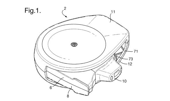
Fig. 1 is a perspective view from above of an inhaler according to at least
one
example embodiment of the invention, in an open configuration;
Fig. 2 is a perspective view from above of the inhaler of Figure 1, in a
closed
configuration;
Fig. 3 is a perspective view from below of the inhaler of Figure 1, in an open
configuration;
CA 02804959 2013-01-10
WO 2012/010878 PCT/GB2011/051350
13
Fig. 4 is a perspective view from below of the inhaler of Figure 1, with an
outer
casing component removed;
Fig. 5is an exploded perspective view of the inhaler of Figure 1;
Fig. 6 is a cross sectional view of selected components of the inhaler of
Figure 1, in
a primed condition;
Fig. 7 is a cross sectional view of selected components of the inhaler of
Figure 1, in
a fired condition;
Fig. 8 is a perspective view from below of a mouthpiece and upper outer casing
component of the inhaler of Figure 1;
Fig. 9. is a plan view from below of the cavity disc and indexing mechanism of
the
inhaler of Figure 1;
Fig. 10 is a perspective view of part of the indexing mechanism and actuator
of the
inhaler of Figure 1;
Fig. 11 is a perspective view of the mouthpiece of the inhaler of Figure 1;
Fig. 12 is a plan view from above of the lower housing, drive member (indexer)
and torsion spring; and
Fig. 13 is a perspective view of the inhaler of Figure 1 with the lower
housing and
lower cover separated, and with some components omitted for clarity.
Detailed description of the drawings
Referring to the Figures, the inhaler 2 comprises a dose dispensing assembly 4
having a general disc configuration, an upper housing portion 6 and a lower
housing
portion 8, both of 30% glass fibre reinforcement plastic (eg. polybutylene
terephtalate,
PBT). The inhaler also comprises a mouthpiece assembly, the assembly
comprising a
mouthpiece member 10 of polypropylene (e.g. Purell HM671T) with a
thermoplastic
vulcanizated elastomeric mouthpiece seal member 9 which seals the interface
between the
mouthpiece assembly and the housing. Alternatively, the seal member 9 could
for example
comprise an elastomeric member such as Santoprene 8281-45MED. The housing is
pivotally mounted within a casing comprising upper and lower outer casing
components
11, 12 of polycarbonate (e.g. Makrolon 2458); in this way the inhaler can be
moved
between open and closed configurations. In the open configuration the
mouthpiece is
exposed and an external air inlet 71 is opened up adjacent the mouthpiece (see
e.g. Figure
WO 2012/010878 CA 02804959 2013-01-
1014 PCT/GB2011/051350
1). In the closed configuration, the mouthpiece is enclosed within the outer
cover 11, 12
and the air inlet 71 is shut (see e.g. Figure 2).
The dose dispensing assembly 4 comprises a cavity disc 14 of high density
polyethylene (such as Purell GC7260) which has a plurality of cavities 16
formed in one
major face of the disc, evenly spaced around the periphery. An alternative
material for the
dose dispensing assembly 4 is polypropylene (e.g. Purell HM671T). The cavities
16
contain dry powder medicament for inhalation (not shown), and are sealed by a
laminated
film 18 of aluminium foil and polymer material (referred to as a "foil
layer"), thus
providing sealed compartments. Above each cavity 16, a respective associated
separating
ici element 20 of polypropylene is attached to the upper side of the
foil layer 18.
Alternatively, the separating element can be formed of high density
polyethylene (such as
Purell GC7260) particularly when the dose dispensing assembly 4 is
polypropylene (e.g.
Purell HM671T). The separating elements 20 are attached by any suitable type
of bonding,
welding, gluing, etc. to the respective part of the foil layer 18. Upwards
movement or
is lifting of a separating element 20 causes the attached part of the
foil layer 18 to become
separated from the cavity 16. The foil layer 18 has radial cuts between each
separating
element.
On the opposite face of the cavity disc 14 is a second annular foil layer 19
(see
Figure 13) bearing numbers 1-30 corresponding to the medicament cavities 16.
20 Underneath the cavities a space is defined extending around the
disc. This space contains a
desiccant material(either as molecular sieve or silica gel), and the second
foil layer 19 seals
the desiccant in this space. In certain states of the inhaler, one of the
numbers printed on
the second foil are visible though windows in the lower housing portion 8 and
lower cover
12. This is explained more fully below.
25 A circular guide structure 22 of of high density
polyethylene is provided above the
separating elements 20. The guide structure could alternatively be formed of
polypropylene
(e.g. Purell HM671T). The guide structure 22 comprises a plurality of guide
sections 24
divided by vertically extending walls, each guide section 24 being associated
with a
respective separating element 20. When a separating element 20 is lifted from
the cavity
30 disc 14, the associated guide section 24 will guide the upwards
movement of the separating
element 20. Each guide section 24 is provided with a blade spring 26 as part
of the
moulding. The blade spring bears downwardly on the top of the respective
separating
CA 02804959 2013-01-10
WO 2012/010878 PCT/GB2011/051350
15
element 20. After a separating element 20 has been lifted and medicament in
the opened
cavity 16 has been entrained in the inhalation airflow and the separating
element 20 has
returned to the disc 14, the blade spring 26 will keep the lifted separating
element 20 in
contact with the disc 14 to cover the cavity 16. This will make it difficult
for any remaining
powder to exit the covered used cavity 16, thus reducing the risk of dose
variation which
could occur if remaining powder were to be entrained in a following
inhalation. It also
reduces the risk of remaining powder exiting the cavity 16 and jamming
mechanical
components in the inhaler or the risk of the separating element creating a
rattling noise
which would be undesirable for the user.
The vertical walls dividing the circular guide structure 22 into guide
sections 24
function as lateral flow path defining elements. Thus, an inhalation airflow
is prevented
from deviating sideways once it reaches the cavity area of the disc 14 and
will be led to the
mouthpiece 10. An alternative would be to have shorter vertical walls, in
which case
neighbouring separating elements 20 could have the function of lateral flow
path defining
is elements.
Each separating element 20 has a cavity-covering portion 28 which is in
register
with a respective cavity 16 in the base. Additionally, each separating element
20 has a
centrally projecting portion 30, extending inwardly towards the centre of the
disc
assembly. An opening mechanism comprising an actuator 32 for lifting the
separating
elements 20 is provided. The actuator is in the form of a pivotable lever of
polyoxymethylene (POM, e.g. Hostaform MT12U01) provided with jaws 34 for
gripping
the centrally projecting portions 30 of the separating elements 20. The
actuator 32 has an
energized position in which the jaws 34 are in a lowered position and an
unloaded position
in which the jaws 34 are in a raised position. The actuator 32 does not rotate
with the disc
assembly but remains oriented towards the mouthpiece; it is pivotable around
the
horizontal hinge 36 (see Figure 10) to move between raised (fired) and lowered
(energised)
positions.
Referring to Figure 8, the upper outer cover component comprises, on its
interior
surface, a central cam 44, an elongate force transmitting member 50 and a cam
track 109.
The function of these components is explained below.
The inhaler housing (together with the mouthpiece assembly) are arranged to
pivot
with respect to the cover 11, 12 between a closed position in which the
mouthpiece 10 is
CA 02804959 2013-01-10
WO 2012/010878 PCT/GB2011/051350
16
enclosed in the cover and an open position in which the mouthpiece is exposed
for use.
The central cam 44 engages with the actuator 32 to reset it when the inhaler
is closed by
rotating the main housing 6, 8 with respect to the outer cover 11, 12. As the
cam 44 comes
into contact with the jaws 34 of the actuator 32, the actuator 32 will rotate
around its pivot
36. The jaws 34 will drop down to the primed or energized position of the
actuator 32. The
lowering of the jaws 34 will be against the force of a coil spring 46 of
stainless steel which
is biased to raise the jaws 34 to the unloaded position (although in fact the
jaws are not
totally unloaded in the raised position). The coil spring 46 is wound around a
post 48
projecting upwardly from the lower housing portion 8 and may be seen, for
example, in
io Figures 5, 6 & 7.
The force transmitting member 50 engages one end 110 of a torsion spring 52 of
stainless steel located under the coil spring 46 and around the same post 48
(see Figures 6,
7 and 12). The torsion spring 52 is connected at its other end 111 to a drive
member 54 of
polyoxymethylene (POM, e.g. Hostaform MT12U01) for rotatingly advancing the
cavities
is 16 by one increment at a time, so as each time to bring an unopened cavity
into alignment
with the mouthpiece 10. The drive member is best seen in Figures 9 and 12.
A latch 56 is provided to keep the actuator in the energized position. The
latch 56
comprises a first element in the form of a prop 58 of polycarbonate (e.g.
Makrolon 2458)
and a second element in the form of a flap 60 of polyoxymethylene (POM, e.g.
Hostaform
20 MT12U01). The prop 58 has a first end portion 62 which is pivotable around
a first
horizontal pivot 64 on the actuator 32, near the opposite end of the actuator
32 to the jaws
34. The prop 58 has a second end portion 66 adapted to be supported on a
shoulder 61 at
one end of the flap 60. The flap 60 is pivotable around a second horizontal
pivot 68 shown
in Figure 6 simply by a cross indicating the axis of the pivot; the structure
of the second
25 pivot 68 is partly shown in Figure 5, where part of the support 69 for a
corresponding pivot
pin on the flap 60 is shown.
The flap 60 covers a flap valve aperture 70 provided in the lower housing
portion 8,
which may be seen in Figure 4. Air is allowed to enter the inhaler 2 through
the aperture 70
when the user inhales through the mouthpiece 10 (outlet). The incoming air
moves the
30 flap, which in turn triggers the actuator 32 to open a cavity so that
medicament may be
entrained in the air flow. This will be explained in more detail below.
CA 02804959 2013-01-10
WO 2012/010878 PCT/GB2011/051350
17
When the inhaler is in the open configuration shown in Figs 1, 3 and 4, air
may
enter the outer casing through an external air inlet71 between the outer
casing and
mouthpiece. A first part of an inlet air flow path is thus defined between the
the outer cover
and a region 113 of the side wall of the housing (see Figure 4).
From the first part of the inlet air flow path, air then passes between the
flat internal
face of the lower cover 12 and flat external surface of the lower housing 8 to
reach the flap
valve aperture 70 defined in the lower housing portion 8 (see Figure 4). This
second part
of the inlet air flow path is defined partly by a portion 112 of the inner
surface of the lower
outer casing component 12 (see Figure 5) which is kept free from reinforcing
ribs which
could impede or obstruct flow. The second part of the inlet air flow path is
also partly
defined by a slightly recessed region 114 of the lower housing 8 leading to
the flap valve
aperture 70. Figure 4 shows the underside of the lower housing portion 8 which
has a
number of apertures formed in it in addition to the flap valve aperture 70.
One of these
apertures is a dose counter window 117 through which a dose count number
printed on the
is lower foil layer of the cavity disc becomes visible when the inhaler is in
a closed
configuration. In the closed configuration the dose counter window 117 is in
registry with
a dual purpose display window 119 in the lower casing member 12, such that the
dose
count is visible to a user. This is best understood with reference to Figure
13. Figure 2
shows the inhaler from underneath in the closed configuration, with the dose
count number
displayed in the dual purpose window 119.
Referring again to Figures 4 and 13, a "ready for use" indicator window 118 is
also
provided in the underside of the lower housing portion, though which a display
flag
component 89 on the drive member 54 may be viewed. The ready for use indicator
window comes into registry with the dual purpose display window 119 when the
inhaler is
in an open configuration, allowing the flag 89 to be viewed instead of the
dose count
number. The flag 89 has two indicia on it, one indicating that the inhaler is
ready for use,
and the other indicating that the current medicament cavity has been emptied.
The position
of the display flag changes in dependence on the state of the inhaler, so that
the appropriate
indicium is visible through the windows 118, 119. The structure and operation
of the drive
member 54 and display flag 89 will be discussed more fully below, but the
states of the
"ready for use" indicator may be understood with reference to Figures 3a and
3b which
show, respectively, the "ready" and "fired" states of the inhaler.
CA 02804959 2013-01-10
WO 2012/010878 PCT/GB2011/051350
18
When the inhaler is in the closed configuration (Figure 2), the mouthpiece
assembly 9, 10 is received into the external air inlet 71, closing off the
inlet and thereby
helping to protect both the mouthpiece and the inlet air flow paths from being
contaminated by particles of dirt.
Referring again to Figure 4, a number of apertures 116 are shown in addition
to the
dose counter and ready for use windows 117, 118. These further apertures 116
are a result
of the injection moulding process and are necessary in order for various parts
of the inhaler
to be moulded in one piece with the lower housing. A transparent membrane 115
is shown
separated from the lower housing portion 8. In the assembled inhaler the
transparent
membrane 115 is secured by adhesive to the lower surface of the lower housing
8 thereby
sealing the moulding apertures 116 as well as the windows 117,118 and helping
to prevent
leakage air flow paths. It is important to minimise leakage air flow paths
because they can
reduce the air flow in the main air channels of the inhaler when the inhaler
is used to
values below those needed for correct functioning. They can also cause
unpredictability in
is the air flow.
Because the membrane 115 is transparent, it allows the dose count and ready
for
use indicia to be viewed through the respective windows 117,118. It is
possible to prepare
the membrane 115 as a self adhesive film of polymer material, which is simple
to assemble
to the housing. The entire membrane may be coated with transparent adhesive
or,
alternatively, the portions of the membrane corresponding to the windows
117,118 may be
left free of adhesive.
Fig. 6 is a schematic cross-sectional view of selected details of the inhaler,
showing
the inhaler in a primed state with the actuator 32 latched in an energized
position. The jaws
34 of the actuator 32 have been lowered against the force of the coil spring
46. The
dispensing assembly 4 is rotated, after the jaws 34 are lowered, to bring the
next unopened
cavity 16 into alignment with the mouthpiece 10. The jaws 34 now enclose the
centrally
projecting portion 30 of a separating element 20 associated with the unopened
cavity. The
second end portion 66 of the prop 58 is supported by the shoulder 61 of the
flap 60. The
latch 56 comprising the prop 58 and the flap 60 is now in its first position,
in which it
latches the actuator 32 in the energized position. The prop 58 is biased into
the position
shown in Figure 6 by the actuator, under the influence of the coil spring 46.
The interface
or contact point between the second end portion 66 of the prop 58 and the flap
shoulder 61
CA 02804959 2013-01-10
WO 2012/010878 PCT/GB2011/051350
19
is located such that the line of action of the force exerted by the prop on
the shoulder is on
the same side of the second horizontal pivot 68 (the flap pivot) as the
portion of the flap 60
covering the aperture 70. In this way, the flap 60 is held in the illustrated
lowered position.
As long as the flap 60 remains still, the prop 58 is also prevented from
moving, keeping the
actuator 32 latched in its energized position.
In order to administer a dose, the user inhales, creating a sufficient
pressure drop
across the flap 60 to raise the flap against the biasing force. This is
illustrated in Fig. 7. As
the flap 60 is raised and pivoted around the second pivot 68 (clockwise in
Fig. 7), the flap
shoulder 61 moves to the right in Figures 6 and 7 which results in the prop
rolling off the
io shoulder 61 under the influence of the actuator spring (coil spring 46),
the prop pivoting at
its upper end around the pivot 64.
During the critical part of the movement, while the prop is being moved by the
breath flap against a biasing force, the contact between the prop and shoulder
is a rolling
contact; the prop and breath flap behave as an over-centre mechanism. This is
to minimise
is friction, which may add to the force required to trigger the mechanism and,
more
importantly, potentially cause this force to be unpredictable. During this
rolling phase of
the movement, the line of action of the force exerted on the flap shoulder by
the prop
moves from the left side of the flap pivot to the right side of the flap
pivot. Once this has
happened, the flap is no longer biased into the closed position by the prop;
pivoting of the
20 flap now continues rapidly, assisted by the force exerted by the prop under
the influence of
the coil spring 46.
The shape of the shoulder 61 is such that, when the flap reaches a certain
angle, the
prop will be pushed completely off the shoulder under the influence of the
coil spring 46.
This last stage of the movement will involve sliding friction, but the
movement is driven
25 entirely by the coil spring 46 and is independent of any movement of the
breath flap; the
coil spring is designed easily to overcome any friction between the prop and
the shoulder.
The latch 56 is now in its second position, in which the actuator 32 is free
to move
to its unloaded position under the influence of the coil spring 46. The
actuator 32 will
rotate around its pivot 36 and the jaws 34 will be raised. The engaged
separating element
30 20 which is in registry with the jaws 34 is thereby lifted from the cavity
disc 14. The
portion of the foil layer 18 associated with the cavity 16 which has been
opened remains
attached to the separating element 20. Figs. 5 and 7 illustrate one separating
element 20a in
WO 2012/010878 CA 02804959 2013-01-
1020 PCT/GB2011/051350
the raised position being raised by the jaws 34 of the actuator 32. On
inhalation, air flows
across the top of the opened cavity inducing a circulating flow in the cavity
which
deaggregates medicament powder (not shown) in the cavity and entrains it in a
flow of air
exiting the inhaler through the mouthpiece 10. Details of the process of
emptying the
cavity may be found in co-pending applications numbers PCT/SE2008/051488
(WO 2009/082341) and US 61/222209 (from which WO 2011/002406 claims priority),
incorporated herein by reference.
With the prop 58 in the un-latched position shown in Figure 7, the flap 60 is
free to
return to the lowered position after a dose is dispensed, however the actuator
32 remains in
ici the unloaded position (Fig. 7) until the user primes the inhaler for
the next dose.
Closing of the inhaler after use involves rotating the upper and lower casing
components 11, 12 (the outer cover) with respect to the rest of the device to
achieve the
configuration shown in Figure 2. As this is done, the central cam feature 44
(see Figure 8)
on the upper outer casing 11 engages with the actuator 32 to lower it and
energise the coil
is spring 46. The central cam 44 accesses the actuator 32 via an
aperture 45 in the upper
housing portion 6, best seen in Figure 5. In the closed position, the actuator
32 is retained
by the central cam 44 so that there is no possibility of a medicament cavity
being opened
whilst the inhaler is in the closed configuration.
The flap 60 has a protrusion, or flap cam 62 (see Figure 9), on its upper
surface
20 which engages with the force transmitting member 50 (see Figure 8)
which depends from
the upper casing component 12. The inter-engagement of these features retains
the breath
flap in the lowered position. The force transmitting member 50 and flap cam 62
remain
engaged as the inhaler is opened, until the fully open configuration is
reached, or nearly
reached, at which point the flap 60 is released. This arrangement is provided
to reduce the
25 possibility of the flap being deflected by an inhalation when the
inhaler is only partly open,
which may result in incorrect functioning of one or more of the other
components in the
inhaler.
As the inhaler is closed, an indexing mechanism moves the cavity disc around
to
position an unopened cavity adjacent the mouthpiece 10 and the actuator 32.
30 The indexing mechanism comprises a drive member or
indexer 54 including an
integral pawl 85, an additional pawl 86, a display flag 89 and a pulling arm
90 (also known
as an indexer link), as well as the torsion spring 52 and the mouthpiece 10.
CA 02804959 2013-01-10
WO 2012/010878 PCT/GB2011/051350
21
Figure 9 shows the cavity disc 14 and indexing mechanism from below. The
indexer or drive member 54 is shown in detail in Figure 10 together with the
additional
pawl 86, display flag 89, indexer link 90, actuator 32 and prop 58. The drive
member 54 is
a single moulding of polyoxymethylene (POM, e.g. Hostaform MT12U01) which
comprises an integral pawl 85, prop preventer arm or catch 84, display flag 89
and
mounting aperture 88. The drive member 54 is mounted via its mounting aperture
88 to the
central post 48 on the lower housing 8 (the housing and post are not shown in
Figure 9 but
may be seen e.g. in Figure 5). The additional pawl 86 is a separate moulding
(e.g. a POM
moulding), attached to the indexer 54 by a snap fit pivot connection. Both the
integral
ici pawl and additional pawl engage with or between teeth 82 on the internal
circumference of
the cavity disc 14. The indexer link 90 is also a separate moulding of
polypropylene (or
alternatively a POM moulding), attached to the indexer 54 by a snap fit pivot
connection.
The indexer link includes a hole 91 into which projects a peg 33 on the lower
side of the
actuator 32 (see Figure 10). The functioning of the indexing mechanism will be
described
is more fully below.
The mouthpiece assembly comprises a mouthpiece member 10 and an elastomeric
seal member 9. The mouthpiece member 10 is a single moulding from
polypropylene (e.g.
Purell HM671T) which comprises a main part and a pivot ring 100 on the end of
an arm
102 extending from the main part (see Figure 11). The mouthpiece assembly is
pivotally
20 mounted on a spigot 101 on the lower housing portion 8 (see Figure 5)
which passes
through the pivot ring 100. The main part of the mouthpiece assembly, best
seen in Figure
11, comprises an inhalation channel 103 and secondary bypass channels 104 on
each side.
The secondary bypass channels 104 are partly formed by the mouthpiece member
10 and
partly by the seal member 9.
25 On the side which faces the inhaler housing 6, 8, a leaf spring 106
projects
obliquely from each of the upper and lower edges. At the distal end of each
leaf spring
106 is a cam follower peg 105. The cam followers 105 and leaf springs 106 are
integrally
moulded with the mouthpiece member 10. The cam followers 105 and leaf springs
106
engage in cam tracks 109 on the inside surfaces of the respective outer covers
/ casing
30 components 11, 12. The cam track 109 on the lower casing component can be
seen in
Figure 5, whilst the cam track 109 on the upper casing component 11 can be
seen in
Figure 8.
WO 2012/010878 CA 02804959 2013-01-
1022 PCT/GB2011/051350
Projecting towards the inhaler housing 6, 8 from underneath the inhalation
channel
103 of the mouthpiece member 10 is a spacing member or locating peg 107. On
the
outside circumference of the cavity disc 14 are notches 108 (see e.g. Figure
9) into which
the locating peg 107 can project. In this way, the mouthpiece acts as a brake
on the cavity
disc to prevent indexing of the disc occurring at the wrong time in the
indexing sequence.
During the opening and closing of the inhaler, the cam followers 105 and leaf
springs 106 travel along the tracks 109 which control the movement of the
mouthpiece
towards and away from the cavity disc 14, and hence the engagement and
disengagement
of the locating peg 107 with the notches 108 of the cavity disc. In Figure 8,
the
io mouthpiece and upper casing component 11 are shown when the inhaler
is open; the leaf
spring and cam follower are in region 109a of the cam track which brings the
mouthpiece
towards the housing and cavity disc (not shown) such that the disc is braked.
A region
109b at the other end of the cam track 109 can be seen in Figure 8; in the
region 109b, the
track is further away from the disc assembly and comprises a widened portion
109c and a
is narrower terminal region 109d. When the spring and follower 106, 105
are moved into
this region of the track, in the final stages of closing the inhaler, they
enter the widened
portion 109c, which leads the cam/spring radially outwardly with respect to
the disc, and
then finally the proximal end of the leaf spring 106 engages in the narrow
terminal portion
109d of the track. The mouthpiece is thereby moved away from the cavity disc
and
20 housing and then retained securely in that position, releasing the
disc to index. This will be
explained more fully below.
The resilience of the leaf spring 106 means that the spacing member or
locating peg
107 is resiliently brought to bear against the disc 14 when in the braking
position. This
allows tolerance in the disc mounting to be taken up. The inner edge of the
disc 14 (which
25 should more correctly be called an annulus rather than a disc) bears
on a bearing flange 49
(see Figure 5) which is an integral part of the lower housing moulding 8. When
the brake
is engaged, the inner edge of the disc 14 will be biased against the bearing
flange 49 in the
region of the mouthpiece.
In this state, a precisely defined spacing 110 exists between the disc
assembly and
30 the mouthpiece assembly, through which air may pass on inhalation
into the secondary
bypass channels 104. Air may also pass through a smaller spacing 111 between
the inlet of
the inhalation channel 103 and the edge of the disc assembly. These spacings
are best seen
WO 2012/010878 CA 02804959 2013-01-
1023 PCT/GB2011/051350
in Figure 9. It is desirable for the dimensions of these spacing to be as well-
defined as
possible so that the flow patterns and flow resistance are as well-defined as
possible. This
is achieved by the spacing member 107 being biased into engagement with the
disc 14.
The smaller spacing 111 forms an annular bypass channel around the inhalation
channel inlet, which may create a "sheath" flow of air around the main flow of
particle-
laden air from the disc cavity. Since the bypass air does not have particles
of powder
entrained in it, it may be able to form a barrier between the drug particles
and the wall of
the inhalation channel, reducing the deposition of drug particles on the wall.
The wall of the upper and lower housing portions 6,8 have cutaways 5a, 5b
io respectively which together form an aperture when the housing is
assembled through
which air passes into the mouthpiece. The mouthpiece seal member 9 forms a
seal against
the housing wall around this aperture. Baffles 7 are provided on each side of
the cutaway
5a in the upper housing portion 6. The function of these baffles is to extend
across the
front of the cavities on each side of the cavity which is aligned with the
mouthpiece
is inhalation channel 103. This helps to prevent any stray powder from
a used cavity from
being entrained in the bypass flow through the secondary bypass channels 104;
air entering
the bypass channels may do so from underneath the baffles, via the cutaway 5b
in the
lower housing portion.
After a dose has been dispensed, the user closes the inhaler. Through the
rotation of
20 the outer cover or casing components 11, 12 relative to the housing
6, 8, the central cam 44
will urge the actuator 32 to move to its energized position. Thus, the jaws 34
of the
actuator 32 will move from the raised unloaded position illustrated in Figure
7 to the
lowered energized position illustrated in Figure 6.
Substantially simultaneously with the cam 44 urging the actuator 32 into the
25 energised position, the projecting second force transmitting member
50 on the upper outer
casing 12 will urge the indexing mechanism to advance the next cavity 16 to be
aligned
with the mouthpiece 10. More particularly, the projecting member 50 (see
Figure 8),
passing through the aperture 45 in the upper housing portion (see Figure 5)
engages with
the torsion spring 52 to energise it. Figure 12 shows the torsion spring 52
mounted on the
30 central post 48 of the lower housing portion 8. The spring 52 is at
rest as shown in Figure
12. A first end 110 of the spring 52 is moved clockwise (as viewed in Figure
12) by the
force transmitting member 50. A second end 111 of the spring is engaged with
the drive
WO 2012/010878 CA 02804959 2013-01-
1024 PCT/GB2011/051350
member 54. The energized torsion spring 52 will thus urge the connected drive
member
54 to rotate around the central axis provided by the post 48 in order to
engage the cavity
disc 14 and to thereby cause the disc 14 to rotate so as to bring the next
cavity 16 into
alignment with the mouthpiece 10. However, the force on the drive member 54
provided
by the projecting member 50 via the torsion spring 52 is temporarily
counteracted, at least
until the actuator 32 has reached its energized position, by the mouthpiece
brake
arrangement described above. The indexing of the disc is thereby prevented
until just
before the inhaler is closed (when the leaf springs 106 and cam followers 105
reach region
109b in the cam tracks). This arrangement prevents the mechanism trying to
index before
ici the actuator is lowered (in which case the actuator would obstruct
indexing). It also avoids
the possibility of partial indexing if the cover is partially closed and then
opened.
As illustrated in Fig. 9, before the brake is released the pawl 85 of the
drive
member 54 engages one of a plurality of teeth 82 in the disc 14. The prop
preventer 84 is in
a preventing position, engaged with the prop 58 to prevent it resting on the
flap shoulder
is 61. Thus, in this state of the inhaler, the actuator cannot become
latched in the energized
position. This reduces the risk of re-firing from the same cavity 16.
As the brake is released, the drive member 54 will move under the influence of
the
torsion spring 52 and rotate the disc 14 by one cavity. The additional pawl 86
referred to
above prevents the drive member 54 from over-rotating the disc 14, ensuring
that the
20 inhaler is indexed only one cavity at a time.
At the upper end of the prop 58 is a position-keeping projection 72 which
engages
with a steel prop spring 77 (best seen in Figure 5) mounted on the inside face
of the upper
housing portion 6. The prop spring 77 biases the prop 58 laterally against the
shoulder 61
of the flap 60. As the drive member 54 rotates the disc 14 the prop preventer
84 will be
25 removed from the preventing position, thereby allowing the prop 58
to become supported
by the flap shoulder 61 and latch the energized actuator. The inhaler is now
primed.
As previously described, when the user opens the inhaler and inhales through
the
mouthpiece 10, the flap 60 is raised so that the prop 58 comes off the flap
shoulder 61,
thereby unlatching the actuator 32. The actuator 32 will be raised under the
influence of the
30 coil spring 46 so that the jaws 34 of the actuator 32 remove the
separating element 20 and a
portion of the foil layer 18 from the cavity 16 presently aligned with the
mouthpiece 10. As
can be seen in e.g. Fig. 9, a movable pulling arm or indexer link 90 connects
the drive
CA 02804959 2013-01-10
WO 2012/010878 PCT/GB2011/051350
25
member 54 with the actuator 32. As the actuator 32 and the jaws 34 are raised
from the
primed to the fired state, the pulling arm / indexer link 90 is moved
laterally, shifting the
drive member 54 round on the post 48, such that the pawl 85 slips back over
one ratchet
tooth 82 on the disc. The prop preventer catch 84 will consequently be moved
back to its
preventing position, in which the prop 58 is prevented from engaging the flap
shoulder 61.
When the user then closes the inhaler, it will once again become primed,
following the
sequence described above.
If the user, for some reason, does not close the inhaler fully, the spring 106
and cam
follower 105 travelling in the track 109 will not reach its point of release
(the region 109b
ici of the cam track 109), and consequently the mouthpiece brake 10 will not
be released. This
in turn means that there will be no indexing. Furthermore, although the
actuator 32 is in its
energized position, it will not become latched, as latching can only occur in
connection
with indexing, as explained above ¨ until the indexer (drive member 54) moves
round, the
prop preventer 84, which is an integral part of the indexer, will prevent
latching. If the
is user then opens the inhaler again after not fully closing it, the
actuator 32 will simply move
back to its unloaded position.
The sequence of events on opening and closing the inhaler is set out in Table
1
below.
20 Table 1
Mouthpiece assembly 9,10 is enclosed by cover; external air
inlet 71 is blocked by the housing.
Closed state ¨ readyActuator 32 is energised, but held in lower position by
central
1 cam 44 on upper outer cover 11
to use
Prop 58 is spring biased into position to support actuator 32 but
actuator is not held in energised state by prop at this stage.
Prop preventer 84 on drive member / indexer 54 is disengaged
with prop.
CA 02804959 2013-01-10
WO 2012/010878
PCT/GB2011/051350
26
Brake (mouthpiece assembly) is disengaged from edge of
cavity disc.
Torsion spring 52 is partly energised, biasing disc 14 into
correct position. An unused cavity 16 in the disc is aligned with
the mouthpiece
Central cam 44 disengages from actuator 32; actuator now held
in energised state by prop 58 resting on flap shoulder 61.
Mouthpiece is exposed and external air inlet 71 adjacent
2 Open device mouthpiece is opened.
Brake (mouthpiece) is applied to prevent disc from rotating
Indexer spring 52 is relaxed as the device is opened
Flap 60 moves, dislodging prop 58; actuator 32 is triggered and
cavity lid / separating element 20 is lifted
3 Inhale Actuator 32 pulls indexer lifflc (pulling arm) 90
and the pawl 86
of the indexer / drive member 54 is ratcheted around the teeth
82 on the cavity disc. Indexer spring 52 is still relaxed.
Actuator32 is re-set against force of coil spring 46 by cam 44
on upper outer casing moving relative to actuator, closing lid
(separating element 20) on emptied cavity.
Indexer spring 52 is re-set to energised state by force
4 Start to close device transmitting member 50 on upper outer casing 11.
Brake still
applied; disc does not move
Prop preventer 84 engages flap 60 and stops actuator32 from
latching (to prevent possibility of latching the mechanism
before indexing).
Actuator32 remains in energised state ¨ no change
Finish closing device Mouthpiece is enclosed by cover and external air inlet
is
blocked by housing.
WO 2012/010878 CA 02804959 2013-01-
1027 PCT/GB2011/051350
Brake is released, allowing disc to be advanced by the indexer
under the influence of the indexer spring. Prop preventer
disengages from flap 60 to allow prop 58 to be moved against
flap 60 under influence of prop spring 77. Prop 58 is in
position to take load of spring-biased actuator when cam 44
disengages on opening.
It should be noted that in this application terms such as "upper", "lower",
"above",
"below" have been used for explanatory purposes to describe the internal
relationship
between elements of the inhaler, regardless of how the inhaler is oriented in
the
surrounding environment. For instance, in the exemplified embodiment in the
drawings,
the cavities 16 are regarded as being placed "below" the foil layer 18, while
the separating
elements 20 are regarded as being placed "above" the foil layer 18, regardless
of how the
inhaler 2 as a whole is held or turned by the user. Similarly, "horizontal"
means a direction
located in the plane of the foil layer 18 or any plane parallel to the plane
of the foil layer
18, and "vertical" means any direction perpendicular to such planes. Thus, a
vertical line
may intersect the cavities 16, the foil layer 18 and the separating elements
20.