Note: Descriptions are shown in the official language in which they were submitted.
WO 2012/009375 CA 02805197 2013-01-11 PCT/US2011/043741
Electromagnetic Orientation System for Deep Wells
Cross Reference to Related Applications
[0001] This application claims the benefit of US Provisional Patent
Application
No. 61/363,879, of Arthur F. Kuckes, filed July 13, 2010, and entitled
"Electromagnetic Orientation System for Deep Wells," the disclosure of which
is
hereby incorporated herein in its entirety by reference. This application is
also
related to US Patent Application Publication No. U52010/0155138 Al (the '138
publication), the disclosure of which is also hereby incorporated herein by
reference.
Background of the Invention
1. Field of the Invention
[0002] The present invention relates, in general, to methods and apparatus
for
locating the distance and direction to a conductive target, such as a cased
well or
borehole, from a remote location such as a rescue borehole or well to obtain
data for
use in guiding the direction of drilling the rescue well to intersect the
target, and to
methods and apparatus for injecting time-varying electrical currents into the
earth
from one or more electrodes in the rescue borehole, for detecting at the drill
bit of the
rescue well electromagnetic field vectors resulting from such injected
currents
flowing in the target, and for transmitting data representing the detected
fields to the
earth's surface. More particularly, the invention relates to a method and
apparatus
for guiding the drilling of a borehole when the rescue well is traveling in a
direction
very close to vertical and the direction of gravity almost coincides with the
direction
of drilling.
2. Description of the Related Art
[0003] It is well known that in drilling boreholes in the earth, such as
deep
wells for oil and gas exploration, precise control of the path followed by the
well is
extremely difficult, so that it is virtually impossible to know the exact
location of the
well at a given depth. For example, a drilling tolerance of plus or minus one
quarter
of a degree will allow the bottom of a 10,000-foot well to be positioned
anywhere
within a circle 100 feet in diameter, and numerous factors can increase the
deviation.
This is not of particular concern in many drilling operations, but if drilling
precision is
necessary, as where a borehole is to be drilled precisely to a target
location, such
variations can cause severe difficulties. One example of the need for
precision
drilling occurs in the situation where it becomes necessary to drill a relief
well to
1
WO 2012/009375 CA 02805197 2013-01-11PCT/US2011/043741
intersect an existing deep well, as in the case where the casing of the deep
well has
ruptured and it becomes necessary to plug the well at or below the point of
the
rupture to bring it under control. In order to do this, the relief well must
be drilled to
intersect the original well at the desired level, and since such ruptures, or
blowouts,
often produce extremely hazardous conditions at the surface in the vicinity of
the
original well, the relief well usually must be started a considerable distance
away
from the original wellhead and drilled at an incline down to the desired point
of
intersection.
[0004] Because the same problems of control of the direction of drilling
that
were encountered in the original well are also encountered in drilling the
relief well,
the location of the relief well borehole also cannot be known with precision;
accordingly, it is extremely difficult to determine the distance and direction
from the
end of the relief well to the desired point of intersection on the target
well. In addition,
the relief well usually is very complex, compounding the problem of knowing
exactly
where it is located with respect to a target that may be 10 inches in diameter
at a
distance of thousands of feet below the earth's surface.
[0005] Numerous early attempts were made to solve the problem of guiding a
relief well to accurately intersect a target well. Some utilized surveying
techniques to
locate the relief well with respect to a target well, but such survey
techniques are not
capable of providing accurate data concerning the relationship of the relief
well to the
original well until the relief well has approached very near the original
well. Magnetic
gradient ranging equipment can be used with considerable accuracy at close
range;
however, it has been found that outside a radius of a few tens of feet, such
systems
are usually inadequate.
[0006] In an attempt to extend the distance at which accurate information
can
be obtained, a variety of electrical well logging techniques have been used
which
treat the target well as an anomaly in the geologic structure of the earth
surrounding
the relief well. Some of these systems are directed to the measurement of the
apparent resistivity of the earth across a pair of electrodes but, since no
directionality
is given by this method, it is ineffective for directing a relief well toward
an existing
well.
[0007] In addition, there have been attempts to obtain similar data through
the
use of electromagnetic prospecting, where induction sensing coils mounted at
right
2
WO 2012/009375 CA 02805197 2013-01-11PCT/US2011/043741
angles to each other are used in conjunction with other conventional well
logging
systems to determine the probable location of a target. However, such systems
do
not suggest the possibility of locating relatively small targets such as well
bores.
[0008] Other systems have been developed for directing a second well with
respect to a first well by the use of sonic detectors responsive to the sound
produced
by fluids flowing out of a blown well formation. However, such systems will
not
operate when there is no sound emanating from the target well, and, in
addition, do
not provide the required degree of directional and distance accuracy. Another
proposal in the prior art is the use of a signal transmitter in one well and a
signal
receiver in the other well, wherein sound waves or magnetic fields may be used
as
the signals. In these latter systems, however, the target well must be
accessible so
that the signal source can be placed in one well and the receiver in the
other, and
they are not effective where the target well is not open.
[0009] Many of the difficulties outlined above were overcome in the prior
art by
methods and apparatus disclosed, for example, in U.S. Patents Nos. 4,323,848,
4,372,398, 4,700,142, and 5,512,830, all issued to Arthur F. Kuckes, the
applicant
herein. In accordance with such prior art patents, an electric current flow is
produced in a target such as the casing of a target well by injecting a low
frequency
alternating current into the earth surrounding the target well through the use
of an
electrode located in the relief well, or borehole. This current flow extends
between
the downhole electrode and a second electrode that may be located at the
earth's
surface in the vicinity of the head of the relief well. The injected earth
current finds a
path of least resistance through the casing or other current-conducting
material in
the target borehole, and the resulting concentration of current produces a
characteristic magnetic field surrounding the target well which can be
detected by an
AC magnetic field sensor such as that described in U.S. Patent No. 4,323,848,
or by
multiple sensors, as described in U.S. Patent No. 5,512,830. These sensors are
extremely sensitive to very small magnetic fields, and accurately detect the
vectors
of magnetic fields produced by currents flowing in well casings located a
considerable distance away from the relief borehole.
[0010] The vector signals obtained from the AC magnetic field sensors, in
accordance with the aforesaid patents, permit calculation of the direction and
distance to the target well casing with respect to the location of the AC
magnetic field
3
WO 2012/009375 CA 02805197 2013-01-11 PCT/US2011/043741
sensor in the relief well. This information can be used to guide further
drilling of the
relief well. Thus, as the relief well approaches a desired depth, its approach
to the
location of the target well can be guided so that the target well is
intersected at the
desired depth below the earth's surface in a rapid and effective manner. This
method
of guiding a relief well to intersect with a target is a homing-in process,
wherein
multiple measurements - often after every 50 feet of drilling - must be made
as the
relief borehole approaches the target, so that more time is spent measuring
than is
spent drilling. This need for making so many measurements makes the drilling
of a
relief well very expensive, especially in off-shore drilling, wherein, using
the prior
methods, the drill string for the relief well must be pulled for each
measurement.
[0011] The foregoing systems are widely, and successfully, used; however,
each of them requires a periodic withdrawal of the drill string so that
suitable sensors
and electrodes for generating the ground current can be lowered into place and
so
that distance and direction measurements from the relief well to the target
can be
obtained. Since a drilling rig operation can cost upwards of $500,000.00 per
day in
offshore drilling operations, the time-consuming process of halting the
drilling,
withdrawing the drill string, and positioning the measuring equipment is an
extremely
expensive procedure Accordingly, a method and apparatus for making such
measurements without the effort and expense of pulling the drill string is
needed.
[0012] Furthermore, in a typical borehole drilling operation, the path of
the
borehole, which may be a relief well as described above, is tracked during
drilling by
a "measurement while drilling" (MWD) instrument that is mounted near the
bottom of
the drill string. Usually, such a string consists of a series of steel tubes,
each about
meters in length and connected end-to-end. Connected at the bottom end of the
drill string is a non-magnetic section which carries the MWD instrument, and
below
that, a hydraulic drilling motor having a bent housing to which the drill bit
is
connected via a drill shaft, with each of the non-magnetic section and the
bent
housing being about 10 meters in length. As a result of this, the MWD
instrument is
typically located 10 ¨ 20 meters above the face of the drill bit, so that when
magnetic
field measurements are made with the drill string in the relief well, they are
actually
made a considerable distance from the drill bit, introducing a significant
error in
determination of the relative distance and direction of the target with
respect to the
4
WO 2012/009375 CA 02805197 2013-01-11PCT/US2011/043741
drill bit. This greatly increases the difficulty of accurately controlling the
intersection
of the borehole being drilled with the target.
[0013] Accordingly, there was a need for a measurement system that will
significantly increase the accuracy of distance and direction calculations in
drilling,
while reducing the cost of making such calculations.
[0014] Prior U.S. Patent Application Publication No. US2010/0155138A1,
referenced above, is directed to an improved method and apparatus for
determining
the distance and direction from the drill bit of a relief well drill string to
a target
location, such as the center of an existing borehole casing, without the need
to
withdraw the drill string to make the necessary measurements, while still
making the
measurements from the bottom of the relief well so that accurate calculations
can be
made. In accordance with one aspect of that invention, the need for pulling a
drill
string in order to make magnetic field measurements in a relief well, or
borehole, is
obviated by the use of magnetic field sensors mounted in a drill bit
instrument
package that is secured to the drill bit, in combination with a drill string
wireline
having a suitable current-injecting electrode and a wireline instrument
package which
can be dropped down through the center of the drill string whenever a
measurement
is to be made. The electrode is energized with a time-varying current to
produce a
corresponding magnetic field generated by current flow in the target, and the
drill bit
instrument detects that magnetic field at the drill bit. The drill bit
instrument transmits
data representing the measured field vectors, and the wireline instrument
package
receives that data and transmits it to the surface for use in guiding further
drilling.
The wireline is then withdrawn, and drilling can be resumed.
[0015] The foregoing process is carried out, in accordance with another
aspect of that invention, by a modified drill string structure having at least
one
insulating segment, but preferably two such segments, spaced apart to
electrically
isolate a selected conventional tubular, electrically conductive, steel drill
string pipe
section near the bottom of the string to form a drill string electrode. These
pipes are
generally about ten meters in length and are joined end-to-end, with sections
being
added to the drill string as drilling progresses. Each insulating segment, or
sub, is
about one meter in length, so that a single sub is generally sufficient for
electrical
isolation, although additional subs may be used, as needed. The drill string
preferably includes a single such electrode section, although in some
circumstances
5
WO 2012/009375 CA 02805197 2013-01-11PCT/US2011/043741
it may be desirable to include two spaced electrode sections separated and
isolated
from each other by at least one insulating sub. If desired, they may be spaced
further
apart by including one or more non-electrode steel pipe sections between the
insulating subs for the electrode sections. The modified drill string includes
a
nonmagnetic segment, in which is mounted a conventional MWD instrument, and
the
lowermost (distal) end of the drill string is a standard rotating drill bit
connected to the
shaft of a standard hydraulic drilling motor incorporating, in a preferred
form of the
invention, a bent housing for directional drilling control, in known manner.
As is
known, the drilling motor may be driven by drilling fluid that flows down the
center of
the drill string and back up the borehole outside the string.
[0016] When a magnetic field measurement is to be made using the drill
string
of the invention disclosed in the '138 publication, drilling is halted, and
instead of
withdrawing the drill string, a wireline carrying a wireline electrode is
lowered through
the center of the drill string until the wireline electrode is aligned with
the
approximate center of the corresponding isolated steel drill pipe electrode
section.
The wireline electrode is in electrical communication with its corresponding
isolated
steel drill pipe electrode section which is, in turn, in electrical
communication with the
surrounding earth formations. When the wireline is energized, the drill pipe
electrode
injects current from the wireline electrode into the surrounding formations
and a
portion of that current is then collected in the target. The electrodes are
energized by
a periodic time-varying current, such as a sinusoidal AC supplied from a power
supply at the earth's surface, to produce a characteristic target current and
corresponding target magnetic field. The wireline electrode is immersed in the
drilling
fluid, which may be electrically conductive to provide electrical
communication
between it and its corresponding drill pipe electrode. In the case where a non-
conductive drilling fluid is used, spring-loaded contacts may be employed on
the
wireline electrode to provide a positive electrical contact with the inner
surface of the
isolated steel drill pipe section.
[0017] In accordance with the '138 publication, the desired magnetic field
measurements are made at the drill bit sensor, or magnetic field detector,
that is
located in the drill bit instrument package described above. This location for
the drill
bit sensor is advantageous, because it is close to the actual location of the
drill bit
that is to be controlled. The drill bit instrument is battery-operated, and in
addition to
6
WO 2012/009375 CA 02805197 2013-01-11PCT/US2011/043741
suitable magnetic field vector detectors and gravity vector detectors, it
incorporates
suitable electromagnetic telemetry, such as an electromagnetic solenoid, for
transmitting data from the drill bit sensor instrument to the wireline
instrument in the
drill string. The wireline instrument includes suitable telemetry to remotely
receive
the data from the drill bit sensor and to transmit that data to the surface.
[0018] In another embodiment of the invention described in the
aforementioned '138 publication, magnetic field measurement accuracy may be
improved in some circumstances by operating the system in a pulsed transient
mode, wherein the earth formations surrounding the relief and the target wells
are
energized by a stepped, or pulsed, primary excitation current from a power
source
which preferably is at the surface, and measurements of magnetic fields
produced by
the resulting current flow in the target are made immediately following a
stepwise
turn-off of the excitation current, when that current is zero. Each pulse of
electrical
energy supplied to the wireline electrode causes a current to flow through the
earth's
formations to the target, and, as described in the foregoing U.S. Patent No.
4,700,142, this current is collected on the electrically conductive target.
The resulting
target current flow creates a characteristic target magnetic field that is
detected by
the drill bit sensor instrument. In the pulsed, or transient, mode of
operation of the
device, the magnetic field measurement is made after the primary energizing
current
stops. The magnetic fields that are measured when the excitation current is
zero are
caused by a decaying target well current flow. Although this decay current
produces
only a very small field, since even the primary target current typically is
only a few
percent of the energizing current, the measurement of the decay field is more
accurate, since interfering fields caused by the primary electrode current in
the earth
are not present.
[0019] To enhance this transient pulsed current magnetic field measurement,
the drill string incorporates at least two spaced, electrically isolated
conductive drill
string pipe sections, each separated from each other and other adjoining pipe
sections by one or more electrically insulating subs. Deep well measurements
are
made by aligning corresponding spaced-apart wireline electrodes with the
approximate centers of corresponding isolated drill pipe sections to
effectively
produce two drill pipe injection electrodes spaced along the drill string
above the drill
motor, by supplying a time-variable current to the electrodes to inject a
current in the
7
WO 2012/009375 CA 02805197 2013-01-11PCT/US2011/043741
earth and producing a corresponding time-varying target current, and by
detecting
the resulting target magnetic field vectors at the location of a drill bit
sub. Telemetry
at the drill bit sub transmits the detected vector data uphole for use in
calculating the
distance and direction from the drill bit sub to the target.
[0020] The invention disclosed in the referenced '138 publication has proven
to be very important for the drilling guidance of relief wells to intersect
and to stop the
uncontrolled flow of oil in a blowout well. As described above, a crucial
element of
that invention is to determine the direction to a "blowout" oil well from the
relief well
being drilled to enable proper adjustments to the direction of drilling, and
this is done
by orienting the electromagnetic instruments relative to the borehole using
accelerometers to define the orientation of the plane defined by the direction
of
drilling and the direction of gravity, i.e., the vertical axis. However, when
the relief
well is very close to vertical and the direction of gravity almost coincides
with the
direction of drilling this method for tool orientation fails.
Summary of the Invention
[0021] The present invention relates to an electromagnetic method and
apparatus for solving the above-described problem. In addition to relief well
drilling
applications involving the '138 publication drilling method and apparatus, the
present
invention is useful whenever relative orientations must be determined remotely
and
where the measurements are to be made when the measuring apparatus is very
close to vertical and the direction of gravity almost coincides with the
direction of that
apparatus.
[0022] Briefly, the present invention is directed to an electromagnetic
method
and apparatus for determining the azimuthal orientation of a drill bit
instrumentation
sub, with respect to a borehole drilling assembly, where the axis of the
instrument
sub coincides with the direction of drilling. In accordance with a preferred
embodiment of the invention, a dipole electromagnetic field source is fastened
to the
drilling assembly so as to produce an auxiliary alternating electromagnetic
field
having a dipole axis that is perpendicular to the borehole axis. The direction
of the
field lines generated by this magnet is measured by electromagnetic field
sensors in
the drill bit instrument sub. When such a source is used, for example, in
conjunction
with the apparatus of the '138 publication to determine the direction from a
relief
borehole to a target blowout well, simultaneous measurement of an
electromagnetic
8
WO 2012/009375 CA 02805197 2013-01-11PCT/US2011/043741
field generated by current flow in the blowout well casing and the direction
of the
auxiliary field produced by this electromagnet makes it possible to determine
the
direction to the blowout with reference to the direction of drilling without
using an
intermediate parameter such as, for example, the direction of gravity or of
the Earth's
magnetic field.
[0023] In accordance with a preferred embodiment of the invention, an
auxiliary AC magnetic field source, such as a tiny AC solenoid, is located at
or near
the drilling motor, immediately above a drill bit instrument package, with the
axis of
the auxiliary AC field being aligned with the "tool face" bend in the drilling
motor so
that the field axis is perpendicular to the drilling axis. The strength of
such an
auxiliary electromagnetic field source can be miniscule since it is close to
the
electromagnetic sensors in the drill bit instrument sub. Accordingly, the
electric
power required is such that this field source can be powered continuously by a
small
battery during the entire time that the drill bit is in the borehole so the
difficult
problem of remotely switching it on when needed and off otherwise is
eliminated.
The drill bit instrument package in the instrumentation sub incorporates a
sensor
package including a three-component AC magnetometer for measuring the x, y and
z components of the target electromagnetic field that is generated by current
flow
produced on a target such as a well casing of a blow-out well. These sensors
also
respond to the auxiliary AC field generated by the solenoid fastened to the
drilling
assembly near the drilling motor. The magnetic field generated by this
solenoid has a
different frequency than that of the low-frequency current that produces the
target
well field, so that signal averaging electronics in the instrument package can
separate the two signals. This instrument package is programmed to accommodate
the processing of the two measured electromagnetic fields of different
frequencies to
produce individual measurement signals which are sent up hole by an
electromagnetic communication link.
[0024] The axis of the drill bit instrumentation package is aligned with the
drill
head and thus with the direction of drilling, and the azimuthal angle between
the
direction of the auxiliary field at the instrumentation package and the
direction of the
instrument package is known from the mechanical construction of the auxiliary
field
dipole source. Measurement of the target electromagnetic field gives the
azimuthal
direction to the target well with respect to the instrument package; however,
the
9
WO 2012/009375 CA 02805197 2013-01-11PCT/US2011/043741
azimuthal direction of the drilling motor axis with respect to the target
field is not
precisely known, and cannot be determined by the usual gravity measurements
when the borehole being drilled is nearly vertical. In accordance with the
present
invention, measurement of the direction of the auxiliary magnetic field at the
drilling
motor instrument package gives the orientation, or relative rotation angle, of
the drill
bit instrument sub with respect to the target magnetic field. These measured
fields
are then combined to determine the azimuthal angle between the direction of
the
drilling tool face and the target well, which is the angle required to adjust
the drilling
direction to intersect the target well. Although the absolute direction to the
target well
is not determined by these measurements, the information needed to adjust the
drilling direction is.
[0025] In the preferred embodiment of the present invention, the auxiliary
electromagnetic field source is made as an integral part of the drilling
motor, and is
located below the bend in the drill motor sub so that the axis of the
auxiliary field is
perpendicular to the axis of rotation of the drill face. In such a case, the
dipole field
normally will be mechanically aligned with the direction of the bend in the
drill motor
sub. However, in an alternative embodiment of the invention, the auxiliary
electromagnetic source may be a separate component of the bottom hole drilling
assembly, instead of being a part of the drilling motor. In this case, the
auxiliary
source is installed in a separate drill string sub behind (that is, above) the
drilling
motor sub. If such a separate drill string sub is used to carry this auxiliary
source, the
orientation of the dipole source with respect to the motor drill bend is not
built into the
motor structure, and thus the connection between the subs must be controlled
so
that this angle is known. In this latter case the auxiliary AC field source
may be too
far away from the magnetic field sensors to allow it to be continuously
battery
operated, so the source may be powered and controlled from a data receiving
instrument package located above the drilling sub, as from a wire line system
going
to the surface, or from a Measurement While Drilling (MWD) instrument located
in
the drill string, as described in the '138 publication.
Brief description of the drawings
[0026] The foregoing, and additional objects, features and advantages of the
present invention will become apparent to those of skill in the art from a
10
WO 2012/009375 CA 02805197 2013-01-11PCT/US2011/043741
consideration of the following detailed description of preferred embodiments,
as
illustrated in the accompanying drawings, in which:
[0027] FIG. 1 is a diagrammatic illustration of a prior art electromagnetic
target
location system;
[0028] FIG. 2 is a graph illustrating target current flow amplitude in the
system
of FIG. 1;
[0029] FIG. 3 is a diagrammatic illustration of the prior wire line electrode
system described in US Published Application No. 2010/0155138;
[0030] FIG. 4 is a circuit diagram of sensor circuitry for the system of FIG.
3;
[0031] FIG. 5 is a circuit diagram of a wireline instrument package for the
system of FIG. 3;
[0032] FIG. 6 is a diagrammatic illustration of the orientation system of the
present invention, having an auxiliary alternating magnetic field source
mounted on a
drill motor housing near a drill bit instrument;
[0033] FIG. 7 is a diagrammatic illustration of an end view of the
relationship
of target and auxiliary magnetic fields;
[0034] FIG. 8 is a diagrammatic illustration in partial cross-section taken
along
line 8-8 of FIG. 9, showing the auxiliary alternating magnetic field source of
the
present invention mounted on a simulated drill motor housing as part of a test
setup
to evaluate the feasibility of the present invention;
[0035] FIG. 9 is an end view of the apparatus of FIG. 8;
[0036] FIG. 10 is a graph of Hx1 and Hx2 signals recorded by a drill bit
instrument sub as it is rotated with respect to the auxiliary alternating
magnetic field
source of FIG. 8;
[0037] FIG. 11 is a graph of the Hy1 and Hy2 signals recorded by a drill bit
instrument sub as it is rotated with respect to the auxiliary alternating
magnetic field
source of FIG. 8;
[0038] FIGs. 12 - 14 illustrate top, side and end views of a standalone drill
string sub which incorporates an alternating magnetic field source for
orienting a drill
bit instrument sub in accordance with another embodiment of the invention;
[0039] FIG. 15 is a diagrammatic illustration of the relative separation of a
standalone alternating magnetic field source mounted directly above a
representative
11
WO 2012/009375 CA 02805197 2013-01-11PCT/US2011/043741
drilling motor and a drill bit instrument which is mounted on the rotating
shaft of the
drilling motor;
[0040] FIG. 16 is a diagrammatic illustration showing an alternating magnetic
field source which is an integral part of an MWD system; and
[0041] FIG. 17 Is a diagrammatic illustration showing an alternating magnetic
field source which is an integral part of a wire line receiver unit which is
set into an
orienting plate which is part of the drill string.
Description of Preferred Embodiments
[0042] FIG. 1 illustrates, in diagrammatic form, a standard well locating
system 10 such as that described in U.S. Patent No. 4,700,142, the disclosure
of
which is hereby incorporated herein by reference. In such a system, a target
well 12
is to be intersected by drilling a relief borehole, or well, 14 along a path
that will
intersect the target at a desired depth below the earth's surface 16. The
target well is
cased, or has a drill string or other electrically conductive material in it,
so that
electrical current flowing in the earth's formations 18 surrounding the well
12 will tend
to be concentrated on that conductive material. An alternating electrical
current is
injected into the earth by an electrode 20 carried by a logging cable or
wireline 22,
which is lowered into the relief borehole 14 after the drill string that is
used to drill the
relief borehole has been pulled out. The electrode is connected through
wireline 22
to one side of an AC source 24, the other side of which is grounded at 26 to
the
earth. The electrode 20 contacts the uncased sides of the relief well so that
current
from source 24 is injected into the earth formations 18, as illustrated by
arrows 30.
[0043] This injected current, which returns to the grounded side of the
generator at 26, finds a path of least resistance through the casing or other
conductive material in target well 12, producing a target current flow
indicated by
arrows 32 and 34, respectively, above and below the depth of the electrode 20.
The
upward current flow of current 32 is illustrated in FIG. 2 by curve 32', while
the
downward flow of target well current 34 is illustrated in FIG. 2 by curve 34'.
As
illustrated, at the depth of the electrode equal and opposite currents on the
target
produce a net zero target current, while above and below that point the target
currents maximize and then decline due to leakage into the surrounding
formation,
as illustrated in FIG. 2, with these target well currents eventually returning
to the
ground point 26 through the earth.
12
WO 2012/009375 CA 02805197 2013-01-11PCT/US2011/043741
[0044] The concentrated current flow on the target well produces, for the
downward current 34, for example, a corresponding AC magnetic field 36 in the
earth surrounding the target well. This target AC field is detectable by an AC
field
sensor, or sonde, 40 that is suspended in the relief well 14 by the wireline
22. The
sonde 40, which preferably is located below the electrode 20, incorporates
suitable
field component detectors, such as three orthogonal magnetometers, to measure
the
vector components of magnetic field 36 and to produce corresponding data
signals
that are transmitted via the wireline to, for example, a computer 42 at the
surface.
[0045] Vector signals obtained from the magnetometers in the sensor 40,
together with measurements of other parameters such as the orientation of the
sensor, permit calculation of the direction and distance of the target well
casing from
the sensor, as described, for example, in U.S. Patents Nos. 4,700,142 or
5,512,830.
In the course of drilling the relief well, the drill string is withdrawn
periodically and the
wireline is lowered into the relief borehole so that vector measurements and
measurements of the orientation of the sensor within the borehole can be made.
These measurements, together with measurements of the relief well direction
made
either at the same time or from previously made borehole survey data, permit a
continuous calculation of the presumed location of the target well with
respect to the
location of the relief well. The wireline is then withdrawn and the drill
reinserted into
the relief well, and the calculated information is used to guide further
drilling of the
relief well. As the relief well approaches the desired depth, its approach to
the
location of the target well can be guided so that the target well is
intersected at the
desired depth below the earth's surface.
[0046] Such prior systems require the withdrawal of the drill string from the
relief well in order to measure the target magnetic field. The system of prior
publication US 2010/0155138, referenced above, allows target field
measurements
without requiring the withdrawal of the relief drill string, and is
illustrated at 50 in FIG.
3, to which reference is now made. In this system, a relief borehole, or well,
52,
which is illustrated in dashed lines, is produced by a drill carried by a
drill string 54
which, in conventional manner, is suspended from a surface drilling rig (not
shown).
Such a drill string typically consists of multiple drill string sections of
steel pipe, such
as the illustrated sections 56, 57, 58 ... 59, each normally about ten meters
in length
and coupled together end-to-end at threaded joints. In a conventional manner,
the
13
WO 2012/009375 CA 02805197 2013-01-11PCT/US2011/043741
bottom, or distal end, of the drill string incorporates a standard hydraulic
drilling
motor 62 in a bent housing 64, with the motor having a rotating drive shaft 66
connected to a drill bit 68. The drill bit carries a drill bit instrument sub
70 which is
secured to and rotates with the drill bit. Located in the drill string 54 just
above the
drilling motor housing 64 is a conventional measurement-while-drilling (MWD)
measurement system for producing a log of the drilling and for use in
controlling the
direction of drilling.
[0047] At least one of the electrically conductive drill pipe sections; for
example section 57, is electrically isolated from adjacent drill pipe sections
to form a
pipe electrode for use in injecting current into the surrounding earth
formations. This
pipe electrode 57 is formed by inserting one or more electrically insulating
subs 71
and 72, which may be short insulating pipe sections about one meter in length,
in the
drill string above and below the drill pipe section 57 that is to be isolated,
as
illustrated in FIG. 3. The insulating sub 71 is threaded to the bottom of
standard steel
pipe section 56 at threaded joint 74, and to the top of standard steel pipe
section 57,
at threaded joint 76, to space and electrically insulate the adjacent pipe
sections 56
and 57 from each other. The second insulating sub 72 is threaded to the bottom
of
the steel drill pipe section 57 at threaded joint 78 and to the top of the
next adjacent
steel drill pipe section 58 at threaded joint 80. Sub 72 separates, and
electrically
insulates, adjacent steel pipe sections 57 and 58 from each other, thereby
electrically isolating pipe electrode section 57 from the remainder of the
drill string.
[0048] Connected below the isolated drill pipe electrode section 57 are one
or
more additional steel drill pipe sections such as sections 58 ... 59, the
number of drill
pipe sections being selected to position the electrode section 57 at a desired
distance above the drill bit. A suitable distance between the pipe electrode
section
57 and the drill bit 68 may be about 70 meters.
[0049] The lowermost end of the bottom drill pipe 59 is connected at a
threaded joint 81 through an electrically insulating sub 82 and a threaded
joint 83 to
a nonmagnetic drill pipe section 84, the lower end of which is connected at
threaded
joint 86 to the top of drilling motor bent housing 64. A standard MWD
instrument in
an MWD housing 88 is located within the nonmagnetic pipe section 84 to allow
the
MWD equipment to detect surrounding magnetic fields during drilling and to
space
the drill pipe electrode 57 at the desired distance above the drill bit
instrument sub70.
14
WO 2012/009375 CA 02805197 2013-01-11PCT/US2011/043741
[0050] Located within the drill string 54 is a wireline 90, which is
suspended
from the earth's surface at the drill rig. During pauses in the drilling
operation, the
wireline is lowered into the relief well down through the central, axially-
extending
opening of the drill string. The drilling fluid flows through this axial
opening to drive
the motor 64, so the opening effectively terminates at the top of the motor.
The
wireline incorporates both power cables for injecting AC current into the
earth and
data cables for connecting down-hole instruments with the surface, and is
covered
by an insulating material such as an electrically insulating layer of a
plastic such as
HYTREL for protection from the harsh environment. The power cable in the
wireline
is connected to an electrode 92 which is uninsulated and is located on the
wireline
for electrical communication with the interior of the isolated drill pipe
section 57. This
electrode may physically contact the interior of section 57 by way of spring-
loaded
contacts, or a good electrical connection can be made through the drilling
fluid, or
drilling mud, if it is electrically conductive, since this fluid remains
within the drill
string during this process. Electrode 92 is accurately located centrally along
the
length of the drill string electrode section 57 simply by measuring the depth
of the
drill string.
[0051] The data cable in the wireline is connected to an instrument package
94 that is secured to the distal end of the wireline, below the electrode 92,
with the
wireline being long enough to locate this package centrally within the
nonmagnetic
sub 84. The power cable in the wireline is connected at the surface to a
suitable
source 24 (FIG. 1) of a periodically varying current such as a low-frequency
AC to
produce alternating current 96 in the cable, while the data cable is connected
to
suitable control circuitry at the surface, such as a computer 42 (FIG. 1).
[0052] Magnetic field and other sensors are provided in a drill bit sensor
instrument package 102 mounted on the drill bit sub 70. The instrument 102 is
illustrated in FIG. 4 as incorporating a three-component AC magnetometer
including
magnetometers 103, 104 and 105 for measuring x, y and z vector components,
respectively, of the varying electromagnetic field H that is generated by
current flow
on a target such as a well casing (see FIG. 1). These magnetometer components
may be constructed using coils surrounding U-shaped cores in accordance with
the
teachings of U.S. Patent No. 4,502,010, for example. The instrument 102 also
contains an orientation package 106 for determining the orientation of the AC
15
WO 2012/009375 CA 02805197 2013-01-11PCT/US2011/043741
magnetometers, and thus may contain two-component or three-component
accelerometers, a one-component gyroscope and a 3-component earth field DC
magnetometer for detecting vector components of the apparent Earth's field.
Apparent Earth field measurements can also be used to determine the static
magnetic field generated by the target well and thus the relative location of
the target
well using well known methods of static field analysis.
[0053] The drill bit instrument sub 102 also has an AC voltage detector 107
to
measure the polarity and magnitude of the electric field in the nearby Earth
and thus
to provide a direct measurement of the sense of the AC current flow on the
target
well relative to the AC magnetic fields Hx1, Hx2, Hy1, Hy2, and Hz. With a
symmetric AC current waveform on the target well there may be some ambiguity
in
the sense of the current flow which is removed by this measurement. This sign
ambiguity can also be determined by including an even time harmonic component
to
the AC current injected into the formations. In many cases this ambiguity also
can be
removed by well known, indirect means such as by noting the character of
measurements at other nearby depths.
[0054] The magnetometer components, the orientation package, and the AC
amplifier are connected to a down-hole control computer 108 in the instrument
102
for preliminary processing of received data and the computer is, in turn,
connected to
a communications solenoid coil 110 for wirelessly transmitting data to the
wireline
instrument package 94. Although such solenoids have a limited communication
range when used underground, sufficient power is provided by a battery pack
112 to
provide reliable data communication between the drill sub instrument 102 and
the
wireline instrument 94, which is normally less than about 30 meters distant.
In order
to preserve power, the computer 108 contains control circuitry that responds
to the
presence of output signals from the magnetometers in response to magnetic
fields
generated in the target, to turn the instrument off when it is not being used,
and on
when field measurements are to be made.
[0055] The main wireline instrument package 94, illustrated in FIG. 5, is
carried at the end of the wireline 90, and incorporates a control computer 124
connected to a suitable electromagnetic communication circuit 126, which may
be a
solenoid, for receiving data from the drill bit instrument 102, and for
controlling the
16
WO 2012/009375 CA 02805197 2013-01-11PCT/US2011/043741
operation of instrument 102. This computer 124 also is connected to computer
42 at
the surface through telemetry 128 and a data cable 129 carried by wireline 90.
[0056] Drilling of a relief borehole is carried out, for the most part, in
the
known manner illustrated in FIG. 1, but using the drill string structure
described with
respect to FIGs. 3-5. Drilling fluid flows down through the center of the
drill string 50
to provide driving power for the hydraulic drilling motor 62, and the
direction of
drilling is controlled by turning the drill string so that the borehole will
be drilled in the
direction faced by the bent housing and the drill bit. The drill bit
instrument 102 in sub
70 rotates with the drill bit, but is turned off during drilling, while the
MWD system 88
controls the drilling operation in known manner.
[0057] In order to precisely measure the distance and direction from the
drill
bit to the target to permit accurate guidance of further drilling, the
drilling is stopped,
and the wireline 90, with at least the first electrode 92 and with its
instrument
package 94, is lowered down the center of the drill string. If necessary, the
drilling
fluid can be pumped to assist in carrying the wireline down the drill string.
The
instrument 94 is lowered into the nonmagnetic sub 84 so that the wireline
electrode
92 is positioned in its corresponding drill pipe electrode section 57. The
electrodes
are in effective electrical contact with each other, so that when power is
supplied
from source 24, the drill pipe section 57 acts as an injection electrode for
injecting
electrical current into the earth surrounding the borehole. Although the power
supply
is preferably a low-frequency AC source, as described above, a DC source may
be
used if desired, with down hole switching providing alternating or pulsed
current to
the surrounding earth formations. The pipe section 57 produces current flow in
the
earth by contacting the earth directly or through the drilling fluid that
flows up-hole
around the outside of the drill string from the region of the drill bit to the
surface.
[0058] After the wireline 90 is positioned in the drill string, electrode 92
is
energized to inject several amperes of current having, for example, a
frequency of
about 1 to 20 Hertz, into the earth formation 18 surrounding the target well
12 and
the relief well 52. As in the prior art described with respect to FIGs. 1 and
2, the
injected current flows through the earth to eventually return to the ground
point 26,
with part of this alternating current flowing through the conductive path of
least
resistance in target well 12. The target current has the amplitude vs. depth
characteristic illustrated by FIG. 2, with the maximum current on the target
occurring
17
WO 2012/009375 CA 02805197 2013-01-11PCT/US2011/043741
at a depth that is approximately midway between the electrode 92 and the
earth's
surface, and at a similar distance below the level of the electrode. The
current
produces a corresponding target magnetic field around target well 12, as was
described with respect to FIG. 1, which field is detectable by the drill bit
instrument
102. At the drill bit, target field vectors and other measurements are
processed and
transmitted electromagnetically to the wireline instrument package 94 for
retransmission to the computer 42 at the earth's surface. Since this target
field is
measured at the drill bit, the calculations made by computer 42 of the
distance and
direction from the bit to the target are more accurate than would be possible
at the
depth of the wireline instrument package 94 or with measurements made at the
conventional MWD instrument located above the motor 62.
[0059] Although the foregoing apparatus generally works well, it has been
found that a problem occurs when the relief well is very close to vertical and
the
direction of gravity almost coincides with the direction of drilling; in such
cases, the
above-described prior method for tool orientation fails. However, this
difficulty is
overcome in accordance with the present invention by an auxiliary
electromagnetic
apparatus and an accompanying method for determining the azimuthal orientation
of
the drill bit instrumentation sub with respect to the borehole bottom drilling
assembly
even when the well being drilled is nearly vertical.
[0060] It must be understood that the use of a down-hole drilling motor 62
having a bent housing sub 64 will cause the drill bit 68 to have a rotational
axis that
is a few degrees different from the main borehole axis so that the drilling
motor
housing enables drilling either a curved hole or a hole which, on average, is
straight.
If there is no rotation of the motor housing 64 or of the drill stem to which
it is
connected, i.e., it is allowed to "slide" while the drill bit rotation is
powered by fluid
flow through the motor, the misalignment of the drill bit drilling axis from
the main
motor housing axis; i.e., the bend in the drill motor housing, results in the
new
borehole direction deviating from that of the borehole in which the motor is
located.
As a result, a curved borehole is produced in the direction of the bend;
typically the
change in drilling direction can be a few degrees or more per hundred feet of
drilling.
If the motor housing 64 is rotated at the same time as the drill bit 68 is
powered by
drilling fluid flow through the motor 62, a "spirally" drilled borehole
results, which on
the average is straight. Thus, by alternately "sliding" the motor housing and
rotating it
18
WO 2012/009375 CA 02805197 2013-01-11PCT/US2011/043741
a borehole of controlled curvature and corrected drilling direction can be
achieved.
The misalignment of the drill bit axis of drilling and the axis of the motor
is facilitated
by an elbow having a constant velocity joint in the bent motor housing 64, as
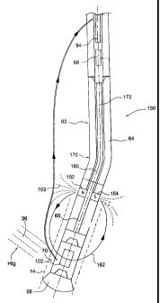
is
illustrated in FIGs. 16 and 17, for example.
[0061] One embodiment of the invention is illustrated diagrammatically at
150
in FIG. 6, wherein components similar to the illustrations of FIGs. 1-3 are
similarly
numbered. In this figure, only the borehole bottom portion of the drilling
assembly of
FIG. 3 is illustrated for convenience. In the illustrated embodiment, an
auxiliary
dipole electromagnet 152 is fastened to the drilling assembly, for example to
the
bottom, or distal end 154, of the bent housing 64 of the drilling motor 62.
The
electromagnet is mounted to be perpendicular to the longitudinal axis 160 of
the
lower portion of the bent housing and of the drill head 68 so as to produce an
auxiliary alternating electromagnetic field 162 having its axis 163 also
perpendicular
to axis 160 and thus perpendicular to the axis of the relief borehole 14 being
drilled
when the bent housing is in the "sliding" mode. As illustrated, the dipole
source is
located below the bend, or elbow 170 in the bent housing 64, so that axis 160
is the
axis of the lower portion of the housing. As is known, the bent sub or housing
64
incorporates a constant velocity joint in the motor to enable fluid flow
through the
motor to drive the drill head.
[0062] The direction of the field lines of the field 162 generated by the
auxiliary
field source magnet 152 is measured by the electromagnetic field sensors 103,
104
and 105 in the instrument package 102 (FIG. 4) that is carried by the drill
bit sub 70
to determine the angular orientation of the lower part of the drill housing
with respect
to the measured target field. Simultaneous measurements of this auxiliary
field and
of the target electromagnetic field then make it possible to determine the
direction to
the blowout with reference to the drilling assembly without using an
intermediate
parameter such as, for example, the direction of gravity when the drill
assembly is
near the vertical. Since the rotational, or angular orientation of the motor
housing 64
controls the direction of the drilling direction, comparing the direction of
the auxiliary
field 162 produced by electromagnet 152 with that of the target field 36
generated by
current flow in the target well 12 makes it possible optimally to rotationally
orient the
drilling assembly to achieve the corrective action desired. This principle can
be used
whether the corrective drilling direction is controlled by the orientation of
a bent
19
WO 2012/009375 CA 02805197 2013-01-11PCT/US2011/043741
motor housing or, in the case of rotary steerable drilling, the bending of the
drill string
itself. In the latter case the electromagnet 152 would be mounted on the
mechanism
controlling the drill stem bend. Although the application of the present
invention to
bent motor housing drilling is illustrated herein, applying the same
principles to rotary
steerable drilling thus will be apparent to those skilled in the art.
[0063] As illustrated in FIGs. 6 and 7, the electromagnet 152 adds the
auxiliary alternating dipole magnetic field 162 (Hdp) to the target
electromagnetic
field Htg (field 36 in FIG. 1) produced by the target current flow at the
drill bit sub 70
at the lower end of the drilling motor 62. As described above, the drill bit
sub carries
the drill bit instrument 102 (FIG. 4), where AC magnetic field sensors 103,
104 and
105 measure the components Hx1, Hy1, Hx2, Hy2, Hz1 and Hz2, respectively, of
the
electromagnetic fields at that location. The first four measurements are the
important
components for the present consideration. Thus, these sensors respond to the
AC
magnetic fields in their vicinity, i.e., the target fields generated by the
target well 12
at a first frequency, and the auxiliary fields generated at a second frequency
by the
dipole source 152 at the lower end of the drill motor, the different
frequencies
allowing the field measurements to be distinguished from each other. FIG. 6
shows
the electromagnet 152 as having N and S poles to depict the direction of the
dipole
field axis 163; however, it will be understood that the illustrated NS pole
orientation is
an instantaneous value, the N and S poles alternating because of the
alternating
current powering the dipole source 152.
[0064] To consider the physical principles of the method and apparatus of
this
invention, reference is made to FIG. 7, which illustrates a view looking down
the
relief well axis 160 in the vicinity of the target borehole 12. Since the bend
170 in the
motor is just a few degrees, any difference in the electromagnetic field
directions with
respect to the relief well axis shown at 172 in FIG. 6 and the instantaneous
drilling
axis 160 of the drill 68 can be neglected. As Illustrated in FIG. 7, ARtgHtg
is the
angle between the projection Rtg of the radius vector R to the target 12 on
this view
and the projection Htg of field 36 generated by target currents, and is 90
degrees.
The projection of field 162 (Hdp) generated by the dipole source 152 is also
shown in
FIG. 7. Since the dipole source 152 is fixed to the lower end of the bent
housing in
one embodiment of the invention, or is located in a separate sub above, and
having
a known angular relationship to, the motor sub in another embodiment, the
angular
20
WO 2012/009375 CA 02805197 2013-01-11PCT/US2011/043741
direction Bd of the drill stem bend 170 with respect to the dipole source 152
is
known, and accordingly the direction of the sensors 102 is also known. The
relative
direction of the sensors is represented by vector 174 in FIG. 7, and the angle
ABdHdp is known by mechanical construction parameters. The directions of both
auxiliary field 162 (Hdp) and target field 36 (HTg) can be measured using the
same
electromagnetic field sensors 102, as noted above. As illustrated in FIG. 7,
the angle
ABdRtg between the direction 174 of the drill motor bend and the direction Rtg
to the
target 12 is given by:
ABdRtg = ABdHdp +AHdpHtg + pi/2 (Eq. 1)
Thus, the direction of drilling direction correction to be made, ABdRtg, to
cause the
drill to intersect the target well 12 is determined directly from the
measurements of
the target field, the auxiliary field and the known angle between the axis of
the
auxiliary field source and the actual direction of the bent drill housing,
without the
need for additional orientation measurements such as the direction of the
Earth's
field or Gravity.
[0065] The field source 152 in FIG. 6 is shown as being on the lower part of
the drilling motor bent sub 64, below the "tool face" bend 170 in the housing
so that
its axis is perpendicular to the tool face; i.e., to the face of the drill bit
64. Since the
bend 170 is typically small, the axis 163 of the field source is not only
perpendicular
to the bent housing axis 160, but may be considered to be substantially
perpendicular to the direction of drilling represented by axis 172. The angle
ABdHdp
between the direction (Bd) of bend 170, represented by vector 174, that
produces
the direction of drilling by the motor, and the direction 162 of the dipole
152 and its
field Hdp is arbitrary, but must be known.
[0066] The configuration of FIG. 6 shows the electromagnetic dipole source
152 as being very close to the drill bit sensors 102, and this minimizes the
battery
power needed to energize the dipole field source. The target-generated
magnetic
field 36 (Htg) and the dipole source field 162 (Hdp) have different
frequencies of
excitation, in accordance with the invention, so that the signal averaging
electronics
in the computer 108 in the drill bit instrumentation sub 102 is capable of
separating
21
WO 2012/009375 CA 02805197 2013-01-11PCT/US2011/043741
the two signals. To do this requires readily available software embedded in
the
computer 108 in drill bit instrument sub 102.
[0067] Measurement of the target electromagnetic field 36 (Htg) gives the
azimuthal angle ARtgHtg of the direction to the target well from the drill bit
instrument sensors 102, which is 90 degrees, while measurement of the
direction of
the auxiliary magnetic field 162 (Hdp) from the drilling motor gives the
relative
azimuthal angle AHdpHtg of the vector of field 162 (Hdp) with respect to the
target
well field 36 The orientation 174 of the sensors and thus of the drill bit
instrument sub
is indicated by angle ABdHdp, and is known from the mechanical construction of
the
auxiliary source. As shown above, the sum of these angles gives the azimuthal
angle
(ABdRtg) between the direction 174 of the tool face (i.e., the face of the
drill bit 68)
and the direction of source 12 of the target field Htg, and thus provides the
relative
orientation of the bent housing of the motor, which controls the direction of
drilling,
and the drill bit sub, this difference being the change of direction required
to adjust
the drilling direction.
[0068] To demonstrate the efficacy of the apparatus shown in FIG. 6 in
carrying out the method of the present invention, a test apparatus,
illustrated in FIGs.
8 and 9, was assembled. It consisted of the drill bit instrument sub 70
described
above as incorporating the instrument package 102 illustrated in FIG. 4. A
short
length of 5 inch diameter steel pipe 180 was used to simulate the presence of
the
steel at the lower end 154 of drilling motor bent housing 64. The auxiliary
electromagnetic field source 152 consisted of two thin mu metal strips 182 and
184,
each of which was 3/8" wide, wrapped around opposite sides of the pipe 180.
The
strips 182 and 184 were each constructed with outwardly facing flanges on each
end, upper and lower flanges 186 and 188 on strip 182 to form outwardly facing
cavities 190 and 192, and flanges 194 and 196 on strip 184, to form outwardly
facing
cavities 198 and 200. The upper and lower cavities were secured back-to-back,
on
opposite sides of the steel pipe, to form pole pieces for the electromagnetic
source
152 and to provide bobbins for receiving upper and lower coils 202 and 204.
The
axis 206 of the source 152 is perpendicular to the axis 160 of the simulated
drill
motor housing 180. In an actual application the pole pieces would be flush
with the
drilling motor housing.
22
WO 2012/009375 CA 02805197 2013-01-11PCT/US2011/043741
[0069] The coils 202 and 204 each had about 10,000 turns of #40 wire and
were connected via leads 208 and 210, respectively, to a strongly attenuated
output
from a power supply 212 of the type normally used to excite electrode current
for
relief well work. About 600 micro amperes of current at about 3 volts at a
frequency
of 15 Hertz powered the coils. The x and y components of the resulting field
162
were measured at the sub 70 by the x and y magnetometers 103 and 104, which
produced corresponding output signals Hx1, Hx2, and Hy1, Hy2 as the instrument
was rolled about its axis. These outputs are illustrated by the measurement
points
indicated at 220 and 222 in FIGs. 10 and 11, respectively. The magnetometers
103
and 104, and thus the Hx and Hy signals 220 and 222, are in quadrature with
each
other and the signals had a large amplitude, about 100 times the background
fluctuations. When this electromagnetic source 152 is mounted on a drilling
motor
bent sub 64, the rotational angle between the drill sub 70 and the magnetic
axis of
the source on the lower part of the drilling motor housing can be found from
these
data through the use of the 4 quadrant arc tangent function, i.e., the angle
given by
the relation atan2 ((Hy1+Hy2), (Hx1+Hx2)).
[0070] An alternative apparatus is illustrated in FIGs. 12-14, wherein a
suitable electromagnetic magnetic dipole source 230 consisting of coils 232
and 234
is mounted on a drill string sub 236. This sub 236 is independent of the bent
housing
of the drilling motor, and may be incorporated in the drill string 50 at a
suitable
location above (uphole of) the bent sub 64. As illustrated in FIG. 15, the
coils 232
and 234 in sub 236 are connected to the AC source 212 via leads 238 and 240.
Tests indicated that 3 amperes of current from the source to the coils is
sufficient to
give a signal of acceptable strength at the sensor instrument package 102 in
sub 70
at a distance of 35 feet away. This is a representative configuration with
this dipole
source sub 236 mounted directly above the drilling motor. The power required
can
be supplied by a battery of modest size. The use of such an electromagnetic
source
in an independent sub, instead of being mounted on the bent housing of the
drilling
motor, increases its versatility, making it useful in both a wire line system
and as a
part of an MWD version of the invention, to be described below.
[0071] As discussed above, in one form of the invention the electromagnetic
field detection system is incorporated in a drill string having a receiver
instrument
package 94 carried by a wireline 90 (FIG. 3). In accordance with another
23
WO 2012/009375 CA 02805197 2013-01-11PCT/US2011/043741
embodiment of the present invention, the independent sub 236 discussed with
respect to FIGs. 1 2-1 5 may be the nonmagnetic sub 84 of such a drill string,
illustrated in this case at 250 in FIG. 16, where the auxiliary
electromagnetic field
source 230, including coils 232 and 234, is incorporated as a part of the
receiver
package 94, as indicated at 252. When the receiver 252 is lowered into the
drill
string for field measurement, it is dropped into an orienting key 254 so that
its
relationship to the drill string will be known. The "stand alone" source 230
is
connected via the wireline to the surface so that it can be controlled
remotely by the
wire line apparatus. Aside from controlling the stand alone field source, the
system
operates as disclosed above with respect to FIG. 3.
[0072] In still another embodiment, the auxiliary source carried by the
receiver
94 can be a solenoid, in which case the source must be somewhat stronger but
can
be powered from an AC source at the surface using a wire line conductor from
the
surface. In this case the wire line instrument still performs the other
functions
discussed above; i.e., it still provides excitation for the drill string
electrode which
emits formation current for the target well and transmits the data received
from the
drill bit instrument to the surface. In this embodiment, an electromagnetic
source with
a dipole axis perpendicular to the drill string axis is mounted at the distal
end of the
receiver tool 94 which sets into the orienting plate 254 in the drill string
above the
MWD 88.
[0073] Another embodiment of the invention is illustrated at 270 in FIG. 17,
wherein an auxiliary magnetic field source 272, which is a dipole magnetic
source
such as a solenoid with its axis perpendicular to the drill string, is part of
a totally
integrated MWD system 274. In this case, the entire MWD package 274 is battery
powered, with the conventional MWD electronics doing the normal drilling
functions
of determining the current borehole direction and inclination. This MWD
package 274
also incorporates the receiver equipment of the receiver package 94 as well as
electromagnetic target location determining functions. In this case the MWD
274
controls the drill bit instrument, the electrode power for delivering current
to the
target well, and energizes the auxiliary electromagnetic dipole source for
determining
the drill bit instrument orientation.
[0074] Although the present invention has been described in terms of
preferred embodiments, it will be understood that numerous modifications and
24
WO 2012/009375 CA 02805197 2013-01-11PCT/US2011/043741
variations may be made without departing from the true spirit and scope
thereof, as
defined in the following claims.
25