Note: Descriptions are shown in the official language in which they were submitted.
CA 02805336 2013-01-14
WO 2012/007808 PCT/1B2011/001471
ENERGY EFFICIENT PRODUCTION OF CO2 USING SINGLE STAGE
EXPANSION AND PUMPS FOR ELEVATED EVAPORATION
Specification
The invention relates to a method and a device for the
liquefaction of the CO2 contained in the flue gases. The
liquefaction of CO2 out of flue gases has been known for
quite a long time.
Most cryogenic methods for the production of CO2 out of
combustion flue gases use conventional separation schemes
having two or more separation stages. In figure 1 such a
prior art installation is shown as block diagram.
In the figures of this application the temperature and the
pressure at various points of the flue gas stream as well as
of the CO2 are indicated by so-called flags. The
temperatures and the pressures belonging =to each flag are
compiled in a chart in the following. It is obvious for a
man skilled in the art that these temperatures and pressures
are meant as an example. They can vary depending on the
composition of the flue gas, the ambient temperature and the
requested purity of the liquid CO2.
In a first compressor 1 the flue gas is compressed. This
compression can be a multi-stage compression process with
coolers and water separators between each compression stage
(not shown) separating most of the water vapour resp. water
from the flue gas.
In figure 1 the flue gas stream is designated with reference
numeral 3. When being emitted by the first compressor 1 the
flue gas has a temperature significantly higher than the
ambient temperature and then is cooled to approximately 13 C
by a first cooler 5. The pressure is approximately 35.7 bar.
The moisture still contained in the flue gas stream 3 is
freed from water by a suitable drying process e.g.
adsorption dried in a drier 7 and subsequently conveyed to a
first separation stage 9. This first separation stage 9
1
CONFIRMATION COPY
CA 02805336 2013-01-14
WO 2012/007808 PCT/1B2011/001471
comprises a first heat exchanger 11 and an intermediate
separation drum 13. The first heat exchanger 11 serves for
cooling the flue gas stream 3. As a result of this cooling a
partial condensation of the CO2 contained in the flue gas
stream 3 takes place. Consequently, the flue gas stream 3
enters the intermediate separation drum 13 as a two-phase
mixture. There the liquid phase and the gaseous phase of the
flue gas stream are separated by means of gravitation. In
the first separation drum the pressure is approximately 34,7
bar and the temperature is -19 C (cf. flag no. 5).
At the bottom of the intermediate separation drum 13 liquid
CO2 is extracted and via a first pressure reducing valve
15.1 expanded to a pressure of approximately 18.4 bar (cf.
ref. No. 3.1). This results in a temperature of the CO2
between -22 C and -29 C (cf. flag no. 10). The partial CO2
stream 3.1 of the flue gas is heated and evaporated in the
first heat exchanger 11 by the flue gas stream 3. At the
exit of the first heat exchanger 11 the partial stream 3.1
has a temperature of approximately 25 C and a pressure of
approximately 18 bar (cf. flag no. 11).
Following the second partial stream 3.2 being extracted at
the head of the intermediate separation drum 13 it becomes
clear that this partial stream 3.2 being extracted from the
intermediate separation drum 13 in a gaseous state is cooled
in a second heat exchanger 17 and partially condensed.
Afterwards this partial stream 3.2 being also present as
two-phase mixture is conveyed to a second separation drum
19. The second heat exchanger 17 and the second separation
drum 19 are the main components of the second separation
stage 21.
In the second separation drum 19 again a gravity-supported
separation between the liquid phase and the gaseous phase of
the partial stream 3.2 takes place. In the second separation
drum 19 there is a pressure of approximately 34,3 bar and a
temperature of approximately -50 C (cf. flag no. 6).
The gaseous phase in the second separation drum 19, the so-
called offgas 23, is extracted at the head of the second
2
CA 02805336 2013-01-14
WO 2012/007808 PCT/1B2011/001471
separation drum 19, expanded to approximately 27 bar in a
second pressure reducing valve 15.2, so that it cools down
to approximately -54 C (cf. flag no. 7).
In the figures the offgas is designated with reference
numeral 23. The offgas 23 streams through the second heat
exchanger 17 thereby cooling the flue gas 3.2 in the counter
stream.
At the bottom of the second separation drum 19 liquid CO2
(c. f. ref. num. 3.3) is extracted and expanded to
approximately 17 bar in a third pressure reducing valve
15.3, so that it reaches a temperature of -54 C as well (cf.
flag no. 7a). This stream 3.3 as well is conveyed to the
second heat exchanger 17. In the second heat exchanger 17 a
part of the liquid CO2 evaporates and stream 3.3 is expanded
to approximately 5 to 10 bar in a fourth pressure reducing
valve 15.4, so that at this point a temperature of -54 C is
reached (cf. flag no. 7b) and the stream 3.3 is again
conveyed to the second heat exchanger 17.
After the stream 3.3 streamed through the second heat
exchanger 17, it again is conveyed to the first heat
exchanger 11. At the entrance of the first heat exchanger 11
this stream has a pressure of approximately 5 to 10 bar with
a temperature of -22 to -29 C (cf. flag no. 14).
This stream 3.3 takes up heat in the first heat exchanger
11, so that at the exit of same it has a temperature of
approximately -7 C with a pressure of approximately 5 to 10
bar. The third stream 3.3 is conveyed to a second compressor
25 at the first compressor stage, whereas the stream 3.1
having a pressure of approximately 18 bar is conveyed to the
second compressor stage at the three-stage compressor 25
shown in figure 1.
Intercooler between the various stages of the second
compressor 25 and an aftercooler for the compressed CO2 are
not shown in figure 1.
At the exit of the second compressor 25 the compressed CO2
has a pressure of between 60 bar and 110 bar with
3
CA 02805336 2013-01-14
WO 2012/007808 PCT/1B2011/001471
temperatures of 80 C to 130 C. In the aftercooler, which is
not shown, the CO2 is cooled down to ambient temperature.
If necessary the CO2 can be either fed directly into the
pipeline or liquefied and conveyed from a first CO2 pump 27
e.g. into a pipeline (not shown). The first CO2 pump 27
raises the pressure of the liquid CO2 to the pressure given
in the pipeline.
Going back to the offgas 23 it can be seen that the offgas
streams through the second heat exchanger 17 and the first
heat exchanger 11, thereby taking up heat from the flue gas
stream 3. At the exit of the first heat exchanger 11 the
offgas 23 has a temperature of approximately 26 C to 30 C
and a pressure of approximately 26 bars (cf. flag no. 16).
For maximising the energy recovery it is known to overheat
the offgas 23 with an offgas superheater 29 and then convey
it to a expansion turbine 31 or any other expansion machine.
Wherein mechanical energy is recycled and afterwards the
offgas is emitted into the surroundings with a low pressure
approximately corresponding to the surrounding pressure.
This installation described by means of figure 1 for
liquefying CO2 is relatively simple and works without
problems. The disadvantage of this prior art production of
liquid CO2 out of flue gas of power plants e.g. fuelled with
fossils is its high energy demand having negative effects on
the net efficiency degree of the power plant.
Thus the invention has the object to provide a method and an
installation for liquefying the CO2 contained in the flue
gas operating with a reduced energy demand and thus
increasing the net efficiency degree of the power plant.
At the same time the method should be as simple as possible
and the operation technique favourably controllable in order
to guarantee a robust and trouble-free operation.
According to the invention this object is solved with a
method for producing liquid CO2 out of combustion flue gases
wherein the flue gas is partially condensed in a single
stage phase separation, the single stage phase separation
4
CA 02805336 2014-07-04
78396-219
separated after having passed the at least one heat exchanger into liquid CO2
and gaseous CO2
in an additional separation drum, wherein the gaseous CO2 and the liquid CO2
of the
additional separation drum are expanded to a second pressure level. A second
part of the
liquid CO2 of the separation drum is expanded to a third pressure level for
cooling the CO2 in
the at least one heat exchanger.
Some embodiments of the invention relate to a method for producing liquid CO2
from
combustion flue gases partially condensed in a single stage phase separation,
comprising:
cooling the combustion flue gases in at least one heat exchanger; separating
the combustion
flue gases in offgas and liquid CO2 in a separation drum, expanding the offgas
and forwarding
the expanded offgas to the at least one heat exchanger for cooling the
combustion flue gas,
expanding a first part of the liquid CO2 from the separation drum and
forwarding the
expanded first part of the liquid CO2 to the at least one heat exchanger for
cooling the
combustion flue gas, separating the expanded first part of the liquid CO2 into
liquid CO2 and
gaseous CO2 after having passed the at least one heat exchanger into an
additional separation
drum; expanding the gaseous CO2 and the liquid CO2 of the additional
separation drum to a
first pressure level and forwarding the expanded gaseous CO2 and liquid CO2 to
the at least
one heat exchanger for cooling the combustion flue gas; expanding a second
part of the liquid
CO2 from the separation drum to a second pressure level and forwarding the
expanded second
part of the liquid CO2 to the at least one heat exchanger for cooling the
combustion flue gas.
Some embodiments of the invention relate to a plant for producing liquid CO2
from partially
condensed combustion flue gases comprising: at least one heat exchanger for
cooling the
combustion flue gases; a separation drum for separating the combustion flue
gases cooled at
the at least one heat exchanger in offgas and liquid CO2; a valve for
expanding the offgas and
a line for forwarding the expanded offgas to the at least one heat exchanger
for cooling the
combustion flue gas, a valve for expanding a first part of the liquid CO2 from
the separation
drum and a line for forwarding the expanded first part of the liquid CO2 to
the at least one heat
exchanger for cooling the combustion flue gas, an additional separation drum
for separating
the expanded first part of the liquid CO2 into liquid CO2 and gaseous CO2
after having passed
the at least one heat exchanger; valves for expanding the gaseous CO2 and the
liquid CO2 of
the additional separation drum to a first pressure level and lines for
forwarding the expanded
5
CA 02805336 2014-07-04
78396-219
gaseous CO2 and liquid CO2 to the at least one heat exchanger for cooling the
combustion flue
gas; a valve for expanding a second part of the liquid CO2 from the separation
drum to a
second pressure level and a line for forwarding the expanded second part of
the liquid CO2 to
the at least one heat exchanger for cooling the the combustion flue gas, a
second multi-stage
compressor.
Due to the reduced volume flow resulting from evaporation of the CO2 at a
higher pressure
level the result may be a considerable reduction of the required power for the
second
compressor 25 having the direct effect of an improved net efficiency degree of
the upstream
power plant.
A further advantageous embodiment of the claimed invention comprises the step
that the
pressure of a third part of the liquid CO2 of the first separation drum is
raised to a fourth
pressure level for cooling the CO2 in the at least one heat exchanger.
This CO2 stream then can be fed to the compressor 25 at an even higher
compression stage
resulting in a further reduced power consumption.
It is preferred that the second part of the liquid CO2 of this separation drum
is expanded to a
pressure of approximately 15 bar to 25 bar, preferably to 20 bar. This
pressure range matches
with the common compression ratios usually applied for centrifugal
compressors.
A further advantageous embodiment of the claimed method comprises that the
third part of
the liquid CO2 of the first separation drum is raised to a pressure of
approximately 40 bar to
50 bar, preferably to 45 bar.
These pressure levels allow an energy efficient operation of the plant on the
one hand while
keeping commercially available compression ratios and allow to run the plant
at
5a
CA 02805336 2013-01-14
WO 2012/007808 PCT/1B2011/001471
different operating points depending for example on the
required quality of CO2 and/or ambient temperature.
It is also advantageous to use the partial streams of CO2
from the separation drums for cooling purposes in the at
least one heat exchanger.
By using these CO2 streams for cooling purposes it can be
avoided to use flammable cooling media, which results in a
reduced danger of fire and minimizes the costs for security
systems.
By feeding the CO2 streams to different stages of a second
compressor depending on their pressure level a reduction of
the energy consumption is achieved.
Compressing the flue gas (3) in a first compressor and then
cooling it in a first cooler and/or drying it in a drier
before entering the at least one heat exchanger reduces the
volume of the flue gas, since most of the water vapour has
been separated. This means that the size of the drier and
the plant for producing liquid 002 can be smaller resulting
in reduced energy losses and reduced costs.
By expanding the offgas from the last separation stage to
approximately 27 bar and resulting in a temperature of
approximately -54 C before entering the at least one heat
exchanger the pressure level after expansion is as high as
possible thus maximizing the energy recovery in the
expander.
A further reduction of the energy consumption can be
achieved by expanding the offgas after having passed the at
least heat exchanger in at least one expansion machine and
subsequently feeding it again to the at least one heat
exchanger.
Optionally the offgas 23 can be superheated after having
passed the at least heat exchanger and before entering the
at least one expansion machine. If waste heat can be used
for superheating, the output of the expansion machine can be
increased resulting in an better overall efficiency of the
plant.
6
CA 02805336 2013-01-14
WO 2012/007808 PCT/1B2011/001471
Preferably two expansion stages are to be used (c. f. fig.
3) thus maximizing the amount of CO2 that can be directed to
the third and fourth pressure level.
Further advantages of the claimed invention are explained in
connection with figures 2 and 3 in the following.
Drawings
Shown are in:
Figure 1 an installation for CO2 liquefaction out of flue
gases according to the prior art and
Figures 2 and 3 embodiments of installations for CO2
liquefaction according to the invention.
Description of the Drawings
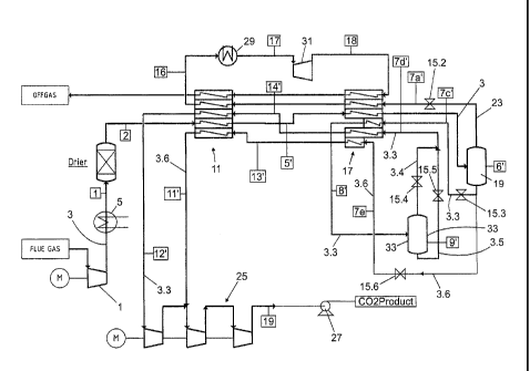
In figure 2 identical components are designated with
identical reference numerals. The statements concerning
figure 1 correspondingly apply.
The treatment of the flue gas stream 3 in the first
compressor 1, the first cooler 5, the drier 7, the first
heat exchanger 11 takes place as described by means of
figure 1. The flue gas stream 3 flows from the first heat
exchanger 11 directly to the second heat exchanger 17 and is
then conveyed to the now first separation drum19. The two
phases (liquid and gaseous) of the flue gas stream 3 are
divided in the first separation drum 19 into the offgas
stream 23 and a partial stream of liquid CO2. At the bottom
of the first separation drum 19 this partial stream is
extracted and has the reference numeral 3.3 such as in
figure 1.
As already explained in the description of figure 1, the
partial stream 3.3 is expanded to a pressure of 17,5 bar in
a third pressure reducing valve 15.3, thereby cooling down
to -54 C. The partial stream 3.3 streams through the second
heat exchanger 17, thereby taking up heat from the flue gas
7
CA 02805336 2013-01-14
WO 2012/007808
PCT/1B2011/001471
stream 3 and enters with a temperature of approximately -
47 C (cf. flag no. 8') into a second separation drum 33.
There the partially liquid and partially gaseous CO2 has a
pressure of approximately 16,5 bar and a temperature of -47
C (cf. flag no. 9').
In the head of the second separation drum 33 the gaseous
phase is extracted and expanded in a fourth pressure
reducing valve 15.4. The gaseous partial stream being
extracted at the head of the second separation drum 33 is
designated with reference numeral 3.4 in figure 2.
At the bottom of the second separation drum 33 a liquid
stream 3.5 is extracted and expanded in a fifth pressure
reducing valve 15.5. Subsequently the partial streams 3.4
and 3.5 are brought together again. Then they have a
pressure of approximately 5 to 10 bar and a temperature of -
54 C (cf. flag no. 7d').
A second portion 3.6 of the CO2 from the first separation
drum 19 is expanded via a sixth pressure reducing valve 15.6
to a pressure of 23
bar (c. f. flag 7e') and returned to
the exchanger 17 at an intermediate entry point.
With this partially liquid, partially gaseous CO2 the flue
gas stream 3 in the second heat exchanger 17 is cooled.
As the entrance temperature of the partial stream 3.6 is
higher than the entrance temperatures of the offgas 23 as
well as the partial stream 3.3, the flue das stream 3 first
is cooled with the partial stream 3.6. Thus it is possible
to take up heat from the flue gas stream 3 even with this
higher temperature of -45 C. In figure 2 this fact is
illustrated by the position of the heat exchanging area of
the partial stream 3.6.
The partial stream 3.6 leaves the second heat exchanger 17
with a temperature of approximately -22 C to -29 C (cf. flag
no. 13') and is then conveyed directly the first heat
exchanger 11. In the first heat exchanger 11 the partial
stream 3.6 takes up heat from the flue gas stream 3. The
partial stream 3.6 leaves the first heat exchanger (cf. flag
8
CA 02805336 2013-01-14
WO 2012/007808 PCT/1B2011/001471
no. 11') with a temperature of approximately 25 C and a
pressure of approximately 18 bar and can thus be conveyed to
the second compression stage of the second compressor 25.
As the partial stream 3.6 can be conveyed to the second
compression stage of the second compressor 25, the partial
stream 3.3, which has to be conveyed to the first
compression stage of the second compressor 25, is
correspondingly reduced. Consequently the power required by
the second compressor 25 is smaller. This has positive
effects on the energy demand of the installation according
to the invention.
Occasionally the remainder 3.7 of the liquid CO2 from the
first separation drum 19 is pumped (c. f. ref. number 37) to
a pressure of===,- 45 bar (c. f. flag 7g) with the CO2 pump 37
and returned to exchanger 17 also at an intermediate entry
point.
Parallel to the partial stream 3.6 a further partial stream
3.7 flows through the second heat exchanger 17 and the first
heat exchanger 11. The partial stream 3.7 is driven by a CO2
pump 37 and brought to an increased pressure level of
approx. 45 bar (cf. flag no. 7g). An eighth valve 15.8
serves to control the amount of CO2 that is pumped by the
Co2 pump 37.
As the entrance temperatures of the partial streams 3.6 and
3.7 are higher than the entrance temperatures of the offgas
23 as well as the partial stream 3.3, the flue gas stream 3
first is cooled with the partial streams 3.6 and 3.7. Thus
it is possible to take up heat from the flue gas stream 3
even with the a. m. higher temperature. In figure 2 this
fact is illustrated by the position of the heat exchanging
area of the partial stream 3.7.
The partial stream 3.7 leaves the second heat exchanger 17
with a temperature of approximately -22 C to -29 C (cf. flag
no. 20) and is then conveyed directly the first heat
exchanger 11. In the first heat exchanger 11 the partial
stream 3.7 takes up heat from the flue gas stream 3. The
partial stream 3.7 leaves the first heat exchanger (cf. flag
9
CA 02805336 2013-01-14
WO 2012/007808 PCT/1B2011/001471
no. 21) with a temperature of approximately 25 C and a
pressure of approximately 44 bar and can thus be conveyed
after the second and before the third compression stage of
the second compressor 25.
As the partial stream 3.7 can be conveyed to the third
compression stage of the second compressor 25, the partial
stream 3.3, which has to be conveyed to the first
compression stage of the second compressor 25, is
correspondingly reduced. Consequently the power required by
the second compressor 25 is smaller. This has positive
effects on the energy demand of the installation according
to the invention.
Extraction of partial stream 3.7 is possible when the off-
gas energy is used by at least double expansion via
expanders 31 and 39 as shown in figure 3. This maximizes the
cold recovery from the off-gas as described later.
All liquid or two phase CO2 streams (3.3, 3.6., 3.7) are
evaporated in exchanger 17 and 11 before being sent to CO2
recompressor or second compressor 25. Depending on the
pressure level the CO2 streams are fed at different
compression stages of the second compressor 25.
Using different pressure levels for the evaporation of the
CO2 has several advantages: It gives better control over the
flue gas condensation. Furthermore the overall compression
requirements can be minimized having CO2 at elevated
pressures readily available.
A further possibility of reducing the energy demand of the
CO2 liquefaction plant can be seen in not only overheating
the offgas 23 in the offgas superheater 19 after the exit
from the first heat exchanger 11, but also reconvey it to
the second heat exchanger 17 after the expansion in the
expansion turbine 31. After the overheating the offgas has a
temperature of approximately 80 C to approximately 100 C
with a pressure of approximately 26 bar (cf. flag no. 17).
By the expansion in the first expansion machine 31 the
pressure drops to 2.3 bar and the offgas 23 reaches a
temperature of -54 C. Thus the offgas 23 can once more
CA 02805336 2013-01-14
WO 2012/007808 PCT/1B2011/001471
contribute to the cooling of the flue gas stream 3 resp. the
partial stream 3.2. Afterwards the offgas 23 can be emitted
to the surroundings with a low pressure and approximately
surrounding temperature.
It is also possible to carry out a multi-stage expansion and
overheating of the offgas 23 as is shown in figure 3.
In the embodiment shown in figure 3 the offgas 23 is but
sent directly after the exit from the first heat exchanger
11 to the first expansion turbine 31 and further to the
second heat exchanger 17. From the second heat exchanger 17
the offgas flows through the first heat exchanger 11. Before
entering the first expansion turbine 31 the offgas has a
temperature of approximately 30 C with a pressure of
approximately 26 bar (cf. flag no. 16). Due to the expansion
in the first expansion machine 31 the pressure drops to 8
bar and the offgas reaches a temperature of -54 C.
The second stage of expansion comprises a second expansion
turbine 39. Before entering the second expansion machine 39
the offgas 23 has temperature of approximately 30 C (cf.
flag 22). Due to the expansion in the second expansion
machine 39 the pressure drops to 2 bar and the offgas
reaches a temperature of -47 C (cf. flag 23).
Thus the offgas 23 can once more contribute to the cooling
of the flue gas stream 3 resp. the partial stream 3.2.
Afterwards the offgas 23 can be emitted to the surroundings
with a low pressure and approximately surrounding
temperature.
The single or multi-stage expansion as well results in a
considerable 'reduction of the energy demand of the
installation according to the invention, as on the one hand
the offgas 23 contributes to a greater amount to the cooling
of the flue gas stream 3 resp. the partial stream 3.2 and
the expansion machine 31 and/or 39 generate mechanical work,
which e. g. can be used for driving the first compressor 1
or the second compressor 25. All in all it can be stated
that the method according to the invention and the
installation for CO2 liquefaction required for carrying out
11
CA 02805336 2013-01-14
WO 2012/007808 PCT/1B2011/001471
the method according to the invention are still relatively
simple in their design in spite of the considerable
advantages.
Furthermore, this setup clearly improves the control over
the flue gas condensation. With adjustment of the flow rate
over the CO2 pump 37 and the valves 15. 6 and 15.3 the
driving force for heat transfer, the Logarithmic Mean
Temperature Difference (LMTD), is varied. In this way the
performance of the separation stage can be adjusted. This is
especially important, when operating at condensation
temperatures near the sublimation and freezing point of CO2.
In order to maximize the described effect, the heat recovery
out of the offgas from separation can be increased by having
the vent gas/offgas 23 recirculated to the cold box after
expansion, at least once before releasing it to the
atmosphere.
Table of flags, pressures and temperatures.
Flag no. Temperature, approx. Pressure, approx.
[ C] [bar]
1 13 35,7
2 13 35
5 -19 34,7
5' -19 34,7
6 -51 34,3
6' -51 34,3
71 -54 C 27
7a -54 17
7a' -54 27
7b -54 5 to 10
7b' -48 44
7c -54 17,5
1 1st das Offgas 23 in Figur 1
12
CA 02805336 2013-01-14
WO 2012/007808
PCT/1B2011/001471
7c' -54 17,5
7d -54 5 to 10
7d' -54 5 to 10
7e -45 2O to 23
7g -47 45
7h -47 44
8 -47 16,5
8' -47 16,5
9 -47 16,5
9' -47 16,5
- 22 to - 29 20,5
11 25 20
11' 26 to 30 19
12 -7 5-10
12' -7 5 to 10
13 -22 to -29 20
14 -22 to -29 5-10
16 26 to 30 26
17 80 to 100 25,8
18 -54 2,3
19 80 to 130 60 to 110
-22 to -29 43,5
21 26 to 30 43
22 26 to 30 7
The tolerances for The tolerances for
the temperatures are the pressures are
5 C 5 bar
13