Note: Descriptions are shown in the official language in which they were submitted.
CA 02805365 2013-02-07
MULTI-PORTION WOUND PROTECTOR
BACKGROUND
Technical Field
[0002] The present disclosure relates generally to surgical apparatuses
for use in
minimally invasive surgical procedures, such as endoscopic and/or laparoscopic
procedures, and
more particularly, relates to a surgical apparatus that allows human hands or
multiple surgical
instruments to be inserted through a single opening through body tissue.
Description of Related Art
[0003] Today, many surgical procedures are performed through small
incisions in the
skin, as compared to large incisions that are typically required in
traditional procedures, in an
effort to reduce trauma to the patient and reduce the patient's recovery time.
Generally, such
procedures are referred to as "endoscopic", unless performed on the patient's
abdomen, in which
case the procedure is referred to as "laparoscopic." Throughout the present
disclosure, the term
"minimally invasive" should be understood to encompass both endoscopic and
laparoscopic
procedures.
[0004] During a typical minimally invasive procedure, surgical
instruments, such as
endoscopes, graspers, staplers and forceps, are inserted into the patient's
body through the
incision in tissue. In general, prior to the introduction of the surgical
object into the patient's
body. insufflation gas is supplied to the target surgical site to enlarge its
surrounding area and
CA 02805365 2013-02-07
create a larger, more accessible work area. This is accomplished with a
substantially fluid-tight
seal that maintains the insufflation gas at a pressure sufficient to inflate
the target surgical site.
[0005] In certain minimally invasive procedures, when a certain size of a
specimen needs
to be removed from the patient's body, a relatively large incision needs to be
made. Some
surgeons use the relatively large incision to have their hands in the
operative field to aid the
removal or other surgical procedures. This hand-assist technique reduces
operative time
significantly versus the typical minimally invasive approach, and also gives
the surgeons more
options in dealing with unexpected adverse events, such as uncontrolled
bleeding. While a
surgeon may place his/her hand in the operative field at some time during the
procedure. the
surgeon still needs to work with surgical instruments at other time during the
same procedure,
insufflation gas therefore must be continuously maintained at the target
surgical site throughout
the entire procedure.
[0006] It is desirable to have an access device to accommodate human
hands and surgical
instruments of different dimensions and form a substantial sealing
relationship thereto to inhibit
the escape of insufflation gas. It is also desirable for the access device to
have an opening with
an expandable nature to easily conform with the dimensions of human hands and
surgical
instruments inserted therein.
[0007] The existing access devices in the prior art such as wound
retractors are generally
known for permitting hand-assist procedures, but are also known for their
drawbacks such as
failure to inhibit escape of insufflation gas when instruments of dimensions
smaller than the
hands are operated therethrough.
[0008] Based on the above, a continuing need exists for an access device
with increased
versatility and enhanced sealing features to accommodate human hands and
surgical instruments.
CA 02805365 2013-02-07
SUMMARY
100091 Disclosed herein is a surgical apparatus for positioning within a
tissue tract
accessing an underlying body cavity. The surgical apparatus includes a
flexible member having
an open proximal end, a closed distal end and a passage extending
therebetween. The surgical
apparatus further includes a string extending through the passage of the
flexible member with a
first end extending proximally beyond the open proximal end and a second end
attached to the
closed distal end and.
[00101 In one embodiment, the surgical apparatus includes an anchor member
attached to
the open proximal end of the flexible member. The anchor member is made from a
material
more rigid than that of the flexible material. For instance, the anchor member
is made from a
rigid or semi rigid material. The anchor member defines a passage for
reception of objects
therethrough. The passage of the anchor member is also configured to receive
an access device
therein.
[00111 In some embodiments, the closed distal end of the flexible member
exhibits a
generally conical shape.
[00121 In certain embodiments, an application of force on the string in a
proximal
direction causes the flexible member to invert and propagate in the proximal
direction, and
expose the closed distal end of the flexible member proximally beyond the
anchor member.
[0013] Also disclosed is a method of accessing an underlying body cavity
through a
tissue tract. The method includes positioning a surgical apparatus within the
tissue tract. The
surgical apparatus includes a flexible member defining an open proximal end, a
closed distal end,
and a passage extending therebetween. The surgical apparatus also includes a
string extending
-3-
CA 02805365 2013-02-07
through the passage of the flexible member with a first end extending
proximally beyond the
open proximal end and a second end attached to the closed distal end.
100141 The method also includes pulling the string in a proximal direction
to invert the
flexible member. Additionally, the method includes removing a portion of the
closed distal end
of the flexible member resulting in an opening to permit objects therethrough.
100151 Further, the surgical apparatus includes an anchor member attached
to the open
proximal end of the flexible member. In some embodiments, the method includes
inserting an
access device into a passage defined in the anchor member.
DESCRIPTION OF THE DRAWINGS
[0016] The above and other aspects, features, and advantages of the
present disclosure
will become more apparent in light of the following detailed description when
taken in
conjunction with the accompanying drawings in which:
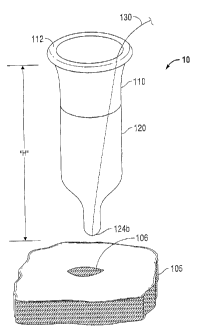
[0017] FIG. 1 is a front perspective view of a surgical apparatus in
accordance with the
principles of the present disclosure illustrating a surgical apparatus
positioned relative to the
tissue;
100181 FIG. 2 is an exploded view of the surgical apparatus of FIG. 1
illustrating an
anchor member and a flexible member;
[0019] FIG. 3 is a side cross-sectional view of the surgical apparatus of
FIG. l
illustrating the surgical apparatus positioned above the tissue;
[0020] FIG. 4 is a side cross-sectional view of the surgical apparatus of
FIG. 3
illustrating the surgical apparatus disposed within the tissue:
-4-
CA 02805365 2013-02-07
[0021] FIG. 5 is a side cross-sectional view of the surgical apparatus of
FIG. 4
illustrating removing a portion of the flexible member of the surgical
apparatus while the flexible
member is inverted;
[0022] FIG. 6 is a side cross-sectional view of the surgical apparatus of
FIG. 5
illustrating the remaining portion of the flexible member disposed within the
tissue;
[0023] FIG. 7 is a side cross-sectional view of the surgical apparatus of
FIG. 6
illustrating an access device positioned above the surgical apparatus; and
[0024] FIG. 8 is a side cross-sectional view of the surgical apparatus of
FIG. 7
illustrating the access device disposed within the surgical apparatus.
DETAILED DESCRIPTION
[0025] Particular embodiments of the present disclosure will be described
herein with
reference to the accompanying drawings. As shown in the drawings and as
described throughout
the following description, and as is traditional when referring to relative
positioning on an object,
the term "proximal" or "trailing" refers to the end of the apparatus that is
closer to the user and the
term "distal" or "leading" refers to the end of the apparatus that is farther
from the user. In the
following description, well-known functions or constructions are not described
in detail to avoid
obscuring the present disclosure in unnecessary detail.
[0026] One type of minimal invasive surgery described herein employs a
device that
facilitates multiple instrument access through a single incision. This is a
minimally invasive
surgical procedure, which permits a user to operate through a single entry
point, typically the
patient's navel. Additionally, the presently disclosed device may be used in a
procedure where a
naturally occurring orifice (e.g. vagina or anus) is the point of entry to the
surgical site. The
disclosed procedure involves insufflating the body cavity and positioning a
portal member
-5-
CA 02805365 2013-02-07
within, e.g., the navel of the patient. Instruments including an endoscope and
additional
instruments such as graspers, staplers, forceps or the like may be introduced
within a portal
member to carry out the surgical procedure. An example of such a surgical
portal is disclosed in
U.S. patent application Serial No. 12/244,024, Pub. No. US 2009/0093752 Al,
filed October 2,
2008, the entire contents of which are hereby incorporated by reference
herein.
[0027] Referring now to the drawings, in which like reference numerals
identify identical or
substantially similar parts throughout the several views, FIG. 1 illustrates a
surgical apparatus 10 in
accordance with the principles of the present disclosure. The surgical
apparatus 10 is adapted for
insertion in a tissue opening 106 within a tissue tract 105. e.g., through the
abdominal or
peritoneal lining in connection with a laparoscopic surgical procedure. The
surgical apparatus 10
will be described in greater detail hereinbelow.
[0028] As shown in FIG. 1, the surgical apparatus 10 may define a
generally cylindrical
shape with a closed distal end. However, it is contemplated that the surgical
apparatus 10 may
define other configurations both prior and subsequent to insertion within the
tissue tract 105.
[0029] With reference to FIG. 2, the surgical apparatus 10 defines a
longitudinal axis
"L", and includes an anchor member (or a proximal member) 110 and a flexible
member (or a
distal member) 120 which are axially aligned along the longitudinal axis "L,"
with the anchor
member 110 mounted on top of or mounted proximally with respect to the
flexible member 120.
The anchor member 110 exhibits a generally cylindrical configuration and
includes a proximal
end 112 and a distal end 114. It is envisioned that the anchor member 110 may
exhibit other
configurations. The anchor member 110 defines a longitudinal passage 111
extending from the
proximal end 112 to the distal end 114 and having a diameter "DI" in its
radial dimension. In
one embodiment, the anchor member 110 has a uniform radial dimension (e.g.
"D1") along its
-6-
CA 02805365 2013-02-07
length. It is also contemplated that the anchor member 110 may exhibit a
tapering configuration
with a gradually changing radial dimension between the proximal end 112 and
the distal end 114.
[0030] The proximal end 112 of the anchor member 110 is in the shape of an
annular
flange 112. As seen in FIG. 3, the annular flange 112 includes an inner wall
112a, an outer wall
112b, a proximal surface 112c and a distal surface 112d. As illustrated in
FIG. 2, the inner wall
112a of the annular flange 112 defines an inner diameter identical to the
diameter "Dl" of the
longitudinal passage 111. The annular flange 112 is configured to be disposed
exteriorly outside
of the tissue opening 106. Specifically, as illustrated in FIG. 2, the outer
wall 112b is configured
to have an outer diameter "D2," which is larger than "Dl" and also
significantly greater than the
size of the tissue opening 106. As illustrated in FIG. 4, when the anchor
member 110 is disposed
in the tissue opening 106, the distal surface 112d of the annular flange 112
abuts the upper side
of the tissue tract 105, and the outer wall 112b of the annular flange 112
inhibits the annular
flange 112 from entering the tissue opening 106 and facilitates retraction of
the tissue opening
106. It is envisioned that when the anchor member 110 is disposed in the
tissue opening 106, the
anchor member 110 forms a substantial sealing relation with the tissue tract
105.
[0031] As illustrated in FIG. 2, the anchor member 110 defines an
insertion length "Hl"
which is a distance measured from the distal surface 112d of the annular
flange 112 to the distal
end 114 of the anchor member 110. The insertion length "Hl" represents the
length of the anchor
member 110 that is insertable into the tissue opening 106. The insertion
length "Hl" is also the
minimum length required to anchor the surgical apparatus 10 within any type of
tissue tract 105.
[0032] With continued reference to FIG. 2, the flexible member 120 of the
surgical
apparatus 10 includes a uniform portion (or a proximal portion) 122 and a
narrow portion (or a
distal portion) 124. The uniform portion 122 exhibits a generally cylindrical
shape with a
-7-
CA 02805365 2013-02-07
longitudinal passage 123 defined therein. The longitudinal passage 123 defines
a uniform radial
dimension along its length, and its radial dimension is identical to that of
the longitudinal
passage 11] . The uniform portion 122 defines an insertion length "H2" which
is insertable into
the tissue opening 106. The insertion length "H2" is identical to the entire
longitudinal length of
the uniform portion 122. The insertion length "H2" of the uniform portion 122
equals to or is
greater than the insertion length "Hl" of the anchor member 110.
[0033] The narrow portion 124 of the flexible member 120 defines a
diameter that varies
along the longitudinal axis "L." In one embodiment. the narrow portion 124
defines a diameter
gradually decreasing in a distal direction along the longitudinal axis "L."
[0034] In a certain embodiment, the narrow portion 124 exhibits a
generally conical
configuration, as seen in FIG. 2. The narrow portion 124 has a circular base
124a immediately
connected to the uniform portion 122. The circular base 124a defines a
diameter "Dl"which is
identical to that of the longitudinal passage 123. Further, the narrow portion
124 has an apex end
(or a distal-most end) 124b, which is closed and has an almost negligible
diameter. The diameter
of the narrow portion 124 gradually decreases along the longitudinal axis "L"
from the circular
base 124a, where the diameter is maximized, to the apex end 124b, where the
diameter is
minimized. The narrow portion 124 defines an insertion length "H3" insertable
into the tissue
opening 106. The insertion length "H3" is a distance measured from the
circular base 124a to
the apex end 124b.
[0035] As seen in FIG. 1. the surgical apparatus 10 defines an insertion
length "H" which
is identical to the combined insertion lengths of the anchor member 110 (i.e.,
"H1-), the uniform
portion 122 (i.e.. "H2"), and the narrow portion 124 (i.e., "H3").
-8-
CA 02805365 2013-02-07
[0036] In a certain embodiment, the anchor member 110 is made of a rigid
or semi rigid
material such as plastic or rubber, which is able to establish a sealing
relation with the tissue tract
105. The flexible member 120 may be made from a semi-resilient, disposable,
compressible and
flexible type (e.g. rubber or sponge) material, for example, but not limited
to, a suitable foam, gel
material, or soft rubber having sufficient compliance to form a seal about one
or more surgical
objects, and also establish a sealing relation with the tissue tract 105 and
with the surgical object.
In one embodiment, the foam includes a polyisoprene material. The resilient
nature of the
flexible member 120 provides an easy insertion and removal of the surgical
apparatus 10 through
the tissue 105.
[0037] In some embodiments, the anchor member 110 is made of a material
more rigid
than that of the flexible member 120.
[0038] In one embodiment, the anchor member 110 is an integrated part of
the flexible
member 120. For instance, the anchor member 110 is permanently attached to the
flexible
member 120 by glue, welding or by an overmolding process.
[0039] In another embodiment, the anchor member 110 is detachably
connected to the
flexible member 120.
[0040] The surgical apparatus 10 further includes a string 130. The string
130 is of a
length substantially greater than the insertion length "H" of the surgical
apparatus 10. In a
certain embodiment, the string 130 is an integrated member of the flexible
member 120. For
instance, the string 130 is permanently attached to the flexible member 120 by
glue, welding or
by an overmolding process.
[0041] As seen in FIG. 2, the string 130 has a first end 130a freely
disposed outside of
the surgical apparatus 10. and a second end 130b connected to an inner wall of
the narrow
-9-
CA 02805365 2013-02-07
portion 124. In one embodiment, the second end 130b is disposed interiorly of
the narrow
portion 124 and attached to the apex end 124b. As seen in FIG. 4, a first
force "Fl" acting on the
first end 130a of the string 130 induces a second force "F2" on the apex end
124b of the surgical
apparatus 10. As seen in FIG. 5, the force "F2" causes the apex end 124b to
invert and propagate
in the proximal direction through the longitudinal passage 123 of the flexible
member 120, and
subsequently through the longitudinal passage 1 1 l of the anchor member 110.
Due to the
flexible nature of the flexible member 120, the flexible member 120 is
inverted under the
application of force "F2." Once the flexible member 120 is completely inverted
as illustrated in
FIG. 5, the force "F2" or the force "Fl" which induced the force "F2" is
removed. In its
completely inverted state, the flexible member 120 is folded inwardly into the
anchor member
110 to the extent that the narrow portion 124 is completely exposed above the
tissue tract 105.
As seen in FIG. 5, the interior of the anchor member 110 is completely
overlaid by at least a
portion of the uniform portion 122. When the flexible member 120 is completely
inverted, the
anchor member 110 remains in a sealing relationship with the tissue tract 105,
and the distal
surface 112d of the annular flange 112 remains in an abutting relationship
with the upper side of
the tissue tract 105.
[0042]
With continued references to FIGS. 5-6, once the narrow portion 124 is exposed
above the tissue tract 105, a part 126 of the narrow portion 124 may be
removed to create an
opening 150 in the remaining part 128 of the narrow portion 124. For instance,
a surgeon may
use a scissor to cut off a part 126 of the narrow portion 124 along the axis
"C" as illustrated in
FIG. 5. The opening 150 is of a size that allows a human hand 300 to pass
therethrough. The
size of the opening 150 varies depending on the size of the part 126 removed
from the narrow
portion 124. For instance. the size of the opening 150 may vary from an almost
negligible
-10-
CA 02805365 2013-02-07
diameter, if only the apex end 124b of the narrow portion 124 is removed, to a
maximum
diameter "DI," when the narrow portion 124 in its entirety is removed. The
surgeon selectively
determines the size of the opening 150 to be created based on the size of the
surgeon's hand 300
that needs to pass through the opening 150. It is envisioned that the opening
150 forms a sealing
relationship with the hand 300 passed therethrough to facilitate hand-assisted
procedures. It is
also envisioned that the opening 150 has an expandable nature to sealingly
accommodate hands
or instruments with radial dimensions greater than the size of the opening
150.
[0043] The
surgical apparatus 10 may also be used in conjunction with an intermediate
access device (e.g. a portal member 400 shown in FIGS. 7 and 8) to receive
surgical objects
having radial dimensions smaller than that of a hand. The longitudinal passage
111 of the
surgical apparatus 10 is adapted to receive the portal member 400 such as that
disclosed in U.S.
patent application Serial No. 12/244,024, Pub. No. US 2009/0093752 Al, filed
October 2, 2008.
The portal member 400 defines at least one longitudinal passage 430 between
its proximal end
410 and its distal end 420 for reception of a surgical object 500 therethrough
in a substantially
sealing relationship. It is envisioned that the surgical object 500 has a
radial dimension
substantially smaller than that of a human hand. With reference to FIG. 7, the
portal member 20
defines a relatively large radial dimension "D4" at its proximal end 410 and
defines a relatively
small radial dimension "DS" at its distal end 420. The radial dimension "DS"
of the distal end
420 equals to or is slightly greater than the radial dimension "Dl"of the
longitudinal passage
111 such that the distal end 420 can fit snugly within the longitudinal
passage 111 and forms a
sealing engagement with the longitudinal passage 111. The radial dimension
"D4" of the
proximal end 410 is significantly larger than the radial dimension "Dl"of the
longitudinal
-11-
CA 02805365 2013-02-07
passage 111. Accordingly, the longitudinal passage 111 prevents the entry of
the proximal end
410.
[0044] In operation, the surgeon inserts the surgical apparatus 10, as
illustrated in FIG. 3,
into the tissue opening 106 of the tissue tract 105 with the first end 130a of
the string 130
extending proximally beyond the annular flange 112 of the surgical apparatus.
The surgical
apparatus 10 advances distally into the tissue opening 106 until the distal
surface 112d of the
annular flange 112 abuts the upper side of the tissue tract 105. Second, the
surgeon pulls the
string 130 proximally as indicated in FIGS. 4-5 to expose the narrow portion
124 proximally
beyond the annular flange 112 of the surgical apparatus 10. Third, with
reference to FIGS. 5-6,
the surgeon removes a part 126 of the narrow portion 124 or the entire narrow
portion 124 to
create an opening 150 which enables the surgeon to perform hand-assist
procedures
therethrough. Fourth, when typical minimally invasive procedures involving
surgical
instruments 500 of small radial dimensions are desired, the surgeon may mount
the portal
member 400 into the longitudinal passage 111 of the surgical apparatus 10 for
receiving the
surgical instruments 500.
[0045] In use, the same surgical apparatus 10 facilitates both hand-
assisted procedures as
well as typical minimally invasive procedures. The surgical apparatus 10 can
sealingly engage
human hands and large instruments of various dimensions, as well as sealingly
engage small
surgical instruments via an intermediate access device (e.g. portal member
400). In the first
scenario, the surgeon creates an opening 150 in the surgical apparatus 10 at
real time to
accommodate the surgeon's hand or an instrument of similar dimension. A large
opening can be
created to sealingly engage a large hand or an instrument of a similar
dimension: and on the
other hand, a small opening can be created to sealingly engage a small hand or
an instrument of a
CA 02805365 2013-02-07
similar dimension. In the second scenario, when an instrument of a dimension
relatively smaller
than the surgeon's hand is desired during the procedure, the surgical
apparatus 10 readily
accommodates an intermediate access device (e.g. portal member 400) for
receiving the
relatively small instrument. The intermediate access device 400 is configured
to form a sealing
relation with the surgical apparatus 10. The intermediate access device 400 is
also configured to
sealingly receive instruments of dimensions relatively smaller than that of
human hands. In both
scenarios, the surgical apparatus 10 forms a substantial sealing relationship
with the tissue tract
105, thereby preventing the escape of insufflation gas.
[0046] Further, the narrow portion 124 with its relatively small dimension
provides easy
insertion and removal of the surgical apparatus 10 through the tissue opening
106, thus, reducing
the time required to place and/or displace the surgical apparatus 10 through
the incisions during
surgical operations and reducing tissue trauma.
[0047] While several embodiments of the disclosure have been shown in the
drawings
and/or discussed herein, it is not intended that the disclosure be limited
thereto, as it is intended
that the disclosure be as broad in scope as the art will allow and that the
specification be read
likewise. Therefore, the above description should not be construed as
limiting, but merely as
exemplifications of particular embodiments. Different embodiments of the
disclosure may be
combined with one another based on the particular needs of the patients to
achieve optimal
results of the surgical procedures. Those skilled in the art will envision
other modifications
within the scope and spirit of the claims appended hereto.
-1 3-