Language selection

Search

Patent 2805467 Summary

Third-party information liability

Some of the information on this Web page has been provided by external sources. The Government of Canada is not responsible for the accuracy, reliability or currency of the information supplied by external sources. Users wishing to rely upon this information should consult directly with the source of the information. Content provided by external sources is not subject to official languages, privacy and accessibility requirements.

Claims and Abstract availability

Any discrepancies in the text and image of the Claims and Abstract are due to differing posting times. Text of the Claims and Abstract are posted:

  • At the time the application is open to public inspection;
  • At the time of issue of the patent (grant).
(12) Patent: (11) CA 2805467
(54) English Title: BLADE CLIP
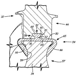
(54) French Title: ATTACHE-LAME
Status: Granted
Bibliographic Data
(51) International Patent Classification (IPC):
  • F01D 5/32 (2006.01)
(72) Inventors :
  • HOU, LIN-JUN (United States of America)
(73) Owners :
  • HAMILTON SUNDSTRAND CORPORATION (United States of America)
(71) Applicants :
  • HAMILTON SUNDSTRAND CORPORATION (United States of America)
(74) Agent: NORTON ROSE FULBRIGHT CANADA LLP/S.E.N.C.R.L., S.R.L.
(74) Associate agent:
(45) Issued: 2015-09-08
(22) Filed Date: 2013-02-08
(41) Open to Public Inspection: 2013-09-06
Examination requested: 2013-02-08
Availability of licence: N/A
(25) Language of filing: English

Patent Cooperation Treaty (PCT): No

(30) Application Priority Data:
Application No. Country/Territory Date
13/412,824 United States of America 2012-03-06

Abstracts

English Abstract

A clip to connect a blade to a rotor disk, the blade with a root and a tip in a spanwise direction, and a leading edge and a trailing edge in a chordwise direction, the root with a bottom surface, includes a locking mechanism shaped to engage a complementary slot extending into the bottom surface of the blade root in the spanwise direction; a support connected to the locking mechanism extending the length of the bottom surface of the root in the chordwise direction; and first and second arms extending radially inward converging in an axial direction so that the arms are closer at their distal ends to engage the rotor disk.


French Abstract

Un collier de serrage pour fixer une pale à un disque rotor, la pale avec une racine et une pointe dans le sens de lenvergure et un bord dattaque et un bord de fuite dans le sens longitudinal du profil, la racine avec une surface inférieure comprend un mécanisme de blocage présentant une forme permettant la mise en prise dans une fente complémentaire sétendant dans la surface inférieure de la racine de la pale dans le sens de lenvergure; un support relié au mécanisme de blocage sétendant le long de la surface inférieure de la racine dans le sens longitudinal du profil; et un premier et un deuxième bras sétendant radialement vers lintérieur convergeant en sens axial afin que les bras soient plus proches à leurs extrémités distales pour se mettre en prise sur le disque rotor.

Claims

Note: Claims are shown in the official language in which they were submitted.

CLAIMS:
1. A clip to connect a blade to a rotor disk, the blade with a root and a
tip in a
spanwise direction, and a leading edge and a trailing edge in a chordwise
direction, the root
with a bottom surface, the clip comprising:
a locking mechanism shaped to engage a complementary slot extending into
the bottom surface of the blade root in the spanwise direction;
a support connected to the locking mechanism extending the length of the
bottom surface of the root in the chordwise direction; and
first and second arms extending radially inward converging in an axial
direction so that the arms are closer at their distal ends to engage the rotor
disk.
2. The clip of claim 1, wherein the locking mechanism comprises:
a neck connecting to the support; and
a head connecting to the neck and extending a greater length in the chordwise
direction than the neck.
3. The clip of claim 2, wherein the head has an oval cross-section.
4. The clip of claim 2, wherein the head includes a flat upper surface with

rounded sides.
5. The clip of claim 2, wherein the length of the head is about 1/3 of the
length of
the root in the chordwise direction.
6. The clip of claim 1, wherein the first and second arms engage the rotor
disk
with a tight fit.
7. The clip of claim 1, where the first and second arms have convex inner
surfaces.

8. A method of installing a clip, the method comprising:
sliding a locking mechanism of the clip into a complementary slot extending
from a bottom surface of a root of a blade in a spanwise direction until a
support of the clip
sits directly below the bottom surface of the root;
sliding the clip and root axially into a slot in a rotor disk;
bending a first arm on the clip radially inward to engage a concave surface on

the rotor disk; and
bending a second arm radially inward to engage a concave surface on the rotor
disk.
9. The method of claim 8, wherein the bending of the first and the second
arms
further comprises engaging the concave surface of the rotor disk with a tight
fit via the clip.
10. The method of claim 8, wherein the locking mechanism includes a head
and a
neck and further comprises configuring the head so that the head extends a
greater length in a
chordwise direction than the neck and the neck connects the head to the
support.
11. The clip of claim 1, wherein the clip has a uniform cross-section.
6

Description

Note: Descriptions are shown in the official language in which they were submitted.


CA 02805467 2013-02-08
BLADE CLIP
BACKGROUND
[0001] This invention relates generally to blades in a gas turbine engine,
and specifically
to clips to connect a blade root to a rotor disk.
[0002] A blade in a gas turbine engine has a root, which connects to the
rotor disk, and a
tip opposite the root. The thickness of the blade greatly changes over a short
length at the root.
The root enables the airfoil to withstand typical operational loads from
rotation and bending and
loads from foreign object strikes. The root typically slides into a slot in a
rotor disk to hold the
airfoil in place while the rotor disk is spinning.
SUMMARY
[0003] A clip to connect a blade to a rotor disk includes a locking
mechanism shaped to
engage a complementary slot extending into the bottom surface of the blade
root in a spanwise
direction; a support connected to the locking mechanism extending the length
of the bottom
surface of the root in the chordwise direction; and first and second arms
extending radially
inward converging in the axial direction so that the arms are closer at their
distal ends to engage
the rotor disk.
[0004] A method of locking a blade to a rotor disk with slots includes
sliding a locking
mechanism of a clip into a complementary slot extending from the bottom
surface of blade root
in the spanwise direction until a support of the clip sits directly below the
bottom surface of the
blade root; sliding the clip and blade root axially into a slot in the rotor
disk; and bending a first
arm on the clip radially inward to engage a concave surface on the rotor disk.
BRIEF DESCRIPTION OF THE DRAWINGS
[0005] FIG. lA shows a connection between a blade, a clip and a disk.
[0006] FIG. 1B shows a cross-sectional view of the connection between the
blade, the
clip and the disk of FIG. 1A.
[0007] FIG. 1C shows an exploded perspective view of the clip and the
blade of FIG. IA.
[0008] FIG. 2A shows a perspective view of a second embodiment of a clip
with a root.

CA 02805467 2013-02-08
[0009] FIG. 2B shows a cross-sectional view of FIG. 2A.
[0010] FIG. 3 shows a view of a clip connected to a root and with an arm
axial for
connecting to a disk.
DETAILED DESCRIPTION
[0011] FIG. IA shows a connection between blade 32 and disk 34 in a gas
turbine
engine, FIG. 1B shows a cross-sectional view of the connection between blade
32 and disk 34,
and FIG. 2C shows an exploded perspective view of clip 54 and blade 32. FIGS.
1A-1C include
blade 32 with airfoil 36, leading edge 38 and trailing edge 40 in a chordwise
direction, firtree
root 44 opposite a tip (not shown) in a spanwise direction, pressure side 46
and suction side
directly opposing pressure side 46 (not shown) and clip 54. Firtree root 44
includes bottom
surface 50 and locking mechanism slot 52. Disc 34 includes firtree slots 56
and web 57 with
concave surface 59. Firtree root 44 is inserted in slot 56 in disc 34. Clip 54
includes locking
mechanism 58 with head 60 (with flat upper surface 68 and rounded sides 70)
and neck 62,
support 64, shoulders 65 and arms 66 with convex inner surface 67. Dimensions
shown include
length of root LR and length of slot Ls. While only blade 34 is illustrated,
it is to be understood
that in operation, a disk 34 would include a plurality of slots 56, and a
blade that is substantially
similar to blade 32 would be inserted into each slot 56 in disc 34, and a clip
54 would connect
each blade 32 to disk 34.
[0012] Firtree root 44 of blade 32 and slot 56 in disc 34 are shaped so
that root 44 slides
into slot 56 (i.e., the shapes are complementary). Disc 34 spins, rotating
blade 32. Root 44
retains blade 32, resisting the centrifugal load when disk 34 is spinning
during engine operation.
[0013] Clip 54 engages root 44 through locking mechanism 58 and slot 52.
In one
embodiment, length of slot Ls can be about 1/3 of the length of root LR. Head
60 of locking
mechanism is larger in the chordwise direction than neck 62 to secure clip 54
to root 44 and to
give more contact area between clip 54 and root 44 for load transfer. In the
embodiment shown,
head 60 includes a flat upper surface 68 with rounded sides 70. Clip 54
engages rotor disk 34
through arms 66 bending radially inward toward each other so that convex inner
surfaces 67 of
arms 66 engage concave surface 59 of web 57 on forward and aft sides of disk
34. Support 64 of
clip 54 supports bottom surface to distribute loads from root 44 to disk 34
and to keep blade 32
from shifting on disk 34. Clip 54 is generally one integral part and can be
made of titanium
2

CA 02805467 2013-02-08
=
=
(including alloys), aluminum (including alloys) or other materials depending
on engine
requirements.
[0014] Clip 54 with locking mechanism 58, support 64 arms 66 secures
blade 32 to disk
34, helping to reduce stress on root 44 and prevent shifting on disk 34. Past
systems either didn't
include a clip when connecting blade to disk, or used a small clip with short
radial arms and a
small pin with radial sides. Clip 54 with locking mechanism 58 that includes
head 60 which is
larger than neck 62 and engages a slot extending into the bottom surface of
root 44, provides a
large interface contact area between clip 54 and blade 32 (upper surface 68
and sides 70),
distributing loads through the thickness of root 44. By extending radially
inwards to engage
concave surface 67 on disk 34, arms 66 provide a secure connection between
blade 32 and disk
34, connecting with a tight fit to disk 34 to transfer part of the centrifugal
load to disk 34.
[0015] FIG. 2A shows a perspective view of another embodiment of clip 54'
with root
44', and FIG. 2B shows a cross-sectional view of FIG. 2A. FIGS. 2A-2B include
blade 32' with
leading edge 38', trailing edge 40', firtree root 44', and clip 54' with
locking mechanism 58'.
Locking mechanism 58' includes head 60' and neck 62', support 64' and arms
66'. Firtree root
44' includes bottom surface 50' and locking mechanism slot 52'. Dimensions
shown include
length of root LR, length of head LH and length of neck LN. In this
embodiment, LH is about 1/5
of LR, and LN is about 1/6 of LR. Other embodiments can have different ratios.
[0016] In the embodiment shown in FIGS. 2A-2B, locking mechanism 58' has
a bulbous
shaped cross-section, with head 60' having a generally oval or round shape.
Locking mechanism
58' provides a secure connection between clip 54' and root 44' and provides a
substantial
amount of mass in head 60 to shear some of the load transferring to disk 34',
thereby minimizing
stresses in root 44'. Support 64' and arms 66' are substantially the same as
respective support
arms 64, 66 shown in FIGS. 1A-1C.
[0017] FIG. 3 shows a cross-sectional view of clip 54 connected to root
44 and with an
arm 66 axial for connecting blade 32 to a disk (not shown). Blade 32 includes
firtree root 44
(with bottom surface 50 and locking mechanism slot 52) that is coupled to clip
54 (with locking
mechanism 58 with head 60 and neck 62, support 64, shoulders 65 and arms 66
with convex
inner surfaces 67). In this embodiment, one arm 66 is bent axially (i.e.,
towards the longitudinal
axis of blade 32) for insertion of blade 32 into slot 56 (see FIG. 1A) of disk
34.
3

CA 02805467 2013-02-08
[0018] Blade 32 with clip 54 slides axially into slot 56 (FIG. IA) in disk
34. Arm 66 can
then be bent around disk 34 when connecting blade 32 to disk 34 (FIG. IA).
Alternatively, both
arms 66 can start out axial and then both be bent when blade 32 with clip 54
is inserted into slot
56 (FIG. 1A). In other embodiments, arms 66 can start out somewhat pre-bent
and then bent
further, when engaging concave surface 67 of disk 34 (FIG. I A).
[0019] In summary, clip 54, 54' with locking mechanism 58, 58', support
64, 64' and
arm 66, 66', helps to transfer centrifugal load and secure blade 32, 32' to
disk 34, 34'. Locking
mechanism 58, 58' with head 60, 60' and support that is greater in length in
the chordwise
direction than neck 62, 62' and support 64, 64' help to minimize stress in
root 44, 44' by
providing a greater contact area to transfer loads to disk 34. Arms 66, 66'
with convex surfaces
67, 67' wrap radially inwards, converging in the axial direction so that the
arms are closer at
their distal ends than at shoulders 65, 65' to secure clip 54, 54'to concave
surfaces 59 of disk 34,
minimizing or preventing shifting of blade 32, 32' when in operation. By
distributing centrifugal
force loads through the thickness of root 44, 44' and transferring part of the
loads to disk 34, and
providing a stronger connection to minimize or prevent blade shifting, clip
54, 54' improves
blade 32 performance and durability, thereby improving overall life of blade
32.
[0020] While clip 54, 54' is shown to connect a blade with a firtree root
44 to a disk 32,
other types of blades with other types of roots could be used. Additionally,
the embodiments
shown are for example purposes only, and clip 54 could be sized differently
according to system
requirements.
[0021] While the invention has been described with reference to exemplary
embodiments, it will be understood by those skilled in the art that various
changes may be made
and equivalents may be substituted for elements thereof without departing from
the scope of the
invention. In addition, many modifications may be made to adapt a particular
situation or
material to the teachings of the invention without departing from the
essential scope thereof.
Therefore, it is intended that the invention not be limited to the particular
embodiment(s)
disclosed, but that the invention will include all embodiments falling within
the scope of the
appended claims.
4

Representative Drawing
A single figure which represents the drawing illustrating the invention.
Administrative Status

For a clearer understanding of the status of the application/patent presented on this page, the site Disclaimer , as well as the definitions for Patent , Administrative Status , Maintenance Fee  and Payment History  should be consulted.

Administrative Status

Title Date
Forecasted Issue Date 2015-09-08
(22) Filed 2013-02-08
Examination Requested 2013-02-08
(41) Open to Public Inspection 2013-09-06
(45) Issued 2015-09-08

Abandonment History

There is no abandonment history.

Maintenance Fee

Last Payment of $263.14 was received on 2023-12-14


 Upcoming maintenance fee amounts

Description Date Amount
Next Payment if small entity fee 2025-02-10 $125.00
Next Payment if standard fee 2025-02-10 $347.00

Note : If the full payment has not been received on or before the date indicated, a further fee may be required which may be one of the following

  • the reinstatement fee;
  • the late payment fee; or
  • additional fee to reverse deemed expiry.

Patent fees are adjusted on the 1st of January every year. The amounts above are the current amounts if received by December 31 of the current year.
Please refer to the CIPO Patent Fees web page to see all current fee amounts.

Payment History

Fee Type Anniversary Year Due Date Amount Paid Paid Date
Request for Examination $800.00 2013-02-08
Application Fee $400.00 2013-02-08
Maintenance Fee - Application - New Act 2 2015-02-09 $100.00 2014-11-24
Final Fee $300.00 2015-05-22
Maintenance Fee - Patent - New Act 3 2016-02-08 $100.00 2016-01-21
Maintenance Fee - Patent - New Act 4 2017-02-08 $100.00 2017-01-20
Maintenance Fee - Patent - New Act 5 2018-02-08 $200.00 2018-01-22
Maintenance Fee - Patent - New Act 6 2019-02-08 $200.00 2019-01-25
Maintenance Fee - Patent - New Act 7 2020-02-10 $200.00 2020-01-22
Maintenance Fee - Patent - New Act 8 2021-02-08 $204.00 2021-01-20
Maintenance Fee - Patent - New Act 9 2022-02-08 $203.59 2022-01-19
Maintenance Fee - Patent - New Act 10 2023-02-08 $263.14 2023-01-23
Maintenance Fee - Patent - New Act 11 2024-02-08 $263.14 2023-12-14
Owners on Record

Note: Records showing the ownership history in alphabetical order.

Current Owners on Record
HAMILTON SUNDSTRAND CORPORATION
Past Owners on Record
None
Past Owners that do not appear in the "Owners on Record" listing will appear in other documentation within the application.
Documents

To view selected files, please enter reCAPTCHA code :


To view images, click a link in the Document Description column. To download the documents, select one or more checkboxes in the first column and then click the "Download Selected in PDF format (Zip Archive)" or the "Download Selected as Single PDF" button.

List of published and non-published patent-specific documents on the CPD .

If you have any difficulty accessing content, you can call the Client Service Centre at 1-866-997-1936 or send them an e-mail at CIPO Client Service Centre.


Document
Description 
Date
(yyyy-mm-dd) 
Number of pages   Size of Image (KB) 
Abstract 2013-02-08 1 15
Description 2013-02-08 4 203
Claims 2013-02-08 3 88
Drawings 2013-02-08 6 79
Cover Page 2015-08-11 1 38
Representative Drawing 2013-08-09 1 10
Cover Page 2013-09-16 1 38
Claims 2014-08-08 2 49
Assignment 2013-02-08 4 145
Prosecution-Amendment 2014-02-18 4 138
Prosecution-Amendment 2014-08-08 5 159
Correspondence 2015-05-22 2 68