Note: Descriptions are shown in the official language in which they were submitted.
WO 2011/023595 CA 02805514 2013-01-15 PCT/EP2010/061970
1
A METHOD OF CONTROLLING UPLINK TRANSMISSION POWER IN A
COMMUNICATIONS NETWORK
FIELD OF THE INVENTION
The invention generally relates to a method of controlling
uplink transmission power in a communications network.
BACKGROUND OF THE INVENTION
In the GSM standard specifying call set up procedures in
GSM/EDGE communications networks, it is currently specified
that a mobile station shall use maximum transmit power on the
random access channel (RACH) in the uplink. By maximum
power, it is meant the maximum power supported by the mobile
station or the maximum allowed by system information parame-
ters for a particular cell in the network, whichever is
lower.
Maximum power is also normally used as the power level during
the initial period of the stand alone dedicated control chan-
nel (SDCCH) and traffic channel (TCH) in/-signalling only
mode. This is while the network performs an averaging of up-
link measurements to obtain a sufficiently reliable estimate
of the condition of the channel (averaging is network con-
trolled and normally takes a few slow associated control
channel (SACCH) periods) and also while the first power com-
mand to correct the initial power level is signalled to the
mobile (signalling a power command from the base station to
the mobile station takes one SACCH period).
CA 02805514 2013-01-15
WO 2011/023595 PCT/EP2010/061970
2
However, unnecessary use of maximum power can cause unwanted
interference in the cell and may lead to blocking or desensi-
tisation of the base station receiver. It can also prevent
the establishment of a call when the battery of the mobile
station is low (or cold).
A method of reducing uplink transmission power has been pro-
posed, which allows the mobile station to reduce its trans-
mission power on the RACH when the received level average
(RLA) exceeds a pre-defined threshold set by the standard.
RLA is measured by the mobile station on each carrier on the
downlink and can be used to estimate path loss in the uplink
(and hence the received uplink power).
It has also been proposed to extend the method of reducing
uplink transmission power to the SDCCH or ICE (signalling
only mode) channels by leaving out any optional uplink power
commands that may be used by the network to signal the ini-
tial uplink power to use on these channels.
However, in addition to the optional uplink power commands
are uplink power commands which are sent at regular intervals
on the SACCH. If the mobile station ignores these uplink
power commands while it is using the method of reducing up-
link transmission power then the network will have completely
lost control of the uplink power on these channels during
this time. The mobile station may autonomously apply power
reduction due to the RLA exceeding the threshold but the net-
work may want the mobile station to increase its power due to
excessively high interference, for example.
WO 2011/023595 CA 02805514 2013-01-15 PCT/EP2010/061970
3
SUMMARY OF THE INVENTION
Accordingly, the invention provides a method of controlling
uplink transmission power in a communications network. The
communications network includes a network node and a mobile
station. The mobile station is allowed to autonomously re-
duce its transmission power on a transmission channel until
the network node signals a mobile station power level differ-
ent from a predetermined power level to the mobile station.
The network node controls the transmission power of the mo-
bile station when the mobile station power level is signalled
to the mobile station.
The mobile station is permitted to autonomously reduce its
transmission power as long as the network node signals a pre-
determined power level to the mobile station. However, if
the mobile station is using autonomous power reduction and
the network node signals an allowed mobile station power
level to the mobile station that is different from the prede-
termined power level, the mobile station ceases to autono-
mously reduce its transmission power. The network node then
takes over control of the transmission power of the mobile
station.
Since the mobile station may reduce its transmission power
autonomously, minimal changes or no changes at all are re-
quired to be made to the base station subsystem (BSS) in or-
der to implement the method according to the invention, mak-
ing it low cost and simple to implement.
Optionally, a mobile shall not be allowed to autonomously re-
duce its transmission power on the same transmission channel
again once the network node has taken over control of the
transmission power of the mobile station by signalling an al-
WO 2011/023595 CA 02805514 2013-01-15 PCT/EP2010/061970
4
lowed mobile station power level to the mobile station that
is different from the predetermined power level. If the net-
work node has taken over control of the transmission power
level of the mobile station on a particular channel, the mo-
bile station can be prevented from autonomously reducing its
transmission power on the same channel again during a par-
ticular call. The mobile station can be permitted to autono-
mously reduce its transmission power when the network node
signals the predetermined power level to the mobile station.
Preferably the network node signals to the mobile station the
transmission power it should use when the network node sig-
nals the mobile station power level different to the prede-
termined power level.
The predetermined power level can be the initial power level
that the mobile station shall use on the transmission chan-
nel. This is often the maximum power level allowed by a mo-
bile station in a cell of the network in which the network
node is located. The network node can signal to the mobile
station the predetermined power level plus or minus one power
level when it wants the mobile station to use the predeter-
mined power level.
In one embodiment of the invention, the network node detects
the power level of the mobile station. The network node may
determine when the mobile station is autonomously reducing
its transmission power on the transmission channel from a re-
ported actual mobile station power level. The network node
may then modify its power control procedures so that maximum
power plus or minus one power level is signalled instead of
maximum power. If the network node has taken over control of
the transmission power level of the mobile station on a par-
ticular channel, it will be able to signal maximum power.
WO 2011/023595 CA 02805514 2013-01-15 PCT/EP2010/061970
5
The transmission channel may be a stand alone dedicated chan-
nel (SDCCH) or a traffic channel (TCH) in signalling only
mode. Preferably, the mobile station is allowed to autono-
mously reduce its transmission power at the beginning of
transmission on the stand alone dedicated channel or on the
traffic channel in signalling only mode.
When the mobile station power level different from the prede-
termined power level is signalled to the mobile station, and
the network node has taken control of the mobile station
transmission power, the network node may keep control of the
mobile station transmission power for the duration of trans-
mission on the channel.
The network node may indicate to the mobile station that the
network supports the mobile station autonomously reducing its
transmission power. This can be achieved, for example, by
providing an indicator bit on the broadcast channel and is
advantageous in cases where autonomous reduction of the mo-
bile station transmission power would have an impact on leg-
acy networks (e.g. legacy power control algorithms).
The invention also provides a network node. The network node
includes a transmitter and a controller. The transmitter is
adapted to signal a mobile station transmission power level
to a mobile station. The controller is adapted to control
transmission power of the mobile station on a transmission
channel when the mobile station transmission power level is
different from a predetermined power level. If the allowed
mobile station power level is different from the predeter-
mined power level, the network node then takes over control
of the transmission power of the mobile station.
WO 2011/023595 CA 02805514 2013-01-15 PCT/EP2010/061970
6
Preferably, the network node has a detector for detecting the
transmission power of the mobile station. For example, the
detector can detect when the mobile station is using autono-
mous power reduction from a reported actual mobile station
power level received at the network node.
The invention further provides a mobile station having a re-
ceiver and a power control unit. The power control unit is
configured in operation to autonomously reduce the transmis-
sion power of the mobile station on a transmission channel
until a signal indicating a mobile station power level dif-
ferent from a predetermined power level is received by the
receiver. The power control unit of the mobile station is
permitted to autonomously reduce the mobile station transmis-
sion power as long as the receiver of the mobile station re-
ceives a signal indicating a predetermined allowed power
level. When the receiver receives a signal indicating a
power level different to the predetermined power level, and
if the power control unit is currently using autonomous power
reduction, the power control unit stops autonomously reducing
the transmission power of the mobile station.
Preferably, the power control unit is configured to adjust
the transmission power based on a network power command re-
ceived by the receiver when the signal indicating said mobile
station power level is received by the receiver. When the
receiver receives the signal indicating a power level differ-
ent to the predetermined power level, the network takes over
control of the mobile station transmission power so that, in-
stead of autonomously reducing the transmission power, the
power control unit adjusts the transmission power of the mo-
bile station based on a command received from the network by
the receiver.
WO 2011/023595 CA 02805514 2013-01-15 PCT/EP2010/061970
7
The invention will now be described, by way of example only,
with reference to specific embodiments, and to the accompany-
ing drawings, in which:
BRIEF DESCRIPTION OF THE DRAWINGS
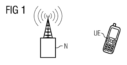
- Figure 1 is a simplified schematic diagram of a communi-
cations network for implementing the method according to
an embodiment of the invention;
- Figure 2 is a simplified schematic diagram of a network
node of a communications network for implementing the
method according to an embodiment of the invention; and
- Figure 3 is a simplified schematic diagram of a mobile
station of a communications network for implementing the
method according to an embodiment of the invention.
DETAILED DESCRIPTION OF EXEMPLARY EMBODIMENTS
Figure 1 shows a radio communications network, which includes
a network node, in this case a base station N, located in a
cell of the network. A mobile station UE, for example a mo-
bile telephone or PDA, can communicate via the base station
N.
The base station N and the mobile station UE are shown sche-
matically in more detail in Figures 2 and 3, respectively.
The base station N includes a transmitter T for transmitting
WO 2011/023595 CA 02805514 2013-01-15 PCT/EP2010/061970
8
data to the rest of the network and a controller C coupled to
the transmitter T. A receiver R is provided for receiving
data from the mobile station UE and other network components,
such as other mobile stations, and is coupled to a detector,
which detects the transmission power level being used by the
mobile station UE. The mobile station UE includes a trans-
mitter TM and a receiver RM, both coupled to a power control
unit PCU. For clarity and simplicity, Figures 1-3 only show
the components required for the invention.
In operation, the transmitter T in the base station N broad-
casts to the mobile station UE on the BCCH channel the maxi-
mum transmission power level allowed in the cell of the net-
work where it is located. Furthermore, the base station N
indicates, by means of an indicator bit on the BCCH channel,
that the network supports the mobile station UE autonomously
reducing its transmission power level. While the receiver RM
of the mobile station UE is receiving the broadcast from the
base station N that the cell maximum transmission power is
allowed, the power control unit PCU of the mobile station UE
starts to autonomously reduce the transmission power of the
mobile station UE at the beginning of transmission by the mo-
bile station UE on a transmission channel (e.g. SDCCH or ICH
in signalling only mode) being used by the transmitter TM for
transmitting data from the mobile station UE. The power con-
trol unit PCU of the mobile station UE continues to autono-
mously reduce the transmission power of the mobile station UE
while the network is broadcasting (via the base station N)
the maximum allowed cell transmission power. The network
will permit the UE to autonomously reduce its transmission
power as long as the maximum cell transmission power is being
broadcast.
WO 2011/023595 CA 02805514 2013-01-15 PCT/EP2010/061970
9
If, however, the allowed cell transmission power is required
to change, for example due to excessive interference in the
cell, the base station N broadcasts a signal containing a mo-
bile station transmit power level that is different from the
maximum allowed in the cell. This signal is received at the
receiver RN of the mobile station UE, which stops the power
control unit PCU of the mobile station UE from autonomously
reducing the transmission power of the mobile station UE on
the transmission channel being used. The controller C of the
base station N then controls the base station transmitter T
to transmit a power command signal, which is received at the
receiver RN of the mobile station UE and controls the power
control unit PCU to adjust the transmission power of the mo-
bile station UE. Control of the transmission power of the
mobile station UE on the transmission channel is then kept by
the network for the rest of the duration of the transmission
channel and the network prevents the mobile station UE from
autonomously reducing its transmission power level on that
channel again.
In an alternative embodiment, the network can modify its
power control procedures so that maximum cell transmission
power plus or minus one power level is signalled by the base
station N instead of maximum power when autonomous power re-
duction is being used by the mobile station UE. In this
case, the detector D in the base station N detects the actual
transmission power being used by the mobile station UE on the
transmission channel so can determine if autonomous power re-
duction is being used by the mobile station UE. If the de-
tector D detects that autonomous power reduction is being
used by the mobile station UE, the controller C can then con-
trol the transmitter T of the base station N to transmit the
cell maximum allowed power plus or minus one power level to
the mobile station UE.
WO 2011/023595 CA 02805514 2013-01-15PCT/EP2010/061970
10
If the network needs to signal the maximum transmission power
allowed in a particular cell, the base station N may command
the mobile station UE, by a signal on the BCCH channel to use
maximum transmission power minus one power control level and
subsequently increase this to a maximum, once the network as-
sumes control of uplink power. Signalling of the power com-
mands from the base station N to the mobile station UE may be
achieved by setting an indicator bit on the BCCH channel, for
example.
Alternatively, the base station N may command the mobile sta-
tion UE to use the maximum transmission power allowed in the
cell plus one power control level. For example, if the cell
maximum transmission power was set at 2W for a GSM 900 net-
work, then at one power control level higher the mobile sta-
tion UE would immediately follow a transmission power of 2W.
If the cell maximum power was set to be lower than this, then
the network would have to revert to the actual cell maximum
power after some time.
Although the invention has been described hereinabove with
reference to specific embodiments, it is not limited to these
embodiments and no doubt further alternatives will occur to
the skilled person that lie within the scope of the invention
as claimed.
For example, the control functionality of the base station
may be located in a separate radio network controller (RNC)
coupled to the base station.