Note: Descriptions are shown in the official language in which they were submitted.
CA 02805826 2013-02-11
TANK MADE OF A COMPOSITE MATERIAL AND CLOSED MOLDING PROCESS FOR
MANUFACTURING THE SAME
FIELD OF THE INVENTION
The present invention relates to tanks, and more particularly to tanks made of
a composite
material and a closed molding process for manufacturing the same.
BACKGROUND OF THE INVENTION
Tanks used in numerous applications such as, for example, oil tanks, water
tanks, compressor
tanks are nowadays made of a composite material such as, for example, a
fiberglass composite
material. Use of a composite material provides a light weight and
substantially corrosion resistant
tank.
State of the art composite material tanks are made using a chopper gun.
Unfortunately, this
process exposes the operator of the chopper gun as well as the environment to
fine particles and
volatile resin components during operation of the chopper gun and,
furthermore, exposes the
uncured resin to the atmosphere. Further disadvantages are an unappealing
finish of the outside
surface of the tank as well as inconsistent quality of the tank depending on
the skill of the
operator.
Another process for producing composite material parts is the vacuum infusion
process, which is
carried out within a closed molding system, i.e. the void between a sealed bag
and a mold, or
between two sealed molds. This process is capable of producing composite
material parts of high
and consistent quality.
Typically, composite material tanks are made in two halves which are joined
together using an
adhesive, resulting in a bond line substantially weakening the tank.
It is desirable to provide a method for manufacturing a composite material
tank in substantially a
Page 1 of 16
CA 02805826 2013-02-11
single piece using a closed molding process.
It is also desirable to provide a composite material tank that is manufactured
in substantially a
single piece using the closed molding process.
SUMMARY OF THE INVENTION
Accordingly, one object of the present invention is to provide a method for
manufacturing a
composite material tank in substantially a single piece using a closed molding
process.
Another object of the present invention is to provide a composite material
tank that is
manufactured in substantially a single piece using the closed molding process.
According to one aspect of the present invention, there is provided a method
for manufacturing a
tank. A first mold having a first molding surface corresponding to a first
portion of an outside
surface of the tank is provided. A second mold having a second molding surface
corresponding
to a second portion of the outside surface of the tank is provided. The first
portion and the second
portion form the outside surface of the tank having an opening disposed
therein. A mold release
agent is disposed onto the first and second molding surface. A molding bladder
is provided. An
outside surface of the molding bladder when inflated substantially corresponds
to an inside
surface of the tank having the opening disposed therein. A reinforcement
material is disposed
onto one of the molding bladder and the molding surfaces. The first and the
second mold are
combined in a sealed fashion. The first and the second mold have accommodated
therebetween
the reinforcement material and the molding bladder. A molding space between
the molding
bladder and the combined first and second mold is sealed. The molding space
contains the
reinforcement material. The molding space is evacuated. The evacuated molding
space is then
filled with a resin. The resin is cured to form a wall of the tank. The
molding bladder is deflated
and removed through the opening. The first and the second mold are separated
and removed from
the tank.
According to another aspect of the present invention, there is provided a
tank. The tank
Page 2 of 16
1
CA 02805826 2013-02-11
comprises a single tank body made as a single piece of a composite material
using a vacuum
infusion process with a first portion of the tank body having an outside
surface corresponding to
a first molding surface of a first mold and a second portion of the tank body
having an outside
surface corresponding to a second molding surface of a second mold. The tank
body has an
opening disposed therein with the opening being substantially smaller than the
tank body. A
fitting member is mounted to a portion of the tank body surrounding the
opening.
The advantage of the present invention is that it provides a method for
manufacturing a
composite material tank in substantially a single piece using a closed molding
process.
A further advantage of the present invention is that it provides a composite
material tank that is
manufactured in substantially a single piece using the closed molding process.
BRIEF DESCRIPTION OF THE DRAWINGS
A preferred embodiment of the present invention is described below with
reference to the
accompanying drawings, in which:
Figures la to ld are simplified block diagrams illustrating a perspective
view, a front
view, a top view, and a side view, respectively, of a domestic oil tank made
of a
composite material according to a preferred embodiment of the invention;
Figure 1 e is a simplified block diagram illustrating a perspective view of a
tank body
made of a composite material according to a preferred embodiment of the
invention;
Figures 2a to 2c are simplified block diagrams illustrating a perspective
view, a cross
sectional view, and a top view, respectively, of a first mold used in a closed
mold vacuum
infusion process according to a preferred embodiment of the invention;
Figure 2d is a simplified block diagram illustrating a cross sectional view of
a second
mold used in the closed mold vacuum infusion process according to a preferred
Page 3 of 16
,
[
CA 02805826 2013-02-11
embodiment of the invention;
Figure 2e is a simplified block diagram illustrating a cross sectional view of
a molding
bladder used in the closed mold vacuum infusion process according to a
preferred
embodiment of the invention;
Figure 2f is a simplified block diagram illustrating a cross sectional view of
the first mold
with the molding bladder used in the closed mold vacuum infusion process
according to a
preferred embodiment of the invention;
Figure 2g is a simplified block diagram illustrating a cross sectional view of
the
combined first and second mold with the molding bladder used in the closed
mold
vacuum infusion process according to a preferred embodiment of the invention;
Figure 2h is a simplified block diagram illustrating the resin flow in a cross
sectional
view of the combined first and second mold with the molding bladder used in
the closed
mold vacuum infusion process according to a preferred embodiment of the
invention;
Figure 2i is a simplified block diagram illustrating in a cross sectional view
the removal
of the molding bladder from the tank body in the closed mold vacuum infusion
process
according to a preferred embodiment of the invention;
Figures 3a and 3b are simplified block diagrams illustrating in cross
sectional views
insertion and mounting of the fitting member in the closed mold vacuum
infusion process
according to a preferred embodiment of the invention; and,
Figure 4 is a simplified block diagram illustrating a top view of a first mold
used in a
closed mold vacuum infusion process according to another preferred embodiment
of the
invention.
DESCRIPTION OF THE PREFERRED EMBODIMENT
Page 4 of 16
,
CA 02805826 2013-02-11
Unless defined otherwise, all technical and scientific terms used herein have
the same meaning as
commonly understood by one of ordinary skill in the art to which the invention
belongs.
Although any methods and materials similar or equivalent to those described
herein can be used
in the practice or testing of the present invention, the preferred methods and
materials are now
described.
While embodiments of the invention will be described for manufacturing an oil
tank for domestic
use, it will become evident to those skilled in the art that the embodiments
of the invention are
not limited thereto, but are also adaptable for manufacturing various other
types of tanks such as,
for example, water tanks, compressor tanks, and propane tanks for domestic use
as well as
industrial use. Furthermore, it will become evident to those skilled in the
art that the
embodiments of the invention are not limited to the employment of fiberglass
as reinforcement
material, but are adaptable to the use of various other reinforcement
materials such as, for
example, carbon fiber.
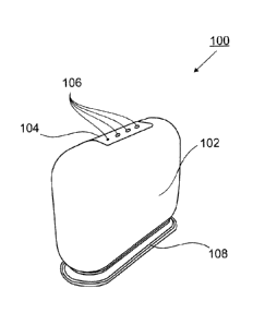
Referring to Figures la to le, a domestic oil tank 100 made of a composite
material according to
a preferred embodiment of the invention is provided. The tank 100 comprises a
single tank body
102 made as a single piece of a composite material using a closed molding
process according to a
preferred embodiment of the invention described hereinbelow. The tank body 102
has an opening
110 disposed therein. Preferably, the opening 110 is substantially smaller
than the tank body 102
and is covered by a fitting member 104 mounted to a portion of the tank body
102 surrounding
the opening 110 with the fitting member 104 having, for example, fittings 106
for being
connected to: a fill pipe; a vent pipe; a supply pipe; and a level gauge.
Further preferably, the
tank 100 comprises a base member 108 mounted to a bottom portion of the tank
body 102.
The tank body 102 is designed to enable manufacture using a closed mold vacuum
infusion
process according to a preferred embodiment of the invention provided
hereinbelow with
reference to Figures 2a to 2i. A first portion of the tank body 102 has an
outside surface 114A
corresponding to a first molding surface 204A of a first mold 202A and a
second portion of the
tank body 102 has an outside surface 114B corresponding to a second molding
surface 204B of a
Page 5 of 16
CA 02805826 2013-02-11
second mold 202B. The outside surfaces 114A and 114B are designed ¨ based on
standard
molding technology - such that during the molding process the molds 202A and
202B are in
contact at seam 112 and can be separated and removed from the outside surfaces
114A and 114B
after curing of the tank body 102. The outside surfaces 114A and 114B
illustrated in Figure le
are symmetric with respect to the seam 112. As is evident to one skilled in
the art, while
facilitating the design and manufacture of the molds 202A, 202B, it is not
necessary for the
outside surfaces 114A and 114B to be symmetric, i.e. the outside surfaces 114A
and 114B can be
of different shape as long as they can be combined at the seam 112.
Referring to Figures 2a to 2i a closed mold vacuum infusion process according
to a preferred
embodiment of the invention is provided. Based on the outside surfaces 114A
and 114B of the
tank body 102, molds 202A and 202B are designed and provided. Preferably, the
molds 202A
and 202B are designed simultaneously with the outside surfaces 114A and 114B
of the tank body
102. The molds 202A, 202B comprise the molding surfaces 204A, 204B surrounded
by sealing
flanges 206A, 206B with a portion 208A, 208B being recessed corresponding to
the opening 110.
Flange seal 212 is disposed on the flange 206A to provide seal space 214
therebetween which is,
preferably, sealed in an airtight fashion. Furthermore, opening seals 216A,
216B are disposed on
the recessed flange portions 208A, 208B to provide seal spaces 218A, 218B,
respectively.
Evacuation port 222 is disposed in flange 206A and designed for being
connected to a vacuum
pump. Preferably, the molds 202A, 202B are made of a fiberglass material
having sufficient wall
thickness to provide sufficient rigidity to the molds 202A, 202B for executing
the molding
process absent deformation of the same. Of course, other materials such as
metals are also
applicable, but the fiberglass material is preferred for providing sufficient
rigidity while being
lightweight for facilitating handling of the molds.
In a first step of the closed mold vacuum infusion process the molding
surfaces 204A, 204B are
coated with a release agent to aid in the separation of the molding surfaces
204A, 204B from the
outside surfaces 114A and 114B of the tank body 102 after curing and to reduce
imperfections in
the molding surfaces 204A, 204B in order to provide smooth outside surfaces
114A and 114B.
Preferably, the molding surfaces 204A, 204B are coated with a thin layer -
approximately 0.5 mm
- of ENGUARD FR SERIES FIRE RETARDANT ISO/NPG GELCOAT.
Page 6 of 16
,
CA 02805826 2013-02-11
Next, the reinforcement material is placed onto the molding surfaces 204A,
204B. Preferably, the
reinforcement material is a layer of fiberglass fabric. Further preferably, a
fiberglass fabric with a
thermo set powder in the glass such as, for example, UM-720 fiberglass fabric,
is employed.
Further preferably, the fiberglass fabric is preformed to correspond to the
molding surfaces 204A,
204B such that each molding surface is covered with one layer of fabric 220A,
220B and such
that the fabric layer 220A disposed in mold 202A is protruding the mold 202A a
predetermined
distance D ¨ for example, 3 inches ¨ producing an overlap of the layers 220A,
220B of the same
distance, as illustrated in Figures 2b and 2g. The predetermined distance D is
designed to provide
sufficient strength to the tank body 102 at the seam 112 depending, for
example, on the size of
the tank body 102 and an inside pressure range the tank body 102 is designed
to withstand.
Optionally, more than one layer of the reinforcement material is disposed on
each molding
surface. Further optionally, the layers are designed such that different
layers overlap at a different
location in order to further increase the strength of the tank body 102.
Alternatively, other
reinforcement materials are employed such as, for example, carbon fiber or
various organic fibers
or combinations thereof known to one skilled in the art. Optionally, the
fabric layers 220A, 220B
are secured to the respective mold surfaces 204A, 204B using a commercially
available spray
adhesive such as, for example, a styrene based spray adhesive for temporarily
bonding light and
medium weight fiber reinforcements.
After placement of the reinforcement material, molding bladder 302 is placed
into the mold
202A onto reinforcement layer 220A and inflated to a pressure such that an
outside surface 304
of the molding bladder corresponds approximately to an inside surface of the
tank body 102 and
is capable of holding the reinforcement layer 220A in place, as illustrated in
Figure 2f, as well as
the reinforcement layer 220B after combining the molds 202A and 202B in a
later step.
Alternatively, the reinforcement layer 220B is placed onto the molding bladder
302 instead of
being placed into the mold 202B.
The molding bladder 302, illustrated in Figure 2e, is designed such that
during the molding
process an outside surface 304 of the inflated molding bladder 302
substantially corresponds to
an inside surface of the tank body 102 having the opening 110 disposed
therein. Furthermore, the
Page 7 of 16
CA 02805826 2013-02-11
molding bladder 302 comprises a sealing extension 306 for providing, in
concert with the
opening seals 216A, 216B, an airtight seal between the bladder 302 and the
molds 202A, 202B.
Resin injection conduit 318 is disposed inside the molding bladder 302 and
connected to resin
injection port 316 and resin injection aperture 320. The molding bladder 302
is inflated by
providing a compressed fluid such as compressed air via inflating port 308.
Evacuating conduit
311 is disposed in the sealing extension 306 and connected to evacuating
openings 312 and 314
and evacuating port 310 for being connected to a vacuum pump. The molding
bladder 302 is
made of a flexible material such as, for example, a silicone rubber material
for enabling re-use of
the same. The evacuating conduit 311 and the resin injection conduit 318 are
made of a flexible
material such as, for example, a silicone rubber material or, alternatively, a
rigid material.
After placing and inflating the molding bladder 302, the molds 202A, 202B are
combined and
sealed in a substantially airtight fashion by evacuating the seal space 214
via evacuation port 222
to a predetermined vacuum, preferably, a low vacuum of approximately 3000 Pa.
Alternatively,
the the molds 202A, 202B are combined and sealed in a substantially airtight
fashion by
clamping the flanges using, for example, a plurality of clamps. Further
alternatively, inflation of
the molding bladder 302 is omitted in case the fabric layers 220A, 220B are
secured to the
respective mold surfaces 204A, 204B using, for example, a Tack Spray Adhesive
and the sealing
extension 306 is designed to provide a proper seal absent inflation of the
molding bladder 302.
Further alternatively, the molding bladder 302 is inflated to net shape and
the reinforcement
material is then disposed onto the outside surface 304 of the molding bladder
302 using the Tack
Spray Adhesive. The molding bladder 302 with the reinforcement material is
then placed onto
molding surface 204A of mold 202A followed by placement of mold 202B
thereupon. Provision
of the reinforcement material onto the outside surface of the molding bladder
302 removes the
restriction of providing the reinforcement material in two sections with each
section substantially
corresponding to one of the molding surfaces 204A, 204B resulting in an
overlap in proximity to
the seam 112.
Next, molding space 322 between the outside surface 304 of the molding bladder
302 and the
molding surfaces 204A, 204B, containing the reinforcement layers 220A, 220B,
as well as seal
Page 8 of 16
CA 02805826 2013-02-11
spaces 218A, 218B are evacuated to a predetermined vacuum, preferably, to a
low vacuum of
approximately 3000 Pa via evacuating openings 314 and 312, respectively.
Evacuation via
evacuating opening 312 provides a substantially airtight seal between the
recessed flange
portions 208A, 208B of the molds 202A, 202B and the sealing extension 306 of
the molding
bladder 302, while evacuation via evacuating opening 314 evacuates the molding
space 322
including spaces between fibers of the reinforcement material 220A, 220B to
ensure penetration
of the same by the resin provided in the following step. Preferably, the
molding bladder 302 is
designed such that the outside surface 304 of the molding bladder 302
substantially corresponds
to the inside surface of the tank body 102 when the molding space 322 is
evacuated to the low
vacuum of approximately 3000 Pa.
Once the molding space 322 is evacuated to the predetermined vacuum, the resin
- for example, a
vinyl ester resin or epoxy resin - is injected into the molding space 322 via
resin injection
aperture 320 while evacuation of the molding space 322 is continued.
Preferably, the resin is ISO
FLAME RETARDANT DION FR 7767-80. The resin injected via resin injection
aperture 320 is
then drawn by the vacuum throughout the molding space 322 including the spaces
between fibers
of the reinforcement material 220A, 220B towards the evacuating opening 314
located at a
substantially opposite end portion of the molding space 322 from the location
of the resin
injection aperture 320, as indicated by the arrows in Figure 2h, until the
resin has reached the
evacuating opening 314 or, alternatively, until the resin is drawn through
evacuating conduit 311
and evacuating port 310 into, for example, a resin trap interposed between a
vacuum pump and
evacuating port 310. Optionally, a plurality of resin injection apertures are
provided, with all
resin injection apertures being placed substantially opposite to the
evacuating opening 314 or
with some resin injection apertures being placed between the location of the
resin injection
aperture 320 and the evacuating opening 314, for example, placed in a
midsection of the molding
bladder 302. Further optionally, the resin is injected into the molding space
322 under pressure
with the pressure being determined such that the molding bladder 302 can
withstand the same
absent deformation. Further optionally, the pressure in the molding bladder
302 is increased such
that the molding bladder 302 is capable to withstand the pressure of the
injected resin absent
deformation.
Page 9 of 16
CA 02805826 2013-02-11
During the curing process, the temperature of the resin continuously increases
while the resin
progresses through a gel stage followed by a hardening stage until a peak
temperature ¨ called
"peak exotherm" - is reached. The peak exotherm temperature depends on the
resin and the
laminate - or wall - thickness with the peak exotherm temperature being higher
with increasing
thickness. Preferably, the temperature is measured in proximity to the
location of the resin
injection aperture 320 since at this location the resin starts to gel first
due to the increased wall
thickness, i.e. mass. The temperature of the resin is measured using, for
example, a commercially
available infrared gun, enabling measurement through the molding bladder 302
with the molding
bladder 302 being made of a transparent material.
Once the peak exotherm temperature is reached, the molding bladder 302 is
deflated and
removed through the opening 110, as illustrated in Figure 2i. The opening 110
illustrated in
Figure 1 e is designed to accommodate the fitting member 104 containing all
the fittings 106 and,
therefore, is larger than needed to remove the molding bladder 302. The size
of the opening 110
needed for removing the molding bladder 302 depends on the shape, size, and
material of the
molding bladder 302.
After removal of the molding bladder 302 the seal space 214 is vented in order
to separate the
molds 202A and 202B and to remove the same from the tank body 102, thus
releasing the tank
body 102.
Preferably, the reinforcement layers 220A, 220B are preformed to correspond to
the molding
surfaces 204A, 204B and to have a constant thickness throughout for providing,
in concert with
the outside surface 304 of the molding bladder 302, a constant wall thickness
of the tank body
102, with the exception of the location of the overlap of the reinforcement
layers 220A, 220B.
The wall thickness of the tank body 102 is approximately the same as the
thickness of the
reinforcement layers 220A, 220B and double at the location of the overlap of
the reinforcement
layers 220A, 220B. The contact of the reinforcement layers 220A, 220B with the
outside surface
304 of the molding bladder 302 allows the resin to transfer evenly throughout
the reinforcement
layers 220A, 220B. With the preformed reinforcement layers 220A, 220B having a
substantially
constant fiber-to-void ratio the amount of resin used for manufacturing the
tank body 102 is
Page 10 of 16
CA 02805826 2013-02-11
substantially the same resulting in a substantially repeatable process for
producing tank bodies
102 having substantially same dimensions, weight, and strength.
Fitting member 104 comprising fittings 106 is then mounted in a sealed fashion
to the tank body
102. The fitting member 104 is, for example, manufactured using a standard
vacuum infusion
process with the fittings 106 being commercially available Fiberglass
Reinforced Plastic (FRP)
fittings mounted to previously drilled openings in the fitting member 104
using an epoxy
adhesive. As illustrated in Figure 3a, the fitting member 104 is passed
through the opening 110
with fitting member 104 and the opening 110 having a corresponding elongated
shape. Inside the
tank body 102, the fitting member 104 is then turned and inserted into the
opening 110 such that
flange 105 of the fitting member is in contact with a portion of the inside
surface of the tank body
102 surrounding the opening 110, as illustrated in Figure 3b. Preferably, the
fitting member 104
is mounted to the tank body 102 using an adhesive such as, for example, an
epoxy adhesive,
which is disposed onto the flange 105 prior insertion into the tank body 102.
Preferably, the
epoxy adhesive employed is PLIOGRIP EPDXY 5760B. After insertion into the
opening 110 the
flange 105 of the fitting member 104 is pushed towards the tank body 102 and
hold in place
during curing of the adhesive, for example, by providing compressed air into
the tank body 102
at a pressure of, for example, 35000 Pa above outside pressure. The flange is
designed to be
sufficiently wide for providing a proper seal when mounted to the tank body
102 having, for
example, a width of approximately 50 mm.
Alternatively, the fitting member 104 is mounted to the outside surface of the
tank body 102, for
example, when the tank 100 is designed for being operated at an inside
pressure that is below a
pressure the outside of the tank 100 is exposed to.
Finally, the base member 108 - for example, manufactured using a standard
vacuum infusion
process - is mounted to a bottom portion of the tank body 102 using, for
example, an epoxy
adhesive.
The closed mold vacuum infusion process according to a preferred embodiment of
the invention
has been applied for manufacturing a 1000 1 domestic oil tank, illustrated in
Figures la to le,
Page 11 of 16
CA 02805826 2013-02-11
having: height H of 1229 mm; length L of 1715 mm; width W of 602 mm; and wall
thickness of
4.8 mm. The opening 110 has a length of 787 mm and a width of 203 mm and was
designed to
accommodate the fitting member 104 containing all the fittings 106, i.e. the
opening 110 is larger
than needed for removing the molding bladder 302.
As is evident the closed mold vacuum infusion process according to a preferred
embodiment of
the invention is adaptable for manufacturing composite material tank bodies
having various
shapes and sizes.
Referring to Figure 4, another embodiment of the closed mold vacuum infusion
process is
provided. Here, the tank body is designed such that the opening 410 for
removing the molding
bladder is placed in the molding surface 404A of a single mold 402A. The
processing steps are
substantially the same. A reinforcement layer, having an opening corresponding
to the opening
410, is placed into the mold 402A. The molding bladder is then placed onto the
reinforcement
layer with the sealing extension being accommodated in the opening 410 and
inflated. Another
reinforcement layer is then placed onto the inflated molding bladder followed
by a second mold
associated with the mold 402A. The following steps are then executed in a same
fashion as
described hereinabove.
The present invention has been described herein with regard to preferred
embodiments. However,
it will be obvious to persons skilled in the art that a number of variations
and modifications can
be made without departing from the scope of the invention as described herein.
Page 12 of 16