Note: Descriptions are shown in the official language in which they were submitted.
WO 2012/012613 CA 02806040 2013-01-18 PCT/US2011/044815
-1-
TITLE: WELLBORE TOOL WITH EXCHANGABLE BLADES
INVENTOR(s): HERBERG, Wolfgang E.; and GRUETZMANN, Ines
BACKGROUND OF THE DISCLOSURE
1. Field of the Disclosure
[0001] This disclosure relates generally to oilfield downhole tools and
more particularly to efficiently deploying well tools.
2. Background of the Art
[0002] Boreholes or wellbores are drilled by rotating a drill bit attached
to the bottom of a drilling assembly (also referred to herein as a "Bottom
Hole
Assembly" or ("BHA"). The BHA may be attached to the bottom of a tubing or
tubular string, which is usually either a jointed rigid pipe (or "drill pipe")
or a
relatively flexible spoolable tubing commonly referred to in the art as
"coiled
tubing." The string comprising the tubing and the drilling assembly is usually
referred to as the "drill string." When jointed pipe is utilized as the
tubing, the
drill bit is rotated by rotating the jointed pipe from the surface and/or by a
motor contained in the drilling assembly. In the case of a coiled tubing, the
drill bit is rotated by the motor.
[0003] In certain instances, it may be desirable to enlarge a diameter of
a section of a borehole with a hole opener. This borehole section may be an
open hole or lined with a wellbore tubular such as a liner or casing. The
present disclosure address the need for efficiently deploying hole openers
and other tools for wellbore operations.
SUMMARY OF THE DISCLOSURE
[0004] In aspects, the present disclosure provides a method for
conducting a wellbore operation that includes using a radially projecting
member in a wellbore, the radially projecting member being positioned on a
first sub; and disconnecting the radially projecting member from the first sub
WO 2012/012613 CA 02806040 2013-01-18PCT/US2011/044815
-2-
without uncoupling a second sub from the first sub. The method may include
also coupling the first sub to the second sub with a connector that includes
an electrical connection. The method may further include enlarging a
diameter of a wellbore using the member, retrieving the first sub from a
wellbore, and / or disconnecting the radially projecting member at a rig
positioned over the wellbore.
[0005] In aspects, the present disclosure provides a method for
conducting a wellbore operation that includes: connecting a conductor of the
first sub to a conductor of the second sub; conveying the first sub and the
second sub into a wellbore; cutting a surface in the wellbore using a
plurality
of cutters positioned in the first sub; transmitting signals along the
conductors
while the first and the second sub are in the wellbore; retrieving the first
sub
and the second sub to the surface; and replacing at least one cutter of the
plurality of cutters with a replacement cutter while the conductors of the
first
sub and the second sub are connected to one another; and conveying the
first sub and the second sub again into the wellbore without uncoupling the
conductors of the first sub and the second sub.
[0006] In aspects, an apparatus for performing a wellbore operation
may include a sub having at least one conductor connected to a connector;
and at least one radially projecting member removably coupled to the sub. In
another embodiment, an apparatus for performing wellbore operations may
include a section of a drill string that includes a first sub and a second
sub.
The first sub may include at least one conductor, a connector connected to
the at least one conductor; and at least one radially projecting member
coupled to the first sub. The at least one radially projecting member may be
removed from the first sub while the first sub is connected to the second sub.
[0007] Examples of certain features of the disclosure have been
summarized rather broadly in order that the detailed description thereof that
follows may be better understood and in order that the contributions they
represent to the art may be appreciated. There are, of course, additional
features of the disclosure that will be described hereinafter and which will
WO 2012/012613 CA 02806040 2013-01-18PCT/US2011/044815
-3-
form the subject of the claims appended hereto.
BRIEF DESCRIPTION OF THE DRAWINGS
[0008] For a detailed understanding of the present disclosure,
reference should be made to the following detailed description of the
embodiments, taken in conjunction with the accompanying drawings, in
which like elements have been given like numerals, wherein:
FIG. 1 illustrates a wellbore construction system made in accordance
with one embodiment of the present disclosure;
FIG. 2 schematically illustrates a BHA that includes a hole enlargement
device made in accordance with one embodiment of the present disclosure;
and
FIG. 3 illustrates a top view of the hole enlargement device of FIG. 2.
DETAILED DESCRIPTION OF THE DISCLOSURE
[0009] In aspects, the present disclosure provides a cutting structure
that may be replaced without breaking the connections between a tool sub
supporting that cutting structure and adjacent subs or joints. As used herein,
the term "sub" broadly refers to any structure that can support one or more
components, tools, or devices. A "sub" may be of any shape or configuration,
may be skeletal, or a complete enclosure. Moreover, a "sub" may be open to
the environment or a sealed enclosure. Also, the "sub" is not limited to any
particular material or method of manufacture. Cutting structures experience
wear during use. In instances where the tool sub is in an assembly that uses
electrical and data connections, breaking the electrical / data connections
can be time consuming and can compromise the operational integrity of
these connections. As will become apparent from the disclosure below,
embodiments of the present disclosure allow a tool sub having cutting
structures to be serviced at a rig or other suitable work area without
breaking
one or more of these connections.
WO 2012/012613 CA 02806040 2013-01-18PCT/US2011/044815
-4-
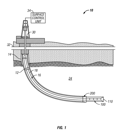
[0010] FIG. 1 is a schematic diagram showing a drilling system 10 for
drilling wellbores according to one embodiment of the present disclosure.
FIG. 1 shows a wellbore 12 that includes a casing 14 with a drill string 16.
The drill string 16 includes a tubular member 18 that carries a bottomhole
assembly (BHA) 100 at a distal end. The tubular member 18 may be made
up by joining drill pipe sections. The drill string 16 extends to a rig 30 at
the
surface 32. The drill string 16, which may be jointed tubulars or coiled
tubing,
may include power and/or data conductors such as wires for providing
bidirectional communication and power transmission. A top drive (not
shown), or other suitable rotary power source, may be utilized to rotate the
drill string 16. A controller 34 may be placed at the surface 32 for receiving
and processing downhole data. The controller 34 may include a processor, a
storage device for storing data, and computer programs. The processor
accesses the data and programs from the storage device and executes the
instructions contained in the programs to control the drilling operations.
[0011] Referring now to FIG. 2, in one embodiment, the BHA 100 may
include a drill bit 110, a steering device 120, a drilling motor 130, a sensor
sub 140, a bidirectional communication and power module (BCPM) 150, a
stabilizer 160, a formation evaluation (FE) module 170, and a hole
enlargement device 200. Each of these devices and components may be
considered "subs." Some or all of these devices use electrical power and
transmit / receive data signals. To enable power and/or data transfer across
the subs of the BHA 100, the BHA 100 may include one or more power
and/or data transmission lines 180. The power and/or data transmission line
180 may extend along the entire length of the BHA 100. The lines 180 may
be embedded or separate conductors made of metal wires, optical fibers, or
any other suitable data conveying media. The joints or ends of the subs of
the BHA 100 may include suitable connectors 190 to establish power and / or
data transmission at the mating portions of the subs making up the BHA 100.
Exemplary connectors 190 may include slip rings and other suitable
connection devices. For example, a sub or drill pipe may include insulated
contact rings positioned in a shoulder at both ends of the pipe (e.g., the
WO 2012/012613 CA 02806040 2013-01-18PCT/US2011/044815
-5-
threaded pin and box ends). The contact rings in the sub or pipe body may
be connected by a conductor (e.g., line 180) that spans the length of the
body. Thus, when a pipe body is made up with an adjoining segment of pipe,
the contact ring in the first segment of pipe makes contact with a
corresponding contact in the adjacent pipe section.
[0012] Referring now to FIG. 3, there is shown a top view of one
embodiment of a hole enlargement device 200 in accordance with the
present disclosure. These devices may also be referred to as hole openers.
The hole enlargement device 200 may include expandable cutters 202 that
are circumferentially disposed in a sub or housing 204. The cutters 202 may
be disposed in a bay or pocket 206 that is open to the environment. The
cutters 202 may be extended substantially simultaneously to form a wellbore
having a generally circular cross-sectional shape. That is, the cutters 202 do
not preferentially cut the wellbore wall, because such a cutting action would
yield an asymmetric cross-sectional shape (e.g., a non circular shape). When
projected radially, the cutters 202 scrape, break-up and disintegrate the
wellbore surface formed initially by the drill bit 110 (FIGS. 1 and 2). In one
arrangement, a stop block 208 is positioned on the housing 204 to engage
the cutters 202. The cutters 202 have cutting elements 210 disposed on one
end 212. On the opposing end 214, the cutters 202 are fixed to a translating
member 216. When actuated, the translating members 216 push the cutters
202 along a ramped surface (not shown) until the end 212 of the cutters 202
touch the stop block 208. As the cutters 202 slide axially in the pocket 206,
the ramped (not shown) surface pushes the cutters 202 radially outward.
The travel of the cutters 202, and the diameter of the hole formed, may be
adjusted by shifting the location of the stop block 208. Fasteners 218 may
be used to secure the stop block 208 to the housing 204 and the translating
members 216 to a moving sleeve (not shown) inside the housing. The term
"radially projecting member" generally refers to any member that extends out
beyond the outer circumferential surface of a sub or housing.
[0013] Referring now to FIG. 2, the cutters 202 may, in real-time, be
WO 2012/012613 CA 02806040 2013-01-18PCT/US2011/044815
-6-
extended and retracted by an actuation unit 220 that moves the sleeve (not
shown) and translating members 216 (FIG. 3). In one arrangement, the
actuation unit 220 utilizes pressurized hydraulic fluid as the energizing
medium. For example, the actuation unit may include a piston disposed in a
cylinder, an oil reservoir, and valves that regulate flow into and out of the
cylinder. The hydraulic fluid may be pressurized using pumps and/or by the
pressurized drilling fluid flowing through the bore of the drill string 16. An
electronics package 222 controls valve components such as actuators in
response to surface and/or downhole commands and transmits signals
indicative of the condition and operation of the hole enlargement device 200.
Position sensors (not shown) may provide an indication as to the radial
position of the cutters 202. The electronics package 222 may communicate
with the BCPM 150 via a line 180. Thus, for instance, surface personnel may
transmit instructions from the surface that cause the electronics package 222
to operate the valve actuators for a particular action (e.g., extension or
retraction of the cutting elements 210). A signal indicative of the position
of
the cutters 202 may be transmitted via the line 180 to the BCPM 150 and,
ultimately, to the surface.
[0014] It should be appreciated that surface personnel can activate the
hole enlargement device 200 to expand / retract a plurality of times during a
single trip of the BHA 100 in the well.
[0015] Referring now to Figs. 1 and 2, in one method of use, when it is
desired to replace one or more cutters 202, the drill string 16 is retrieved
to
the surface ( or 'tripped up' the surface). This process usually involves
removing stands of pipe from the drill string 16. Once the BHA 100 is
accessible to surface personnel, the BHA 100 may be secured without
breaking the connections 190 of the subs making up the BHA 100, which as
noted previously, may have relatively sensitive electrical / fiber optic
connections. Specifically, one or both of the connections 190 associated with
the housing 204 remain connected to adjacent subs to which they are
connected. Thus, the integrity of these connections may be preserved. That
WO 2012/012613 CA 02806040 2013-01-18PCT/US2011/044815
-7-
is, these connections may still be capable of conveying information bearing
signals (e.g., EM, electrical, optical, etc.)
[0016] Referring now to FIG. 3, personnel may next remove the
fasteners 218 and stop block 208 and slide the cutter 202 and the translation
members 216 axially along the pockets 206. A replacement cutter 202 may
now be installed into the hole enlargement device 200. Once the necessary
cutters 202 have been removed and replaced, the BHA 100 may be
conveyed or 'tripped' into the well and further well operations may
commence. Thus, the hole enlargement device 200 has been serviced
without subjecting the signal connection between the subs to service-related
stresses. It should be understood that the fasteners 218 or other fastening
device used is accessible to surface personnel without disassembling the
hole enlargement device 200. It should also be appreciated that the cutter
replacement activity described above minimizes the impact of this operation
on the electrical connections associated with the BHA 100.
[0017] Hole openers or hole enlargement devices in accordance with
the present disclosure may be used to form a wellbore having a diameter
larger than that formed by the drill bit in a variety of applications. For
instance, in some applications, constraints on wellbore geometry during
drilling may result in a relatively small annular space in which cement may
flow, reside and harden. In such instances, the annular space may need to
be increased to accept an amount of cement necessary to suitably fix a
casing or liner in the wellbore. In other instances, an unstable formation
such
as shale may swell to reduce the diameter of the drilled wellbore. To
compensate for this swelling, the wellbore may have to be drilled to a larger
diameter while drilling through the unstable formation. Furthermore, it may be
desired to increase the diameter of only certain sections of a wellbore in
real-
time and in a single trip. In still other instances, sidetracking operations
may
require forming an open hole section in a cased wellbore.
[0018] It should be understood, however, that the present disclosure is
not limited to replacing cutters for hole enlargement devices such as
WO 2012/012613 CA 02806040 2013-01-18
PCT/US2011/044815
-8-
reamers. For example, referring to FIG. 2, in some embodiments, the hole
enlargement device 200 may use arms or pads that do not include cutters.
Rather, the hole enlargement device 200 may use extensible members that
engage a surface of an expandable wellbore tubular to expand the diameter
of such a tubular. In still other embodiments, the stabilizer 160 may be
modified to use replaceable blades or extensible members. In yet other
embodiments, a steering device 120 that uses extensible pads 122 may be
configured to have the pads removable as described above. Pads, blades,
and cutters are illustrative of members that project radially out of a sub. In
any of these embodiments, it should be appreciated that the pads, blades, or
other extensible member may be replaced without disconnecting a
connection that has sensitive elements such as electrical components.
[0019] From the above, it should be appreciated that what has been
described includes, in part, a method for conducting a wellbore operation that
includes disconnecting a radially projecting member from a first sub without
uncoupling a second sub from the first sub. The method may also include
coupling the first sub to the second sub with a connector that includes an
electrical connection. The method may further include enlarging a diameter
of a wellbore using the member, retrieving the first sub from a wellbore, and
/
or disconnecting the first sub at a rig positioned over the wellbore. An
associated apparatus may include a sub having at least one conductor
connected to a connector; and at least one radially projecting member
removably coupled to the sub.
[0020] While the foregoing disclosure is directed to certain
embodiments of the disclosure, various modifications will be apparent to
those skilled in the art. It is intended that all variations within the scope
of the
appended claims be embraced by the foregoing disclosure.