Note: Descriptions are shown in the official language in which they were submitted.
CA 02806234 2014-08-18
- =
- -
CONTROLLED RELEASE AND RECAPTURE
PROSTHETIC DEPLOYMENT DEVICE
[0001] This paragraph intentionally left blank.
TECHNICAL FIELD
[0002] This invention relates to a medical device and, in
particular to a
delivery device for a self-expanding prosthesis and a method of delivering
and deploying the prosthesis into a body lumen.
BACKGROUND
[0003] A self-expanding prosthesis such as a stent may be introduced
into a patient's body using a delivery device that includes a push-pull
mechanism with an outer catheter coaxially slidably disposed over an inner
catheter. The prosthesis is disposed in a circumferentially-restrained
configuration at the distal end of the device between the inner catheter and
the outer catheter. The prosthesis may be deployed by proximally pulling
back the outer catheter relative to the inner catheter, exposing the
prosthesis and allowing it to deploy/ circumferentially expand.
[0004] The push-pull delivery device described above may have several
shortcomings. For example, when using this conventional push-pull
delivery device, a physician may inadvertently retract the outer catheter too
far and prematurely deploy the prosthesis in an incorrect position within a
body lumen. In that circumstance, repositioning the prosthesis may be
difficult, if not impossible, because the prosthesis already will have
radially
self-expanded and engaged the body lumen.
[0005] Accordingly, there is a need for a delivery system that can
increase the control, accuracy and ease of placement during deployment
of a prosthesis. The embodiments described below may be useful for
CA 02806234 2013-01-21
WO 2012/015782 PCT/US2011/045282
- 2 -
increasing the control, accuracy and ease of placement during deployment
of the prosthesis and may also solve other problems.
SUMMARY
[0006] Accordingly, a delivery device is provided including a fixed outer
catheter sheath and a longitudinally-movable pusher member that is
configured to retract/advance in proximal/distal directions for deploying and
recapturing/ resheathing an intraluminal prosthesis.
BRIEF DESCRIPTION OF THE DRAWINGS
[0007] Embodiments are described by way of example with reference to
the accompanying drawings, in which:
[0008] FIGS. 1A-1C show a partial section view of a delivery device
embodiment and method of use;
[0009] FIGS. 2A-2B show a diagrammatic section view of plate/ pusher
member interaction;
[0010] FIGS. 3A-3B show a partial section view of another delivery
device embodiment and method of use; and
[0011] FIGS. 4A-4C show a partial section view of another delivery
device embodiment and method of use.
DETAILED DESCRIPTION OF THE PREFERRED EMBODIMENTS
[0012] The embodiments are described with reference to the drawings
in which like elements are generally referred to by like numerals. The
relationship and functioning of the various elements of the embodiments
may be understood by reference to the drawings and the following detailed
description. However, the embodiments described below are provided by
way of example only, and the invention is not limited to the embodiments
illustrated in the drawings. It should also be understood that the drawings
are not to scale, and ¨ in certain instances ¨ details have been omitted that
are not necessary for an understanding of the embodiments such as
conventional details of fabrication and assembly.
CA 02806234 2014-08-18
- =
=
- 3 -
[0013]
Throughout the specification, the terms "distal" and "distally" shall
denote a position, direction, or orientation that is generally away from the
physician (including any other person holding/ operating a device) and/or
toward a treatment zone/patient. Accordingly, the terms "proximal" and
"proximally" shall denote a position, direction, or orientation that is
generally towards the physician. In FIGS. 1A-1C, 3A-3C, and 4A-4C,
"distal" is generally to the right, and "proximal" is generally to the left.
Various other constructions of deployment devices and methods may be
understood with reference to U.S. Pat. Pub. No. U.S. 2010/0168834 to
Ryan et al., filed Dec. 29, 2009.
[0014] Referring now to the drawings in FIGS. 1A-4C, embodiments of a
delivery device for deploying a self-expanding prosthesis are shown. As
will be discussed, the delivery device is configured with the ability to
resheath and reposition the prosthesis, thereby substantially increasing the
control and accuracy of a deployment process as compared with
conventional delivery devices.
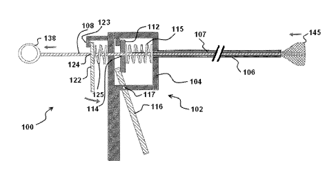
[0015] FIGS. 1A-1C show one embodiment of a delivery device 100,
with reference to a method of use. The delivery device 100 includes a
handle 102 with a handle body 104 and an elongate tubular sheath 106
fixedly attached to and extending distally from the handle body 104. An
elongate pusher member 108 extends slidably through a longitudinal
lumen 107 of the sheath 106. The handle body 104 is shown in a
longitudinal cutaway view revealing the internal components of the
handle 102.
[0016] The interior of the handle 102 includes an advancement plate
member 112 that is biased toward the proximal end of the pusher
member 108. In this embodiment, the advancement member 112 is shown
as being biased by a coil spring 115, but other biasing means known in the
art may be used. The advancement member 112 includes an
advancement member aperture 114 through its thickness, through which
the pusher member 108 extends. A trigger member 116 is pivotably
CA 02806234 2013-01-21
WO 2012/015782 PCT/US2011/045282
- 4 -
mounted to the handle body 104 and is connected to or otherwise
disposed in operative contact with the advancement member 112. When
the pivot axis 117 is configured as shown, pivoting the lower portion of the
trigger member 116 proximally toward the handle body 104 will pivot the
upper portion of the trigger member 116 distally, pushing the advancement
member 112 distally. When advanced distally by motivation from the
trigger member 116, the advancement member 112 engages (in the
manner described below with reference to FIGS. 2A-2B) and pushes
distally the pusher member 108.
[0017] A keeper plate member 122 is also mounted to the handle
body 104 and biased toward its proximal end against a keeper stop 123.
In this embodiment, the keeper member 122 is shown as being biased by
a coil spring 125, but other biasing means known in the art may be used.
The keeper member 122 includes a keeper member aperture 124 through
its thickness, through which the pusher member 108 extends. The keeper
member functions as a "parking brake" or retaining means that will prevent
proximal movement of the pusher member 108 when engaged thereto.
This may be needed because, as a stent is deployed distally, the
sheath 106 may stretch distally and then ¨ when attempting to relax and
return to its original length ¨ it may introduce backlash that would drive the
pusher 108 proximally if it weren't held in place.
[0018] The proximal end of the pusher member 108 may include a
handle or other grasping portion such as a ring 138 that will facilitate a
user grasping the pusher member 108 and moving it proximally and/or
distally (albeit in a generally less controlled fashion than by employing the
advancement and keeper/retractor members 112, 122). A distal portion of
the pusher member 108 is attached to an expandable prosthesis such as,
for example, an intraluminal device embodied as a self-expanding
stent 145 (which, because it is sheathed in lumen 107 is not clearly visible
in FIG. 1A). The stent 145 may be constrained by this attachment and/or
by the sheath 106. In certain embodiments, the sheath and pusher
member will be sufficiently flexible and elongate to introduce a prosthetic
CA 02806234 2013-01-21
WO 2012/015782 PCT/US2011/045282
- 5 -
device into a patient's alimentary canal. For example, the device 100 may
be used to introduce a stent into a patient's esophagus (e.g., via the
patient's mouth) or along an intestinal lumen. Device embodiments may
be used through natural and/or surgically-created orifices, and may be
practiced on a scale suitable for vascular stenting.
[0019] FIGS. 2A-2B illustrate the principle of operation of the
attachment
member 112 and the keeper member 122 with pusher member 108 (as
well as analogous components of the other embodiments herein). The
operation is described with reference to an apertured locking/gripping
plate 282 (analogous to those members 112, 122, which function in the
same manner) and a through-rod 288 (analogous to the pusher
member 108, which functions in the same manner). The locking plate 282
includes an aperture 284 through its thickness. The inner diameter of the
aperture 284 is preferably about the same or somewhat greater than an
outer diameter of the through-rod 288.
[0020] As shown in FIG. 2A, when the long axis of the through-rod 288
is fully or nearly parallel or coaxial with the long axis of the aperture 284,
the through-rod 288 can pass freely along its longitudinal axis through the
aperture 284 (as indicated by linear motion arrows B), and/or the plate 282
may move freely along a length of the rod 288 (as indicated by linear
motion arrows A). However, as shown in FIG. 2B, when the long axis of
the aperture 284 is inclined at a sufficient angle relative to the long axis
of
the through-rod 288 (indicated by rotary motion arrows R), the border of
the aperture grips, captures, binds, and/or otherwise engages an exterior
surface of the through-rod 288 (e.g., in the regions indicated by designator
arrows X), preferably with sufficient force to substantially or completely
prevent the through-rod 288 from moving longitudinally relative to the
locking plate 282.
[0021] In other words, when the aperture 284 is perpendicular to the
long axis of the locking plate 282, the through-rod 288 can move freely
therethrough when it is perpendicular to the locking plate 282, but will be
engaged by the aperture when it is at a non-perpendicular angle relative to
CA 02806234 2013-01-21
WO 2012/015782 PCT/US2011/045282
- 6 -
the locking plate. In the embodiments described here, the relative angle of
a locking plate/ keeper member to a through-rod/ pusher member is also
controlled by a spring-biased angle of the locking plate/ keeper member.
Those of skill in the art will appreciate from the figures that such an
arrangement will allow free movement in one direction as contact/friction
between the through-rod/ pusher member and aperture of the locking
plate/ keeper member in one direction will move them generally
perpendicular relative to each other, while movement in the opposite
direction will angle them non-perpendicularly and thereby lock them
together. Similarly, when the locking plate 282 is functioning as an
advancement member (e.g., advancement member 112), the plate 282
may be angled to engage the rod 288 and then pushed in a direction
coaxial with the rod's long axis such that the plate 282 will move the rod in
the direction the plate is moved.
[0022] The external geometry of the through-rod 288 and the
aperture 284 do not need to be the same (e.g., the aperture may be ¨ for
example ¨ hexagonal, square, or circular, while the cross-sectional
geometry of the through-rod may be ¨ for example ¨ elliptical, triangular, or
pentagonal). This type of securement is well-known in the art and those of
skill in the art will appreciate that various shapes of apertures and/or
through-rods may be used within the scope of the present invention,
including that the through-rod may be notched or otherwise frictionally-
enhanced.
[0023] FIG. 1A shows the device 100 in an unactuated state, with the
stent 145 being sheathed. Actuation of the device 100 with stent
deployment is described with reference to FIG. 1B. To actuate the
device 100 and advance the pusher member 108 distally, a user will pivot
the lower portion of the trigger 116 toward the handle body 104. This
action inclines the advancement member 112 to a first angle where its
aperture captures/ engages the pusher member 108 and pushes it
forward/ distally. During this action, the keeper member 122 is disposed at
an angle wherein its aperture 124 allows freely sliding distal-ward passage
CA 02806234 2013-01-21
WO 2012/015782
PCT/US2011/045282
- 7 -
of the pusher member 108 therethrough. When the trigger 116 is
released, the proximal bias of the advancement member 112 moves it
back to the default position shown in FIG. 1A. At the same time, the
proximal bias of the keeper member 122 generally retains it in the default
position shown in FIG. 1A. Serial actuation of the trigger 116 will advance
the pusher member 108 and overlying stent 145 distally out of the distal
end of the sheath 106 as shown in FIG. 1B.
[0024] During deployment of a stent 145 (e.g., into a patient's
esophagus), it may be desirable or even needful to reposition the stent
longitudinally or otherwise. When the stent 145 has been partially
deployed such that it has expanded sufficiently to engage patient tissue, it
may be difficult or impossible to move the stent longitudinally and/or
rotationally without injuring the patient and/or damaging the stent if it
remains expanded. The present device 100 provides for a resheathing
function, described with reference to FIG. 10. As is known in the art, the
stent 145 and deployment device 100 may be visualized during a stent-
placement procedure by ultrasound and/or fluoroscopy (e.g., based upon
the construction of the stent and/or inclusion of specific markers such as
echogenic and/or radio-opaque markers included in/on the stent, the
device, or any combination thereof). Such visualization, which may also
be done using a camera-type device (e.g., optical or electronic
endoscope), will enable a physician to monitor and carefully control
deployment and ¨ if needed ¨ resheathing/recapture of an expandable
prosthesis such as a stent, stent-graft, or other prosthetic device.
[0025] If, during deployment, it becomes desirable to partially or
completely resheath the stent 145, thereby reducing its outer diameter
sufficiently to allow it to be repositioned without damaging the stent or
surrounding tissue, a user may actuate (i.e., disengage the brake function
of) the keeper member 122 by moving it to an angle generally
perpendicular to the pusher member 108, which will release the
pusher 108 and allow it to be moved proximally by the user pulling
proximally on the loop 138.
CA 02806234 2013-01-21
WO 2012/015782 PCT/US2011/045282
- 8 -
[0026] In another aspect, the keeper 122 may function as a resheathing
trigger. To actuate the keeper 122 in its function as a resheathing trigger
and thereby retract the pusher member 108 proximally, a user will pivot the
lower portion of the keeper 122 toward the handle body 104 sufficiently to
release its engagement with the pusher 108 and then slide the keeper
member 122 distally along the pusher 108. When it contacts the handle
body 104, the user may then allow the keeper 122 to incline back to a first
angle where its aperture captures/ engages the pusher member 108 and
pulls it (pusher 108) back/ proximally (or, more accurately, is pushed back
proximally by the bias of the spring 125). Specifically, when the
keeper 122 is released, its proximal bias moves it back to the default
position shown in FIG. 1A.
[0027] The proximal bias of the advancement member 112 by
spring 115 generally retains it in the default position shown in FIG. 1A,
disposed at an angle wherein its aperture 114 allows freely sliding distal-
ward passage of the pusher member 108 therethrough. The device may
be constructed such that serial actuation of the keeper 122 will retract the
pusher member 108 and overlying stent 145 proximally back into the distal
end of the sheath 106 as shown in FIG. 10, which shows the stent 145
having been partially resheathed. Thereafter, the longitudinal position of
the device 100 (with the sheathed stent 145) may be adjusted as desired,
and the stent deployed as desired, in the manner described above with
reference to FIGS. 1A-1B.
[0028] FIGS. 3A-3B show another embodiment of a delivery device 300,
with reference to a method of use. The delivery device 300 includes a
handle 302 with a handle body 304 and an elongate tubular sheath 306
fixedly attached to and extending distally from the handle body 304. An
elongate pusher member 308, including a proximal portion with flexible
joint regions 309, extends slidably through a longitudinal lumen 307 of the
sheath 306. The flexible joint regions 309 are configured to allow a
proximal portion of the pusher member 308 to coil/fold up within the handle
CA 02806234 2013-01-21
WO 2012/015782 PCT/US2011/045282
- 9 -
body 304. The handle body 304 is shown in a longitudinal section view
revealing the internal components of the handle 302.
[0029] The interior of the handle 302 includes an advancement
member 312 that is biased toward the proximal end of the pusher
member 308. In this embodiment, the advancement member 312 is shown
as being biased proximally by a coil spring 315, but other biasing means
known in the art may be used. The advancement member 312 includes an
advancement member aperture 314 through its thickness, through which
the pusher member 308 extends. A deployment/advancement trigger
member 316 is pivotably mounted to the handle body 304 and is
connected to or otherwise disposed in mechanical communication (e.g.,
operative contact) with the advancement member 312. When the pivot
axis 317 is configured as shown, pivoting the lower portion of the trigger
member 316 proximally toward the handle body 304 will pivot the upper
portion of the trigger member 316 distally, pushing the advancement
member 312 distally. When advanced distally by motivation from the
deployment trigger member 316, the advancement member 312 engages
the pusher member 312 (in the manner described above with reference to
FIGS. 2A-2B) and pushes it distally.
[0030] A keeper member 322 is mounted within an upper portion of the
handle body 304 and biased toward its proximal end against a keeper
stop. In this embodiment, the keeper member 322 is shown as being
biased by a distally/pulling-tensioned coil spring 325, but other biasing
means known in the art may be used. The keeper member 322 includes
an advancement member aperture 324 through its thickness, through
which the pusher member 308 extends. The keeper member 322 thus is
also in mechanical communication with the pusher member 308.
[0031] A distal portion of the pusher member 308 is attached to an
expandable prosthesis such as, for example, a self-expanding stent 345.
The stent 345 may be constrained by this attachment and/or by the
sheath 306. A variety of methods and constructions are known and are
being developed in the art for providing stent attachment and deployment
CA 02806234 2013-01-21
WO 2012/015782 PCT/US2011/045282
- 10 -
from a central pusher member whether or not it is accompanied by an
outer sheath. Many of these constructions and methods may be practiced
in a useful manner within the scope of the present invention, one
advantage of which is generally a more compact construction than other
devices configured to perform the same or similar functions.
[0032] FIG. 3A shows the device 300 in an unactuated state, with the
stent 345 being sheathed (and therefore not clearly visible in FIG. 3A).
Actuation is described with reference to FIG. 3B. To actuate the
device 300 and advance the pusher member 308 distally, a user will pivot
the lower portion of the deployment trigger 316 toward the handle
body 304. This action inclines the advancement member 312 to a first
angle where its aperture captures/ engages the pusher member 308 and
also pushes it forward/ distally. During this action, the keeper member 322
is disposed at an angle wherein its aperture 324 allows freely sliding distal-
ward passage of the pusher member 308 therethrough. When the
deployment trigger 316 is released, the proximal bias of the advancement
member 312 moves it back to the default position shown in FIG. 3A. At the
same time, the proximal bias of the keeper member 322 generally retains it
in the default position shown in FIG. 3A without retracting the pusher
member 308. In this manner, it functions as a "parking brake" preventing
undesired motion due to backlash in system components. Serial actuation
of the deployment trigger 316 will advance the pusher member 308 and
overlying stent 345 distally out of the distal end of the sheath 306 as
shown in FIG. 3B.
[0033] FIGS. 4A-4C show another embodiment of a delivery device 400
that includes a resheathing/ brake-release trigger 476, with reference to a
method of use. The delivery device 400 includes a handle 402 with a
handle body 404 and an elongate tubular sheath 406 fixedly attached to
and extending distally from the handle body 404. A pusher member 408
extends slidably through a longitudinal lumen of the sheath 406. The
handle body 404 is shown in a longitudinal section view that reveals the
internal components of the handle 402.
CA 02806234 2013-01-21
WO 2012/015782 PCT/US2011/045282
- 11 -
[0034] A first interior portion of the handle 402 includes an advancement
member 412 that is biased toward the proximal end of the pusher
member 408. In this embodiment, the advancement member 412 is shown
as being biased by a coil spring 415, but other biasing means known in the
art may be used. The advancement member 412 includes an
advancement member aperture 414 through its thickness, through which
the pusher member 408 extends. A trigger member 416 is pivotably
mounted to the handle body 404 and is connected to or otherwise
disposed in mechanical communication with the advancement
member 412. When the pivot axis 417 is configured as shown, pivoting
the lower portion of the trigger member 416 proximally toward the handle
body 404 will pivot the upper portion of the trigger member 416 distally,
pushing the advancement member 412 distally. When advanced distally
by motivation from the trigger member 416, the advancement member 412
engages (in the manner described above with reference to FIGS. 2A-2B)
and pushes distally the pusher member 412.
[0035] A keeper member 422 is mounted to and disposed within a
second portion of the handle body 404 and is biased toward its proximal
end. In this embodiment, the keeper member 422 is shown as being
proximally biased by a coil spring 425, but other biasing means known in
the art may be used. The keeper member 422 includes a keeper member
aperture 424 through its thickness, through which the pusher member 408
extends. A distal portion of the pusher member 408 is attached to an
expandable prosthesis such as, for example, a self-expanding stent 445.
The stent 445 may be constrained by this attachment and/or by the
sheath 406. The keeper member functions as a "parking brake" or
retaining means that will prevent backlash movement due to the pusher
member 408 and/or sheath member. This may be needed because, as a
stent is deployed distally, the sheath 406 may stretch distally and/ or the
pusher 408 may compress, then ¨ when attempting to relax and return to
its original length ¨ it may introduce backlash that would drive the
pusher 408 proximally if it weren't held in place. The brake function of the
CA 02806234 2013-01-21
WO 2012/015782
PCT/US2011/045282
- 12 -
keeper 408 (and of the keeper 108 of FIGS. 1A-1C) will help to mitigate
any such backlash.
[0036] The trigger 476 and components contacting it are not limited in
function to braking/ anti-backlash. As will be appreciated with reference to
FIGS. 4A-4C, a small degree/distance of actuation will release the braking
aspect. In addition, greater actuation (i.e., longer stroke) will move the
keeper 422 slidingly along the pusher 408. This will, in turn, build up force
in the spring 425, which will ¨ when released ¨ cause the pusher 408 to be
moved back proximally in a re-sheathing action (provided that the force
provided by the spring is configured to be greater than resistance provided
by the stent).
[0037] FIG. 4A shows the device 400 in an unactuated state. Actuation
is described with reference to FIG. 4B. To actuate the device 400 and
advance the pusher member 408 distally, a user will pivot the lower portion
of the trigger 416 toward the handle body 404. This action inclines the
advancement member 412 to a first angle where its aperture 414 captures/
engages the pusher member 408 and pushes it forward/ distally. During
this action, the keeper member 422 is disposed at an angle wherein its
aperture 424 allows freely sliding distal-ward passage of the pusher
member 408 therethrough. When the trigger 416 is released, the proximal
bias of the advancement member 412 moves it back to the default position
shown in FIG. 4A siding along the pusher member 408 without retracting it.
At the same time, the proximal bias of the keeper member 422 generally
retains the keeper 422 generally in the default position shown in FIG. 4A.
Serial actuation of the trigger 416 will advance the pusher member 408
and deploy the overlying stent 445 distally out of the distal end of the
sheath 406 as shown in FIG. 4B.
[0038] During deployment of a stent 445 (e.g., into a patient's
esophagus), it may be desirable or even needful to reposition the stent.
When the stent 445 has been partially deployed such that it has expanded
sufficiently to engage patient tissue, it may be difficult or impossible to
move the stent longitudinally without injuring the patient and/or damaging
CA 02806234 2013-01-21
WO 2012/015782
PCT/US2011/045282
- 13 -
the stent if it remains expanded. The present device 400 provides for a
resheathing function, described with reference to FIG. 40.
[0039] If, during deployment, it becomes desirable to resheath the
stent 445, thereby reducing its outer diameter sufficiently to allow it to be
repositioned without damaging the stent or surrounding tissue, a user may
actuate the keeper member 422 by manually pulling the pusher 408 while
operating the second trigger 476 to release the braking function of the
keeper 422. To actuate the keeper 422 in a manner that will release and
allow proximal retraction of the pusher member 408, a user will pivot the
resheathing trigger 476 to angle the keeper 422 (e.g., toward vertical) such
that it will allow the pusher 408 to move proximally. Then the user may
grasp retract the pusher member 408 and overlying stent 445 proximally
back into the distal end of the sheath 406 as shown in FIG. 40 (the stent
may be completely resheathed in this and other embodiments even though
shown as only partially resheathed here; and, FIG. 40 shows the
trigger 476 and keeper 422 back in their default/ 'braking' position with
motion arrows indicating the "release motion" of each). Thereafter, the
longitudinal position of the device 400 (with the sheathed stent 445) may
be adjusted as desired, and the stent deployed as described above with
reference to FIGS. 4A-4B.
[0040] The above figures and disclosure are intended to be illustrative
and not exhaustive. This description will suggest to one of ordinary skill in
the art many variations and alternatives that may be practiced within the
scope of the present invention. Those familiar with the art may recognize
other equivalents to the specific embodiments described herein which
equivalents are also intended to be encompassed by the attached claims.
Furthermore, the advantages described above are not necessarily the only
advantages of the invention, and it is not necessarily expected that all of
the described advantages will be achieved with every embodiment of the
invention. The scope of the present invention is defined by the claims
directed thereto.