Note: Descriptions are shown in the official language in which they were submitted.
MOTOR DRIVEN SURGICAL FASTENER DEVICE
WITH MECHANISMS FOR ADJUSTING A TISSUE
GAP WITHIN THE END EFFECTOR
BACKGROUND
[0001] An example of a surgical stapler suitable for endoscopic applications
is described in
U.S. Pat. No. 5,465,895. Such device comprises an endocutter that has distinct
closing and
firing actions. Another example of a motor driven surgical stapler is
disclosed U.S. Patent
= Application Publication No. US 2007/0175958 A1, entitled "Motor-Driven
Surgical Cutting
and Fastening Instrument With User Feedback System", published August 2, 2007.
Excerpts
of such Publication are presented here to detail its base functions,
improvements, background,
and components. At the end, additional improvements to the system are
disclosed.
[0002] U.S. Patent Application Publication No. US 2007/0175958 Al provides in
part that
"[a] clinician using this device is able to close the jaw members upon tissue
to position the
tissue prior to firing. Once the clinician has determined that the jaw members
are properly
gripping tissue, the clinician can then fire the surgical stapler with a
single firing stroke, or
multiple firing strokes, depending on the device. Firing the surgical stapler
causes severing
and stapling the tissue. The simultaneous severing and stapling avoids
complications that
may arise when performing such actions sequentially with different surgical
tools that
respectively only sever and staple."
100031 One specific advantage of being able to close upon tissue before firing
is that the
clinician is able to verify via an endoscope that the desired location for the
cut has been
achieved, including a sufficient amount of tissue has been captured between
opposing jaws.
Otherwise, opposing jaws may be drawn too close together, especially pinching
at their distal
ends, and thus not effectively forming closed staples in the severed tissue.
At the other
extreme, an excessive amount of clamped tissue may cause binding and an
incomplete firing.
[0004] Endoscopic staplers/cutters continue to increase in complexity and
function with
each generation. One of the main reasons for this is the quest for lower force-
to- fire (FTF) to
a level that all or a great majority of surgeons can handle. One known
solution to lower FTF
is to use CO2 or electrical motors. These devices have not faired much better
than traditional
1
CA 2806423 2017-12-07
hand-powered devices, but for a different reason. Surgeons typically prefer to
experience
proportionate force distribution to that being experienced by the end-effector
in the forming
the staple to assure them that the cutting/stapling cycle is complete, with
the upper limit
within the capabilities of most surgeons (usually around 15-30 lbs). They also
typically want
to maintain control of deploying the staple and being able to stop at anytime
if the forces felt
in the handle of the device feel too great or for some other clinical reason.
These user-
feedback effects are not suitably realizable in present motor-driven
endocutters. As a result,
there is a general lack of acceptance by physicians of motor-drive endocutters
where the
cutting/stapling operation is actuated by merely pressing a button.
[0005] The foregoing discussion is intended only to illustrate some of the
shortcomings
present in the field of the invention at the time, and should not be taken as
a disavowal of
claim scope.
SUMMARY
[0006] In accordance with a general aspect, there is provided surgical
fastener apparatus
that has a handle and an elongated shaft. The elongated shaft has a proximal
end that is
attached to the handle. The elongated shaft further has a distal end that is
coupled to an end
effector that comprises a pair of jaws that are pivoted at a proximal end
thereof and are
movable between an open and closed position. A cartridge that contains a
plurality of
surgical fasteners is attached to the end effector. The apparatus further
includes an
electrically powered actuator for deploying the surgical fasteners. In various
embodiments,
the actuator comprises a power source and a motor. The apparatus further has
means for
electrically adjusting the amount of spacing between the jaws when the end
effector is in the
closed position.
[0007] In accordance with another general aspect, there is provided a surgical
fastener
apparatus that has a handle that has an end effector operably coupled thereto.
In various
embodiments, the end effector comprises an elongated channel that is
configured to support a
cartridge therein. An anvil is movably supported on the elongated channel for
selective
movement toward the elongated channel to closed positions and away from said
elongated
channel to open positions. The anvil has an elongated slot therein. An
actuator member is
movably supported within the elongated channel and is selectively movable from
an
unactuated proximal position to actuated positions within the elongated
channel. In various
2
CA 2806423 2017-12-07
embodiments, the actuator member comprises a lower actuator portion that
slidably engages
the elongated channel and an upper actuator portion that is configured to
protrude into the
elongated slot. A retainer member protrudes from each lateral side of the
upper actuator
portion in a direction that is substantially transverse to the elongated slot
in the anvil. Height
adjustment members are provided on each retainer member to selectively adjust
a spacing
between the anvil and the elongated channel when the anvil is in one of the
closed positions in
response to electrical current applied thereto.
[0008] In one embodiment, there is provided a surgical fastener apparatus
comprising: a
handle; an end effector operably coupled to the handle, the end effector
comprising: an
elongated channel configured to support a cartridge therein; an anvil
pivotably supported on
said elongated channel for selective pivotal movement toward the elongated
channel to closed
positions and away from the elongated channel to open positions, the anvil
having an
elongated slot therein; an actuator member movably supported within the
elongated channel
and selectively movable from an unactuated proximal position to actuated
positions within the
elongated channel, the actuator member comprising: a lower actuator portion
slidably
engaging the elongated channel; an upper actuator portion configured to
protrude into the
elongated slot; and a retainer member protruding from each lateral side of the
upper actuator
portion in a direction that is substantially transverse to the elongated slot
in the anvil; and a
height adjustment member on each retainer member or on the anvil adjacent each
lateral side
of the elongated slot for confronting relationship with the retainer members,
to selectively
adjust a spacing between the anvil and the elongated channel when the anvil is
in one of the
closed positions in response to electrical current applied thereto.
[0009] In accordance with another general aspect, there is provided a surgical
fastener
apparatus that has a handle that has an end effector operably coupled thereto.
In various
embodiments, the end effector comprises an elongated channel that is
configured to support a
cartridge therein. An anvil is movably supported on the elongated channel for
selective
movement toward the elongated channel to closed positions and away from the
elongated
channel to open positions. The anvil has an elongated slot therein. An
actuator member is
movably supported within the elongated channel and is selectively movable from
an
unactuated proximal position to actuated positions within the elongated
3
CA 2806423 2017-12-07
CA 02806423 2013-01-23
WO 2012/015795 PCT/US2011/045313
channel in response to drive motions applied thereto by a first electrically
powered motor
supported in the handle. In various embodiments, the actuator member comprises
a lower
actuator portion that slidably engages the elongated channel and an upper
actuator portion that
is configured to protrude into the elongated slot and is movable relative to
the lower actuator
portion. A retainer member protrudes from each lateral side of the upper
actuator portion in a
direction that is substantially transverse to the elongated slot in the anvil.
A second
electrically powered motor is coupled to the upper and lower actuator portions
for selectively
moving the upper actuator portion relative to the lower actuator portion.
[0010] In one general aspect, the present invention is directed to a motorized
surgical
cutting and fastening instrument that provides feedback to the user regarding
the position,
force and/or deployment of the end effector. The instrument, in various
embodiments, also
allows the operator to control the end effector, including being able to stop
deployment if so
desired. The instrument may include two triggers in its handle--a closure
trigger and a firing
trigger--with separate actuation motions. When an operator of the instrument
retracts the
closure trigger, tissue positioned in the end effector may be clamped by the
end effector.
Then, when the operator retracts the firing trigger, a motor may power, via a
gear drive train,
a rotational main drive shaft assembly, which causes a cutting instrument in
the end effector
to sever the clamped tissue.
[0011] In various embodiments, the instrument may comprise a power assist
system with
loading force feedback and control to reduce the firing force required to be
exerted by the
operator in order to complete the cutting operation. In such embodiments, the
firing trigger
may be geared into the gear drive train of the main drive shaft assembly. In
that way, the
operator may experience feedback regarding the force being applied to the
cutting instrument.
That is, the loading force on the firing trigger may be related to the loading
force experienced
by the cutting instrument. Also in such embodiments, because the firing
trigger is geared into
the gear drive train, force applied by the operator may be added to the force
applied to the
motor.
[0012] According to various embodiments, when the firing trigger is retracted
an
appropriate amount (e.g., five degrees), an on/off svvitch may be actuated,
which sends a
4
CA 02806423 2013-01-23
WO 2012/015795 PCT/US2011/045313
signal to the motor to rotate at a specified rate, thus commencing actuation
of the drive shaft
assembly and end effector. According to other etnbodiments, a proportional
sensor may be
used. The proportional sensor may send a signal to the motor to rotate at a
rate proportional
to the force applied to the firing trigger by the operator. In that way, the
rotational position of
the firing trigger is generally proportional to where the cutting instrument
is in the end
effector (e.g., fully deployed or fully retracted). Further, the operator
could stop retracting the
firing trigger at some point in the stroke to stop the motor, and thereby stop
the cutting
motion. In addition, sensors may be used to detect the beginning of the stroke
of the end
effector (e.g., fully retracted position) and the end of the stroke (e.g.,
fully deployed position),
respectively. Consequently, the sensors may provide an adaptive control system
for
controlling end effector deployment that is outside of the closed loop system
of the motor,
gear drive train, and end effector.
[0013] In other embodiments, the firing trigger may not be directly geared
into the gear
drive train used to actuate the end effector. In such embodiments, a second
motor may be
used to apply forces to the firing trigger to simulate the deployment of the
cutting instrument
in the end effector. The second motor may be controlled based on incremental
rotations of the
main drive shaft assembly, which may be measured by a rotary encoder. In such
embodiment, the position of the rotational position of the firing trigger may
be related to the
position of the cutting instrument in the end effector. Additionally, an
on/off switch or a
proportional switch may be used to control the main motor (i.e., the motor
that powers the
main drive shaft).
[0014] In various implementations, the end effector may use a helical drive
screw in the
base of the end effector to drive the cutting instrument (e.g., knife). Also,
the end effector
may include a staple cartridge for stapling the severed tissue. According to
other
embodiments, other means for fastening (or sealing) the severed tissue may be
used, including
RF energy and adhesives.
[0015] Also, the instrument may include a mechanical closure system. The
mechanical
closure system may include an elongate channel having a clamping member, such
as an anvil,
pivotably connected to the channel to clamp tissue positioned in the end
effector. The user
CA 02806423 2013-01-23
WO 2012/015795 PCT/US2011/045313
may activate the clamping action of the end effector by retracting the closer
trigger, which,
through a mechanical closure system, causes the clamping action of the end
effector. Once
the clamping member is locked in place, the operator may activate the cutting
operation by
retracting the separate firing trigger. This may cause the cutting instrument
to travel
longitudinally along the channel in order to cut tissue clamped by the end
effector.
[0016] In various implementations, the instrument may include a rotational
main drive shaft
assembly for actuating the end effector. Further, the main drive shaft may
comprise an
articulating joint such that the end effector may be articulated. The
articulation joint may
comprise, for example, a bevel gear assembly, a universal joint, or a flexible
torsion cable
capable of transmitting torsion force to the end effector.
[0017] Other aspects of the present invention are directed to various
mechanisms for
locking the closure trigger to a lower, pistol-grip portion of the handle.
Such embodiments
free up space in the handle directly above and behind the triggers for other
components of the
instrument, including components of the gear drive train and the mechanical
closure system."
[0018] The disclosure herein shows how one could embody a battery powered gear
driven
self-contained endoscopic stapling device.
BRIEF DESCRIPTION OF DRAWINGS
[0019] The above-mentioned and other features and advantages of this
invention, and the
manner of attaining them, will become more apparent and the invention itself
will be better
understood by reference to the following description of embodiments of the
invention taken in
conjunction with the accompanying drawings, wherein:
[0020] FIGS. 1 and 2 are perspective views of a surgical cutting and fastening
instrument
according to various embodiments of the present invention;
[0021] FIGS. 3-5 are exploded views of an end effector and shaft of the
instrument
according to various embodiments of the present invention;
[0022] FIG. 6 is a side view of the end effector according to various
embodiments of the
6
CA 02806423 2013-01-23
WO 2012/015795 PCT/US2011/045313
present invention;
[0023] FIG. 7 is an exploded view of the handle of the instrument according to
various
embodiments of the present invention;
[0024] FIGS. 8 and 9 are partial perspective views of the handle according to
various
embodiments of the present invention;
[0025] FIG. 10 is a side view of the handle according to various embodiments
of the present
invention;
100261 FIGS. 10A-10B illustrate a proportional sensor or switch that may be
used according
to various embodiments of the present invention;
[0027] FIG. 11 is a schematic diagram of a current control circuit used in the
instrument
according to various embodiments of the present invention;
[0028] FIG. 12 is a side view of another handle according to various
embodiments of the
present invention;
[0029] FIG. 13 is a schematic diagram of another current control circuit used
in the
instrument according to various embodiments of the present invention;
[0030] FIG. 14 is a schematic diagram of another current control circuit used
in the
instrument according to various embodiments of the present invention;
[0031] FIG. 15 is a schematic diagram of another circuit used in the
instrument according to
various embodiments of the present invention;
[0032] FIG. 15A is a schematic diagram of another current control circuit used
in the
instrument according to various embodiments of the present invention;
[0033] FIG. 15B is a schematic diagram of another current control circuit used
in the
instrument according to various embodiments of the present invention;
[0034] FIGS. 16-17 illustrate different mechanisms for locking the closure
trigger according
to various embodiments of the present invention;
7
[0035] FIG. 18 is a schematic diagram of another current control circuit used
in the
instrument according to various embodiments of the present invention;
[0036] FIG. 19 is a cross-sectional view of an end effector embodiment of the
present
invention;
[0037] FIG. 20 is a side elevational view of a knife assembly or actuator
embodiment of the
present invention;
[0038] FIG. 21 is a side elevational view of another knife assembly or
actuator embodiment
of the present invention;
[0039] FIG. 22 is a side elevational view of another knife assembly or
actuator embodiment
of the present invention;
[0040] FIG. 23 is a perspective view of a distal end of surgical stapler in
accordance with an
embodiment of the present invention;
[0041] FIG. 24 is a perspective view of a distal end of surgical stapler in
accordance with an
embodiment of the present invention with the cartridge removed from the
channel;
[0042] FIG. 25 is a view of a distal end of surgical stapler in accordance
with an
embodiment of the present invention similar to FIG. 1 showing a lockout
indicator; and
[0043] FIG. 26 is a perspective view of a proximal end of surgical stapler in
accordance
with an embodiment of the present invention.
DETAILED DESCRIPTION OF THE INVENTION
[0044] The owner of the subject application also owns the following U.S.
Patent
Applications that were filed on even date herewith:
U.S. Patent Application entitled "Motor Driven Surgical Fastener Device With
Cutting
Member Reversing Mechanism", U.S. Patent Application Serial No. 12/846,249,
U.S. Patent
Application Publication No. US 2011/0006103; and
8
CA 2806423 2017-12-07
U.S. Patent Application entitled "Motor Driven Surgical Fastener Device With
Cutting
Member Lockout Arrangements", U.S. Patent Application Serial No. 12/846,228,
U.S. Patent
Application Publication No. US 2011/0006101.
[0045] Certain exemplary embodiments will now be described to provide an
overall
understanding of the principles of the structure, function, manufacture, and
use of the devices
and methods disclosed herein. One or more examples of these embodiments are
illustrated in
the accompanying drawings. Those of ordinary skill in the art will understand
that the
devices and methods specifically described herein and illustrated in the
accompanying
drawings are non-limiting exemplary embodiments and that the scope of the
various
embodiments of the present invention is defined solely by the claims. The
features illustrated
or described in connection with one exemplary embodiment may be combined with
the
features of other embodiments. Such modifications and variations are intended
to be included
within the scope of the present invention.
[0046] Reference throughout the specification to "various embodiments," "some
embodiments," "one embodiment," or "an embodiment", "an implementation" or
"various
implementations" or the like, means that a particular feature, structure, or
characteristic
described in connection with the embodiment is included in at least one
embodiment. Thus,
appearances of the phrases "in various embodiments," "in some embodiments,"
"in one
embodiment", or "in an embodiment", "an implementation" or "various
implementations" or
the like, in places throughout the specification are not necessarily all
referring to the same
embodiment or implementation. Furthermore, the particular features,
structures, or
characteristics may be combined in any suitable manner in one or more
embodiments or
implementations. Thus, the particular features, structures, or characteristics
illustrated or
described in connection with one embodiment may be combined, in whole or in
part, with the
features structures, or characteristics of one or more other embodiments
without limitation.
Such modifications and variations are intended to be included within the scope
of the present
invention.
[0047] The terms "proximal" and "distal" are used herein with reference to a
clinician
manipulating the handle portion of the surgical instrument. The term "proximal-
referring to
the portion closest to the clinician and the term "distal" referring to the
portion located away
from the clinician. It will be further appreciated that, for convenience and
clarity, spatial
terms such as "vertical", "horizontal", "up", and "down" may be used herein
with respect to
9
CA 2806423 2017-12-07
the drawings. However, surgical instruments are used in many orientations and
positions, and
these terms are not intended to be limiting and/or absolute.
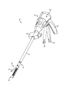
[0048] FIGS. 1 and 2 depict a surgical cutting and fastening instrument 10
according to
various embodiments of the present invention. The illustrated embodiment is an
endoscopic
surgical instrument 10 and in general, the embodiments of the instrument 10
described herein
are endoscopic surgical cutting and fastening instruments. It should be noted,
however, that
according to other embodiments of the present invention, the instrument 10 may
be a non-
endoscopic surgical cutting instrument, such as a laproscopic instrument.
[0049] The surgical instrument 10 depicted in FIGS. 1 and 2 comprises a handle
6, a shaft 8,
and an articulating end effector 12 pivotally connected to the shaft 8 at an
articulation pivot
14. An articulation control 16 may be provided adjacent to the handle 6 to
effect rotation of
the end effector 12 about the articulation pivot 14. It will be appreciated
that various
embodiments may include a non-pivoting end effector, and therefore may not
have an
articulation pivot 14 or articulation control 16. Also, in the illustrated
embodiment, the end
effector 12 is configured to act as an endocutter for clamping, severing and
stapling tissue,
although, in other embodiments, different types of end effectors may be used,
such as end
effectors for other types of surgical devices, such as graspers, cutters,
staplers, clip appliers,
access devices, drug/gene therapy devices, ultrasound, RF or laser devices,
etc.
[0050] The handle 6 of the instrument 10 may include a closure trigger 18 and
a firing
trigger 20 for actuating the end effector 12. It will be appreciated that
instruments having end
effectors directed to different surgical tasks may have different numbers or
types of triggers or
other suitable controls for operating the end effector 12. The end effector 12
is shown
separated from the handle 6 by a preferably elongate shaft 8. In one
embodiment, a clinician
or operator of the instrument 10 may articulate the end effector 12 relative
to the shaft 8 by
utilizing the articulation control 16, as described in more detail in U.S.
Patent No. 7,670,334,
entitled "Surgical Instrument Having An Articulating End Effector," by
Geoffrey C. Hueil et
al.
CA 2806423 2017-12-07
CA 02806423 2013-01-23
WO 2012/015795 PCT/US2011/045313
100511 The end effector 12 includes in this exatnple, among other things, an
elongated
channel 22 configured to operably support a staple cartridge 34 therein and a
pivotally
translatable clamping member, such as an anvil 24, which are maintained at a
spacing that
assures effective stapling and severing of tissue clamped in the end effector
12. The handle 6
includes a pistol grip 26 toward which a closure trigger 18 is pivotally drawn
by the clinician
to cause clamping or closing of the anvil 24 towards the elongated channel 22
of the end
effector 12 to thereby clamp tissue positioned between the anvil 24 and
elongated channel 22.
The firing trigger 20 is farther outboard of the closure trigger 18. Once the
closure trigger 18
is locked in the closure position as further described below, the firing
trigger 20 may rotate
slightly toward the pistol grip 26 so that it can be reached by the operator
using one hand.
Then the operator may pivotally draw the firing trigger 20 toward the pistol
grip 26 to cause
the stapling and severing of clamped tissue in the end effector 12. In other
embodiments,
different types of clamping members besides the anvil 24 could be used, such
as, for example,
an opposing:jaw, etc.
100521 The closure trigger 18 may be actuated first. Once the clinician is
satisfied with the
positioning of the end effector 12, the clinician may draw back the closure
trigger 18 to its
fully closed, locked position proximate to the pistol grip 26. The firing
trigger 20 may then be
actuated. The firing trigger 20 returns to the open position (shown in FIGS. 1
and 2) when the
clinician removes pressure, as described more fully below. A release button on
the handle 6,
when depressed may release the locked closure trigger 18. The release button
may be
implemented in various forms such as, for example, slide release button 160
shown in FIG.
16, and/or button 172 shown in FIG. 17.
100531 FIGS. 3-6 show embodiments of a rotary-driven end effector 12 and shaft
8
according to various embodiments. FIG. 3 is an exploded view of the end
effector 12
according to various embodiments. As shown in the illustrated embodiment, the
end effector
12 may include, in addition to the previously-mentioned channel 22 and anvil
24, a cutting
instrument 32, a sled 33, a staple cartridge 34 that is removably seated in
the channel 22, and
a helical screw shaft 36. The cutting instrument 32 may be, for example, a
knife. As used
herein with respect to at least one embodiment, the term "actuator" may refer
to the knife
11
and/or sled. The anvil 24 may be pivotably opened and closed at pivot pins 25
connected to
the proximate end of the channel 22. The anvil 24 may also include a tab 27 at
its proximate
end that is inserted into a component of the mechanical closure system
(described further
below) to open and close the anvil 24. When the closure trigger 18 is
actuated, that is, drawn
in by a user of the instrument 10, the anvil 24 may pivot about the pivot pins
25 into the
clamped or closed position. If clamping of the end effector 12 is
satisfactory, the operator
may actuate the firing trigger 20, which, as explained in more detail below,
causes the knife
32 and sled 33 to travel longitudinally along the channel 22, thereby cutting
tissue clamped
within the end effector 12. The movement of the sled 33 along the channel 22
causes the
staples (not shown) of the staple cartridge 34 to be driven through the
severed tissue and
against the closed anvil 24, which turns the staples to fasten the severed
tissue. In various
embodiments, the sled 33 may be an integral component of the cartridge 34.
U.S. Patent No.
6,978,921, entitled "Surgical Stapling Instrument Incorporating an E-beam
Firing
Mechanism" to Shelton, IV et al., provides more details about such two-stroke
cutting and
fastening instruments. The sled 33 may be part of the cartridge 34, such that
when the knife
32 retracts following the cutting operation, the sled 33 does not retract.
[0054] FIGS. 4 and 5 are exploded views and FIG. 6 is a side view of the end
effector 12
and shaft 8 according to various embodiments. As shown in the illustrated
embodiment, the
shaft 8 may include a proximate closure tube 40 and a distal closure tube 42
pivotably linked
by a pivot link 44. The distal closure tube 42 includes an opcning 45 into
which the tab 27 on
the anvil 24 is inserted in order to open and close the anvil 24, as further
described below.
Disposed inside the closure tubes 40, 42 may be a proximate spine tube 46.
Disposed inside
the proximate spine tube 46 may be a main rotational (or proximate) drive
shaft 48 that
communicates with a secondary (or distal) drive shaft 50 via a bevel gear
assembly 52. The
secondary drive shaft 50 is connected to a drive gear 54 that engages a
proximate drive gear
56 of the helical screw shaft 36. The vertical bevel gear 52b may sit and
pivot in an opening
57 in the distal end of the proximate spine tube 46. A distal spine tube 58
may be used to
enclose the secondary drive shaft 50 and the drive gears 54, 56. Collectively,
the main drive
12
CA 2806423 2017-12-07
CA 02806423 2013-01-23
WO 2012/015795 PCT/US2011/045313
shaft 48, the secondary drive shaft 50, and the articulation assembly (e.g.,
the bevel gear
assembly 52a-c) are sometimes referred to herein as the "main drive shaft
assembly."
100551 A bearing 38, positioned at a distal end of the staple channel 22,
receives the helical
drive screw 36, allowing the helical drive screw 36 to freely rotate with
respect to the channel
22. The helical screw shaft 36 may interface a threaded opening (not shown) of
the knife 32
such that rotation of the shaft 36 causes the knife 32 to translate distally
or proximately
(depending on the direction of the rotation) through the staple channel 22.
Accordingly, when
the main drive shaft 48 is caused to rotate upon application of an actuation
motion to the
firing trigger 20 (as explained in more detail below), the bevel gear assembly
52a-c causes the
secondary drive shaft 50 to rotate, which in turn, because of the engagement
of the drive gears
54, 56, causes the helical screw shaft 36 to rotate, which causes the knife
driving member 32
to travel longitudinally along the channel 22 to cut any tissue clamped within
the end effector
12. The sled 33 may be made of, for example, plastic, and may have a sloped
distal surface.
As the sled 33 traverses the channel 22, the sloped forward surface may push
up or drive the
staples in the staple cartridge through the clamped tissue and against the
anvil 24. The anvil
24 forms or turns the staples, thereby stapling the severed tissue. When the
knife 32 is
retracted, the knife 32 and sled 33 may become disengaged, thereby leaving the
sled 33 at the
distal end of the channel 22.
100561 FIGS. 7-10 illustrate an exemplary embodiment of a motor-driven
endocutter, and in
particular the handle thereof, that provides user-feedback regarding the
deployment and
loading force of the cutting instrument 32 in the end effector 12. In
addition, the embodiment
may use power provided by the user in retracting the firing trigger 20 to
power the device (a
so-called "power assist" mode). The embodiment may be used with the rotary
driven end
effector 12 and shaft 8 embodiments described above. As shown in the
illustrated
embodiment, the handle 6 includes exterior lower side pieces 59, 60 and
exterior upper side
pieces 61, 62 that fit together to form, in general, the exterior of the
handle 6. In various
embodiments, the rotary driven end effector may be powered by a motor 65 that
is disposed in
an upper portion of the pistol grip portion 26 of the handle and powered by a
power source 64.
The power source 64 may cotnprise a battery or a supply of alternating
current. In a preferred
13
CA 02806423 2013-01-23
WO 2012/015795 PCT/US2011/045313
embodiment, the power source 64 comprises a Li ion battery that is supported
in the pistol
grip portion 26 of the handle 6. According to various embodiments, the motor
65 may be a
DC brushed driving motor having a maximum rotation of, approximately, 5000
RPM. The
motor 65 may drive a 90 degree bevel gear assembly 66 comprising a first bevel
gear 68 and a
second bevel gear 70. The bevel gear assembly 66 may drive a planetary gear
assembly 72.
The planetary gear assembly 72 may include a pinion gear 74 connected to a
drive shaft 76.
The pinion gear 74 may drive a mating ring gear 78 that drives a helical gear
drum 80 via a
drive shaft 82. A ring 84 may be threaded on the helical gear drum 80. Thus,
when the motor
65 rotates, the ring 84 is caused to travel along the helical gear drum 80 by
means of the
interposed bevel gear assembly 66, planetary gear assembly 72 and ring gear
78.
[0057] The handle 6 may also include a run motor switch 110 (see FIG. 10) in
communication with the firing trigger 20 to receive an actuation motion from
the firing trigger
20 when the firing trigger has been drawn in (or "closed") toward the pistol
grip portion 26 of
the handle 6 by the operator to thereby actuate the cutting/stapling operation
by the end
effector 12. The run motor switch 110 may be a proportional sensor such as,
for example, a
rheostat or variable resistor. When the firing trigger 20 is drawn in, the run
motor switch 110
permits current to flow from the power source 64 to the motor 65. When the run
motor switch
110 is a variable resistor or the like, the rotation of the motor 65 may be
generally
proportional to the amount of movement of the firing trigger 20. That is, if
the operator only
draws or closes the firing trigger 20 in a small amount, the rotation of the
motor 65 is
relatively low. When the firing trigger 20 is fully drawn in (or in the fully
closed position),
the rotation of the motor 65 is at its maximum. In other words, the harder the
user pulls on
the firing trigger 20, the more voltage is applied to the motor 65, causing
greater rates of
rotation.
[0058] The handle 6 may include a middle handle piece 104 adjacent to the
upper portion of
the firing trigger 20. The handle 6 may also include a bias spring 112 that is
connected
between posts on the middle handle piece 104 and the firing trigger 20. The
bias spring 112
may bias the firing trigger 20 to its fully open position. In that way, when
the operator
releases the firing trigger 20, the bias spring 112 will pull the firing
trigger 20 to its open
14
CA 02806423 2013-01-23
WO 2012/015795 PCT/US2011/045313
position, thereby deactivating the run motor switch 110 to stop rotation of
the motor 65.
Moreover, by virtue of the bias spring 112, any time a user closes the firing
trigger 20, the
user will experience resistance to the closing operation, thereby providing
the user with
feedback as to the amount of rotation exerted by the motor 65. Further, the
operator could
stop retracting the firing trigger 20 to thereby deactivate the run motor
switch 110 and stop
the motor 65. As such, the user may stop the deployment of the end effector
12, thereby
providing a measure of control of the cutting/fastening operation to the
operator.
100591 The distal end of the helical gear drum 80 includes a distal drive
shaft 120 that drives
a ring gear 122, which mates with a pinion gear 124. The pinion gear 124 is
connected to the
main drive shaft 48 of the main drive shaft assembly. In that way, rotation of
the motor 65
causes the main drive shaft assembly to rotate, which causes actuation of the
end effector 12,
as described above.
[0060] The ring 84 threaded on the helical gear drum 80 may include a post 86
that is
disposed within a slot 88 of a slotted arm 90. The slotted arm 90 has an
opening 92 its
opposite end 94 that receives a pivot pin 96 that is connected between the
handle exterior side
pieces 59, 60. The pivot pin 96 is also disposed through an opening 100 in the
firing trigger
20 and an opening 102 in the middle handle piece 104.
[0061] In addition, the handle 6 may include a reverse motor switch (or end-of-
stroke
switch) 130 and a stop motor (or beginning-of-stroke) switch 142. In various
embodiments,
the reverse motor switch 130 may be a limit switch located at the distal end
of the helical gear
drum 80 such that the ring 84 threaded on the helical gear drum 80 contacts
and trips the
reverse motor switch 130 when the ring 84 reaches the distal end of the
helical gear drum 80.
The reverse motor switch 130, when activated, sends a signal (i.e., permits
current to flow) to
the motor 65 to reverse its rotation direction, thereby withdrawing the knife
32 of the end
effector 12 following the cutting operation.
[0062] The stop motor switch 142 may be, for example, a normally-closed limit
switch. In
various embodiments, it may be located at the proximate end of the helical
gear drum 80 so
CA 02806423 2013-01-23
WO 2012/015795 PCT/US2011/045313
that the ring 84 trips the switch 142 when the ring 84 reaches the proximate
end of the helical
gear drum 80.
[0063] In operation, when an operator of the instrument 10 applies an
actuation motion to
the firing trigger 20, the run motor switch 110 detects the deployment of the
firing trigger 20
and sends a signal (i.e., permits current to flow) to the motor 65 to cause
forward rotation of
the motor 65, for example, at a rate proportional to how hard the operator
pulls back the firing
trigger 20. The forward rotation of the motor 65 in turn causes the ring gear
78 at the distal
end of the planetary gear assembly 72 to rotate, thereby causing the helical
gear drum 80 to
rotate, causing the ring 84 threaded on the helical gear drum 80 to travel
distally along the
helical gear drum 80. The rotation of the helical gear drum 80 also drives the
main drive shaft
assembly as described above, which in turn causes deployment of the knife 32
in the end
effector 12. That is, the knife 32 and sled 33 are caused to distally traverse
the channel 22
longitudinally, thereby cutting tissue clamped in the end effector 12. Also,
the stapling
operation of the end effector 12 is caused to happen in embodiments where a
stapling-type
end effector 12 is used.
[0064] By the time the cutting/stapling operation of the end effector 12 is
complete, the ring
84 on the helical gear drum 80 will have reached the distal end of the helical
gear drum 80,
thereby causing the reverse motor switch 130 to be activated, which sends a
signal (i.e.,
permits current to flow) to the motor 65 to cause the motor 65 to reverse its
rotation. This in
turn causes the knife 32 to retract, and also causes the ring 84 on the
helical gear drum 80 to
move back to the proximate end of the helical gear drum 80.
[0065] The middle handle piece 104 includes a backside shoulder 106 that
engages the
slotted arm 90 as best shown in FIGS. 8 and 9. The middle handle piece 104
also has a
forward motion stop 107 that engages the firing trigger 20. The movement of
the slotted arm
90 is controlled, as explained above, by rotation of the motor 65. When the
slotted arm 90
rotates counter clockwise as the ring 84 travels from the proximate end of the
helical gear
drum 80 to the distal end, the middle handle piece 104 will be free to rotate
counter
clockwise. Thus, as the user draws in the firing trigger 20, the firing
trigger 20 will engage
the forward motion stop 107 of the middle handle piece 104, causing the middle
handle piece
16
CA 02806423 2013-01-23
WO 2012/015795 PCT/US2011/045313
104 to rotate counter clockwise. Due to the backside shoulder 106 engaging the
slotted arm
90, however, the middle handle piece 104 will only be able to rotate counter
clockwise as far
as the slotted arm 90 permits. In that way, if the motor 65 should stop
rotating for some
reason, the slotted arm 90 will stop rotating, and the user will not be able
to further draw in
the firing trigger 20 because the middle handle piece 104 will not be free to
rotate counter
clockwise due to the slotted arm 90.
100661 FIGS. 10A and 10B illustrate two states of a variable switches or
sensors that may be
used as the run motor switch 110 according to various embodiments of the
present invention.
The run motor switch 110 may include a face portion 280, a first electrode (A)
282, a second
electrode (B) 284, and a compressible dielectric material 286 between the
electrodes 282, 284,
such as, for example, an electroactive polymer (EAP). The run motor switch 110
may be
positioned such that the face portion 280 contacts the firing trigger 20 when
retracted.
Accordingly, when the firing trigger 20 is retracted, the dielectric material
286 is compressed,
as shown in FIG. 10B, such that the electrodes 282, 284 are closer together.
Since the distance
"b" between the electrodes 282, 284 is directly related to the impedance
between the
electrodes 282, 284, the greater the distance the more impedance, and the
closer the distance
the less impedance. In that way, the amount that the dielectric 286 is
compressed due to
retraction of the firing trigger 20 (denoted as force "F" in FIG. 10B) is
proportional to the
impedance between the electrodes 282, 284, which can be used to proportionally
control the
motor 65.
100671 Components of an exemplary closure system for closing (or clamping) the
anvil 24
of the end effector 12 by retracting the closure trigger 18 are also shown in
FIGS. 7-10. In the
illustrated embodiment, the closure system includes a yoke 250 connected to
the closure
trigger 18 by a pivot pin 251 inserted through aligned openings in both the
closure trigger 18
and the yoke 250. A pivot pin 252, about which the closure trigger 18 pivots,
is inserted
through another opening in the closure trigger 18 which is offset from where
the pin 251 is
inserted through the closure trigger 18. Thus, retraction of the closure
trigger 18 causes the
upper part of the closure trigger 18, to which the yoke 250 is attached via
the pin 251, to
rotate counterclockwise. The distal end of the yoke 250 is connected, via a
pin 254, to a first
17
CA 02806423 2013-01-23
WO 2012/015795 PCT/US2011/045313
closure bracket 256. The first closure bracket 256 connects to a second
closure bracket 258.
Collectively, the closure brackets 256, 258 define an opening in which the
proximate end of
the proximate closure tube 40 (see FIG. 4) is seated and held such that
longitudinal movement
of the closure brackets 256, 258 causes longitudinal motion by the proximate
closure tube 40.
The instrument 10 also includes a closure rod 260 disposed inside the
proximate closure tube
40. The closure rod 260 may include a window 261 into which a post 263 on one
of the
handle exterior pieces, such as exterior lower side piece 59 in the
illustrated embodiment, is
disposed to fixedly connect the closure rod 260 to the handle 6. In that way,
the proximate
closure tube 40 is capable of moving longitudinally relative to the closure
rod 260. The
closure rod 260 may also include a distal collar 267 that fits into a cavity
269 in proximate
spine tube 46 and is retained therein by a cap 271 (see FIG. 4).
[0068] In operation, when the yoke 250 rotates due to retraction of the
closure trigger 18,
the closure brackets 256, 258 cause the proximate closure tube 40 to move
distally (i.e., away
from the handle end of the instrument 10), which causes the distal closure
tube 42 to move
distally, which causes the anvil 24 to rotate about the pivot pins 25 into the
clamped or closed
position. When the closure trigger 18 is unlocked from the locked position,
the proximate
closure tube 40 is caused to slide proximately, which causes the distal
closure tube 42 to slide
proximately, which, by virtue of the tab 27 being inserted in the window 45 of
the distal
closure tube 42, causes the anvil 24 to pivot about the pivot pins 25 into the
open or
unclamped position. In that way, by retracting and locking the closure trigger
18, an operator
may clamp tissue between the anvil 24 and channel 22, and may unclamp the
tissue following
the cutting/stapling operation by unlocking the closure trigger 20 from the
locked position.
[0069] FIG. 11 is a schematic diagram of a current control circuit of the
instrument 10
according to various embodiments of the present invention. When an operator
initially pulls in
the firing trigger 20 after locking the closure trigger 18, the run motor
switch 110 is activated,
allowing current to flow therethrough. If the normally-open reverse motor
sensor switch 130
is open (meaning the end of the end effector stroke has not been reached),
current will flow to
a single pole, double throw relay 132. Since the reverse motor sensor switch
130 is not
closed, the inductor 134 of the relay 132 will not be energized, so the relay
132 will be in its
18
CA 02806423 2013-01-23
WO 2012/015795 PCT/US2011/045313
non-energized state. The circuit also includes a cartridge lockout switch 136.
If the end
effector 12 includes a staple cartridge 34, the switch 136 will be in the
closed state, allowing
current to flow. Otherwise, if the end effector 12 does not include a staple
cartridge 34, the
switch 136 will be open, thereby preventing the battery 64 from powering the
motor 65.
[0070] When the staple cartridge 34 is present, the switch 136 is closed,
which energizes a
single pole, single throw relay 138. When the relay 138 is energized, current
flows through
the relay 136, through the variable resistor (run motor) switch 110, and to
the motor 65 via a
double pole, double throw relay 140, thereby powering the motor 65 and
allowing it to rotate
in the forward direction.
[0071] When the end effector 12 reaches the end of its stroke, the reverse
motor switch 130
will be activated, thereby closing the reverse motor switch 130 and energizing
the relay 134.
This causes the relay 134 to assume its energized state, which causes current
to bypass the
cartridge lockout switch 136 and variable resistor 110, and instead causes
current to flow to
both the normally-closed double pole, double throw relay 142 and back to the
motor 65, but in
a manner, via the relay 140, that causes the motor 65 to reverse its
rotational direction.
[0072] Because the stop motor switch 142 is nomally-closed, current will flow
back to the
relay 134 to keep it closed until the stop motor switch 142 opens. When the
knife 32 is fully
retracted, the stop motor switch 142 is activated, causing the stop motor
switch 142 to open,
thereby removing power from the motor 65.
[0073] In other embodiments, rather than a proportional-type switch 110, an on-
off type
sensor or switch could be used. In such embodiments, the rate of rotation of
the motor 65
would not be proportional to the force applied by the operator. Rather, the
motor 65 would
generally rotate at a constant rate. But the operator would still experience
force feedback
because the firing trigger 20 is geared into the gear drive train.
[0074] As indicated above, there are several steps within the function of a
stapler that
generally must be accomplished in an established order. For example, once the
closure
trigger is clamped, the firing cycle may be actuated. After the knife has been
fully deployed,
then retraction of the system is the next sequential step. With the inclusion
of a power source
19
other than the user (i.e. batteries or pneumatics) the ability to reduce user
initiated steps (and
therefore device complexity) the system itself, as was discussed above, can
begin to
accomplish these steps itself.
[0075] It may be desirable, however, for the user to intuitively be able to
delay, slow or stop
these otherwise "automatic" actuations. For example, the same actuation button
that would
allow for firing initiation in a tactile feedback device like the devices
disclosed in U.S. Patent
Application Serial No. 11/344,035, now U.S. Patent No. 7,422,139, could be
used to slow or
stop an automatic return system by the user depressing the button during the
retraction.
[0076] For example, FIGS. 12 and 13 illustrate another embodiment of the
present invention
wherein a retraction trigger 121 is supported on the firing trigger 20 for
travel therewith.
More specifically, the retraction trigger 121 is pivotally supported on firing
trigger pin 96 and
protrudes through a slot (not shown) in the firing trigger 20. A spring 125 is
attached between
a coupling portion 123 of the firing trigger 100 and a mounting portion 127 of
the retraction
trigger 121 to bias the retraction trigger 121 into an unactuated position. A
second, normally
-
closed, retraction switch 131 is mounted within the handle and is oriented
such that, as the
firing trigger 20 is moved between a fully actuated position to a fully
unactuated position, an
activation portion 129 of the retraction trigger 121 does not activate the
retraction switch 131.
However, the mounting portion 127 and activation portion 129 of the retraction
trigger 121
are so configured such that the activation portion 129 may be brought into
activation contact
with the retraction switch 131 by depressing the retraction trigger 121
towards the firing
trigger 20 regardless of where the firing trigger 20 is located during the
retraction process.
[0077] As was discussed above, when the end effector 12 reaches the end of its
stroke, the
end of stroke switch 130 will be activated. As shown in the example of FIG.
13, the retraction
switch 131 is in series with the end-of-stroke switch 130. Because the
retraction switch 131 is
normally closed, relay 134 will be energized when both switches 130, 131 are
closed. This
causes the relay 134 to assume its energized state, which causes current to
bypass the
cartridge lockout sensor 136 and variable resistor 110. Current to flows to
the double pole,
double throw relay 140 and to the motor 65, but in a manner, via the relay
140, that causes the
CA 2806423 2017-12-07
motor 65 to reverse its rotational direction. Because the beginning-of-stroke
switch 142 is
closed, current will flow back to the relay 134 to keep it closed until the
switch 142 opens.
When the knife 32 is fully retracted, the beginning-of-stroke switch 142 is
opened, thereby
removing power from the motor 65. If, however, the user wants to slow down the
retraction
process, the user may depress the retraction trigger 121 to activate the
variable resistance
portion 133 of the retraction switch 131. When the retraction trigger 121 is
not depressed, the
resistance of the variable resistance portion 133 is a minimum. When the
trigger 121 is
depressed, the resistance of the variable resistance portion 133 increases in
proportion to the
depressing force of the retraction trigger 121 to reduce the current to the
motor 65. Further
depression of the retraction trigger 121 will slow the retraction process
until the normally
closed contact 135 portion of the retraction switch 131 opens and stops the
current flow to the
motor 65. In various embodiments, once the user releases the retraction
trigger 121, the
spring 125 will move the retraction trigger 121 to an unactuated position and
the contact
portion 135 of switch 131 will return to the normally closed position and
thereby permit
current to flow again to the motor 65 to complete the retraction process.
[0078] The unique and novel features of the retraction switch and retraction
trigger
arrangements described above may also be employed in connection with the
various
embodiments disclosed in U.S. Patent Application Publication No. US
2010/007674 Al, and
U.S. Patent No. 7,422,139. For example, FIG. 14 shows another embodiment of a
current
control circuit embodiment of the present invention. When (i) the run motor
(or fire) switch
110 is closed (it is shown in an open state in FIG. 14), (ii) the safety
switch 240 is closed (it is
shown open in FIG. 14) indicating that the device safety is set, and (iii) the
normally-closed
lockout switch 242 is opened indicating that the instrument is not in a lock-
out condition,
current flows through the safety switch 240, through the lockout indicator 244
(which may be
a LED as shown in FIG. 14) to the motor 65. When the end of the cutting stroke
is reached,
the end-of-stroke or direction switch 130 is switched, reversing the direction
of the motor 65
(with the fire switch 110 also having been released). In this state, current
also flows through a
reverse direction indicator 246, such as an LED, providing a visual indication
that the motor
direction has been reversed.
21
CA 2806423 2017-12-07
[0079] As shown in FIG. 14, the circuit may also comprise a manual return
switch 248. The
operator may manually actuate this switch if the cutting instrument 32 has
only been partially
fired. Switching the manual return switch 248 causes the motor 65 to reverse
rotate, causing
the cutting instrument 32 to return to its original or home position. If, the
user desires to slow
down or stop the retraction process, the user depresses the retraction trigger
121 to activate
the variable resistance portion 133 of the retraction switch 131. When the
trigger 121 is
depressed, the resistance increases in portion to the depressing force to
reduce the current to
the motor 65. Further depression of the retraction trigger 121 will slow the
retraction process
until the normally closed contact 135 portion of the retraction switch 131
opens and stops the
current flow to the motor 65. In various embodiments, once the user releases
the retraction
trigger 121, the spring 125 will move the retraction trigger 121 to an
unactuated position and
the contact portion 135 of switch 131 will return to the normally closed
position and thereby
permit current to flow again to the motor 65 to complete the retraction
process.
[0080] Additional configurations for motorized surgical instruments are
disclosed in
published U.S. Patent Application Publication No. US 2010/0076474 A 1,
entitled "Motor-
Driven Surgical Cutting Instrument". For example, FIG. 15 is a schematic
diagram of another
current control circuit according to various embodiments of the present
invention. In various
embodiments, the motor control circuit may include one of more integrated
circuits (lCs),
such as, for example, a processor, memory, microcontroller, time circuits,
etc. In other
embodiments, the motor control circuit may not comprise any ICs. Such a non-IC
current
control circuit may be advantageous because it is often difficult,
complicated, and expensive
to sterilize a surgical instrument including ICs.
100811 When an operator initially applies an actuation motion to the firing
trigger 20 after
locking the closure trigger 18, the run motor switch 110 is activated (or
closed), allowing
current to flow therethrough. If the normally open reverse motor sensor switch
130 is open
(meaning the end of the end effector stroke has not been reached), current
will flow to a single
pole, double throw relay 132. When the reverse motor sensor switch 130 is not
closed, a coil
134 of the relay 132 will not be energized, so the relay 132 will be in its de-
energized state.
22
CA 2806423 2017-12-07
CA 02806423 2013-01-23
WO 2012/015795 PCT/US2011/045313
[0082] As shown in FIG. 15, the circuit may also include a resistive element
144 and a
switch 146 connected in parallel, with the paralleled elements connected in
series with the
relay 132. The resistive element 144 and the switch 146 are also connected to
the power
source 64. The switch 146 may be controlled by a control circuit 148 that is
responsive to the
cutting instrument position sensor 150. According to various embodiments, the
control circuit
148 may open the switch 146 when the cutting instrument 32 is (i) very near to
the beginning
of its stroke and (ii) very near to the end of its stroke. For example, the
control circuit may
open the switch when the cutting instrument 32 is (i) 0.001 inches from the
beginning point of
its stroke and (ii) 0.001 inches from the end of its stroke, as determined by
the cutting
instrument position sensor 150. With the switch 146 open, current flows
through the resistive
element 144, and then through the relay 132, the relay 138, the run motor
sensor switch 110,
to the motor 65. Current flowing through the resistive element 144 reduces the
magnitude of
the current delivered to the motor 65, thereby reducing the power delivered by
the motor 65.
Thus, when the cutting instrument 32 is (i) very near to the beginning of its
stroke or (ii) very
near to the end of its stroke, the power delivered by the motor 65 is reduced.
Conversely, once
the cutting instrument 32 moves sufficiently far from its beginning point or
end of stroke
point, the control circuit 148 may close the switch 146, thereby shorting the
resistive element
144, thereby increasing the current to the motor 65, thereby increasing the
power delivered by
the motor.
[0083] According to various embodiments, the current control circuit further
includes
lockout sensor switches 136a-d collectively defining an interlock circuit 137
through which
current from the relay 132, when de-energized, passes in order for electrical
operation of the
motor 65 to be initiated. Each lockout sensor switch 136a-d may be configured
to maintain an
open (i.e., non-conductive) switch state or a closed (i.e., conductive) switch
state responsive
to the presence or absence, respectively, of a corresponding condition. Any of
the
corresponding conditions, if present when the instrument 10 is fired, may
result in an
unsatisfactory cutting and stapling operation and/or damage to the instrument
10. Conditions
to which the lockout sensor switches 136a-d may respond include, for example,
(a) the
absence of the staple cartridge 34 in the channel 22, (b) the presence of a
spent (e.g.,
previously fired) staple cartridge 34 in the channel 22, and (c) an open (or
otherwise
23
CA 02806423 2013-01-23
WO 2012/015795 PCT/US2011/045313
insufficiently closed) position of the anvil 24 with respect to the channel
22. Other conditions
to which the lockout sensor switches 136a-d may respond, such as component
wear, may be
inferred based upon an accutnulated nutnber of firing operations produced by
the instrument
10. Accordingly, in various embodiments, if any of these conditions exists,
the corresponding
lockout sensor switches 136a-d maintain an open switch state, thus preventing
passage of the
current necessary to initiate operation of the motor 65. Passage of current by
the lockout
sensors 136a-d is allowed, in various embodiments, only after all of the
conditions have been
remedied. It will be appreciated that the above-described conditions are
provided by way of
example only, and that additional lockout sensor switches for responding to
other conditions
detrimental to operation of the instrument 10 may be provided. It will
similarly be
appreciated that for embodiments in which one or more of the above-described
conditions
may not exist or are of no concern, the number of lockout sensor switches may
be fewer than
that depicted.
[0084] As shown in FIG. 15, the lockout sensor switch 136a may be implemented
using a
normally open switch configuration such that a closed switch state is
maintained when the
staple cartridge 34 is in a position corresponding to its proper receipt by
the channel 22.
When the staple cartridge 34 is not installed in the channel 22, or is
installed improperly (e.g.,
mis-aligned), the lockout sensor switch 136a maintains an open switch state.
Lockout sensor
switch 136b may be implemented using a normally open switch configuration such
that a
closed switch state is maintained only when an unspent staple cartridge 34
(i.e., a staple
cartridge 34 having a sled 33 in the unfired position) is present in the
channel 22. The
presence of a spent staple cartridge 34 in the channel 22 causes the lockout
sensor switch
136b to maintain an open switch state. Lockout sensor switch 136c may bc
implemented
using a normally open switch configuration such that a closed switch state is
maintained when
the anvil 24 is in a closed position with respect to the channel 22. The
lockout sensor switch
136c may be controlled in accordance with a time delay feature wherein a
closed switch state
is maintained only after the anvil 24 is in the closed position for a pre-
determined period of
time.
24
CA 02806423 2013-01-23
WO 2012/015795 PCT/US2011/045313
100851 Lockout sensor switch 136d may be implemented using a normally closed
switch
configuration such that a closed switch state is maintained only when an
accumulated number
of firings produced by the instrument 10 is less than a pre-determined number.
The lockout
sensor switch 136d may be in communication with a counter 139 configured for
maintaining a
count representative of the accumulated number of firing operations performed
by the
instrument 10, comparing the count to the pre-determined number, and
controlling the switch
state of the lockout sensor switch 136d based upon the comparison. Although
shown
separately in FIG. 15, it will be appreciated that counter 139 may be integral
with the lockout
sensor switch 136d so as to form a common device. Preferably, the counter 139
is
implemented as an electronic device having an input for incrementing the
maintained count
based upon the transition of a discrete electrical signal provided thereto. It
will be appreciated
that a mechanical counter configured for maintaining the count based upon a
mechanical input
(e.g., retraction of the firing trigger 20) may be used instead. When
implemented as an
electronic device, any discrete signal present in the electrical circuit that
transitions once for
each firing operation may be utilized for the counter 139 input. As shown in
FIG. 15, for
example, the discrete electrical signal resulting from actuation of the end-of-
stroke sensor 130
may be utilized. The counter 139 may control the switch state of lockout
sensor switch 136d
such that a closed switch state is maintained when the maintained count is
less than a pre-
determined number stored within the counter 139. When the maintained count is
equal to the
pre-determined number, the counter 139 causes the lockout sensor switch 136d
to maintain an
open switch state, thus preventing the passage of current therethrough. It
will be appreciated
that the pre-determined number stored by the counter 139 may be selectively
adjusted as
required. According to various embodiments, the counter 304 may be in
communication with
an external display (not shown), such as an LCD display, integral to the
instrument 10 for
indicating to a user either the maintained count or the difference between the
pre-determined
number and the maintained count.
100861 According to various embodiments, the interlock circuit 137 may
comprise one or
more indicators visible to the user of the instrument 10 for displaying a
status of at least one
of the lockout sensor switches 136a-d. More details regarding such indicators
may be found in
published U.S. Patent Application Publication No. 2007/0175956, entitled
"Electronic
Lockouts and Surgical Instrument Including Same". This application also
includes example
mounting arrangements and configurations for the lockout sensor switches 136a-
d.
[0087] In the illustrated embodiment, when the lockout sensor switches 136a-d
collectively
maintain a closed switch state, a single pole, single throw relay 138 is
energized. When the
relay 138 is energized, current flows through the relay 138, through the run
motor switch
sensor 110, and to the motor 65 via a double pole, double throw relay 140,
thereby powering
the motor 65, allowing it to rotate in the forward direction. According to
various
embodiments, because the output of the relay 138, once energized, maintains
the relay 138 in
an energized state until relay 132 is energized, the interlock circuit 137
will not function to
prevent operation of the motor 165 once initiated, even if one or more of the
interlock sensor
switches 136a-d subsequently maintains an open switch state. In other
embodiments,
however, it may be necessary or otherwise desirable to connect the interlock
circuit 137 and
the relay 138 such that one or more the lockout sensor switches 136a-d must
maintain a
closed switch state in order to sustain operation of the motor 165 once
initiated.
[0088] Rotation of the motor in the forward direction causes the ring to move
distally and
thereby de-actuate the stop motor sensor switch 142 in various embodiments.
Because the
switch 142 is normally closed, a solenoid 141 connected to the switch 142 may
be energized.
The solenoid 141 may be a conventional push-type solenoid that, when
energized, causes a
plunger (not shown) to be axially extended. Extension of the plunger may
operate to retain
the closure trigger 18 in the retracted position, thus preventing thc anvil 24
from opening
while a firing operation is in progress (i.e., while the switch 142 is not
actuated). Upon de-
cnergization of the solenoid 141, the plunger is retracted such that manual
release of the
closure trigger 18 is possible.
100891 When the actuation member portion reaches the distal most end of its
stroke, the
reverse motor switch 130 will be activated, thereby closing the switch 130 and
energizing the
relay 132. This causes the relay 132 to assume its energized state (not shown
in FIG. 11),
which causes current to bypass the interlock circuit 137 and= run motor sensor
switch 110, and
instead causes current to flow to both the normally-closed double pole, double
throw relay
140 and back to the motor 65, but in a manner, via the relay 140, that causes
the motor 65 to
reverse its rotational direction. Because the stop motor sensor switch 142 is
normally closed,
26
CA 2806423 2017-12-07
current will flow back to the relay 132 to keep it energized until the switch
142 opens. When
the knife 32 is fully retracted, the stop motor sensor switch 142 is
activated, causing the
switch 142 to open, thereby removing power from the motor 65, and de-
energizing the
solenoid 141.
[0090] In the embodiment depicted in FIG. 15, a normally closed retraction
switch 137 is
employed which interfaces with retraction trigger 121 (not shown in FIG. 15).
When
rctraction switch 137 is activated, it opcns to stop the flow of current to
the motor 65. In
alternative embodiments (FIG. 15A), the normally closed retraction switch 137
could be
replaced with a variable resistor 137' that interfaces with retraction trigger
121. In such
embodiment, when the retraction trigger 121 is not depressed, the resistance
of the variable
resistor is minimal to allow maximum current to flow to the motor 65. When
depressed the
resistance increases in proportion to the depressing force to reduce current
to the motor. Such
variable resistor may also be replaced with the retraction switch 131 as
described above (see
FIG. 15B).
[0091] Accidental actuation prevention for a powered endocutter: With the
introduction of
powered systems that no longer limit the device function to the force
capabilities of the user,
inadvertent initiation of the firing cycle may become a much more prevalent
issue. It will be
increasing ease to ''bump" the activation control and have the instrument
begin firing thereby
tripping thc lockout of the cartridgc or even "jamming" it on tissuc, as the
user is unaware it
has already begun firing. Various lockout arrangements are disclosed in U.S.
Patent No.
7,644,848, entitled "Electronic Lockouts and Surgical Instrument Including
Same" to Swayze
et al. To eliminate this issue secondary unlock activator switches or buttons
could be used to
unlock the firing mechanism. This is much the same as the two switch systems
used in the
power saw industry as well as the military to protect against accidental
actuation. The
secondary switch can either release the lock on the firing trigger or merely
energize the power
to the control.
[0092] As mentioned above, in using a two-stroke motorized instrument, the
operator first
pulls back and locks the closure trigger 18. FIGS. 16 and 17 show one
embodiment of a way
to lock the closure trigger 18 to the pistol grip portion 26 of the handle 6.
In the illustrated
27
CA 2806423 2017-12-07
embodiment, the pistol grip portion 26 includes a hook 150 that is biased to
rotate CCW about
a pivot point 151 by a torsion spring 152. Also, the closure trigger 18
includes a closure bar
154. As the operator draws in the closure trigger 18, the closure bar 154
engages a sloped
portion 156 of the hook 150, thereby rotating the hook 150 upward (or CW in
FIGS. 16 and
17) until the closure bar 154 completely passes the sloped portion 156 passes
into a recessed
notch 158 of the hook 150, which locks the closure trigger 18 in place. The
operator may
release the closure trigger 18 by pushing down on a slide button release 160
on the back or
opposite side of the pistol grip portion 26. Pushing down the slide button
release 160 rotates
the hook 150 CW such that the closure bar 154 is released from the recessed
notch 158. Other
arrangements for releasably locking the closure trigger 18 are disclosed in
U.S. Patent No.
7,422,139.
[0093] As can be seen in FIGS. 16 and 17, in various embodiments, a closure
lock switch
151 may be mounted in the hook 150 such that that is activated only when the
hook 150 is
latched in place. However, the closure lock switch 151 may be mounted in the
pistol grip
portion 26 for activation by the closure trigger 18 when the closure trigger
18 is locked in
position. In still other alternative embodiments, the closure lock switch 151
is mounted to the
end effector such that it is activated only when the anvil or other movable
portion is in the
"closed" position. Regardless of the specific location of the closure lock
switch 151, in
various embodiments, the closure lock switch is a normally open switch that
will be closed
upon locking of the closure trigger 18 or otherwise manipulating the end
effector to a "closed"
position.
[0094] FIG. 18 is a schematic diagram of an electrical circuit of the
instrument 10 according
to various embodiments of the present invention illustrating the use of the
closure lock switch
151. As can be seen in that Figure, current will not be permitted to flow from
the battery 64
to the motor 65 even if a cartridge is present unless the closure lock switch
151 is closed.
Thus, the motor 65 cannot be operated unless the closure trigger is in the
locked closed
position which also reflects that the end effector is in the closed state.
28
CA 2806423 2017-12-07
[0095] Various embodiments may further include a start switch 153 that must be
activated
by the surgeon before current will be permitted to flow from the battery 64 to
the other circuit
components and ultimately to the motor 65. Start switch 153 is normally open
and may be
located at a convenient location on the handle 6. See FIG. I. Thus, in these
embodiments,
even if the end effector contains a cartridge and the closure trigger 18 is
locked in a closed
position, current will not be permitted to flow to the motor 65 until the
start switch 153 is
closed by the surgeon. In alternative embodiments, the start switch 153 may
comprise a
mechanical switch that prevents the firing trigger 20 from being physically
rotated toward the
pistol grip portion unless the switch 153 is moved to an actuated position.
[0096] Active adjustable staple height for a powered endocutter: Staple height
that is
adjustable to the tissue thickness and type has been pursued for many years.
Most recently,
U.S. Patent Application Serial No. 11/231,456, filed September 21, 2005, now
U.S. Patent
No. 7,407,078 and U.S. Patent Application Serial No. 11/540,735, filed
September 29, 2006,
now U.S. Patent No. 7,467,740, generally involve a flexible coupling member or
supports that
would allow the gap of the instrument to enlarge with loads induced by thicker
tissue in the
device. This "passive" variable staple height allows the thickness of the
tissue to create larger
staple forms.
[0097] With the introduction of a power source within the instrument this
allows for the use
of electricity to change the height of an internal element within the dynamic
coupling element
with would change the height of the staple "actively" by the surgeon or
instrument setting the
desired height. This internal element could be a shape memory material and the
electricity
changes its temperature and therefore allows it to change its physical height
due to preset
configuration. Another viable method would be the inclusion of an electro-
active polymer
(EAP) that through the introduction of an electric field allows it to change
its height and
width. Yet a third embodiment would be to utilize a traditional linear
electrical stepper
29
CA 2806423 2017-12-07
CA 02806423 2013-01-23
WO 2012/015795 PCT/US2011/045313
element that can ratchet a small adjustable screw element within the coupling
beam that
would adjust its height.
[0098] More specifically and with reference to FIGS. 19 and 20, an end
effector 12 of
various embodiments of the present invention is shown in cross-section with
the anvil 24 in a
closed or clamped position. As can be seen, the cutting instrument or knife 32
has a lower
actuator portion 37 that has a threaded sleeve or nut portion 37' that is
configured to
threadably engage the helical screw shaft 36. In addition, a fin 39 protrudes
laterally from
each lateral side of the nut portion 37 to confront corresponding slide
portions 23 of the
channel 22. As can also be seen in FIG. 19, the knife 32 has an upper actuator
portion 41 that
is sized to be received within a longitudinal T-shaped slot 43 in the anvil
24. As can be seen
in FIG. 19, a pair of upper retainer pins 41' protrude laterally from each
side of the upper
actuator portion 41 of the knife 32. Each upper retainer pin 41' is configured
to extend into a
corresponding portion of the T-shaped slot 43 provided in the anvil 24. Thus,
as the knife 32
is driven distally through the end effector 12, the fins 39 and the retainer
pins 41' serve to
limit the amount of space between the anvil 24 and the cartridge 34 to a
maximum amount of
predetermined space.
[0099] Various embodiments of the present invention are provided with means
for adjusting
the amount of space between the anvil 24 and the cartridge 34 installed within
the channel 22.
For example, in some embodiments, each fin 39 supports a sled contact 45 for
sliding contact
with corresponding electrical contacts 47 that are mounted within each slide
portion 23 of the
channel 22. The electrical contacts 47 are elongated and extend within the
channel 22 so that
the sled contacts 45 are always on contact with their corresponding electrical
contact 47 as the
knife 32 is driven within the channel 22. Electrical contacts 47 are connected
to the power
source or battery 64 and are configured to receive current therefrom when the
motor 65 is
powered to drive the knife 32 distally. Also in certain embodiments, an
electrically
responsive height adjustment member 49 is mounted to each retainer pin 41' as
shown in FIG.
19. The height adjustment members 49 are electrically coupled to the sled
contacts 45 to
receive electrical current therefrom. In various embodiments, the height
adjustment members
49 may comprise shape memory material that, when electrified, changes its
physical height
CA 02806423 2013-01-23
WO 2012/015795 PCT/US2011/045313
due to a preset configuration. Thus, depending upon the amount of current
received, the
height adjust member members 49 may expand and force the anvil 24 towards the
cartridge
34 to thereby reduce the amount of space therebetween. The amount that such
material is
proportional to the amount of current received and is known. A control circuit
(not shown)
may be employed to control the amount of expansion and hence the amount of
space between
the anvil 24 and the cartridge 34. In other embodiments, the height adjustment
material
comprises an electro-active polymer (EAP) that is retained within a pocket in
the pin 41 or is
otherwise attached thereto.
101001 FIG. 21 illustrates another embodiment that is similar to the
embodiment depicted in
FIG. 19. However, in this embodiment, the height adjustment members 49 are
mounted in the
anvil 24 and receive current from the power source through conductors attached
directly
thereto. Thus, in this embodiment, the contacts 43 and 45 as described above
are not needed.
[0101] FIG. 22 illustrates an alternative knife assembly 32' that is
substantially identical to
the knife assembly 32 described above, except that the retainer pins 41' are
mounted to a
separate upper actuator portion 302 that is selectively movable in a vertical
direction "VD"
relative to a lower portion 300 of the knife assembly 32'. A second motor 304
may be
mounted to the lower portion 300 and have a lead screw 306 that threadably
engages a nut
portion 308 of the upper retainer portion 302. The upper retainer portion has
a "T"-shaped
tongue portion 310 that slidably extends into a correspondingly shaped slot
312 in the lower
portion 300 to prevent rotation of the upper retainer portion 302 relative to
the lower retainer
portion 300 while permitting the upper retainer portion 302 to move vertically
relative thereto.
Thus, the distance between the upper and lower retainer portions 302, 300 may
be adjusted by
powering the second motor 304. Accordingly, if the surgeon wants to reduce the
amount of
space between the anvil 24 and the cartridge 34, second motor 304 is powered
to rotate in a
first direction to draw the upper retainer portion 302 towards the lower
retainer portion 300.
If however, the surgeon desires to increase the amount of space between the
anvil 24 and the
cartridge 34, the second motor 304 is rotated in an opposite direction.
[0102] Various embodiments of the present invention include end-effector
illumination
methods and methods for illuminating the surgical site when employing a
powered
31
endocutter. Currently when the end-effector is in or near its deployment
position it is
sometimes difficult for the surgeon to visualize the treatment site as there
are shadows cast by
adjacent structures as well as the end-effector may even be behind another
structure entirely.
FIG. 23 illustrates in general form, a distal end 402 of a surgical stapler
400 of various
embodiments of the present invention which includes an anvil 404, a cartridge
body 406, and
channel 408. As seen from that Figure, an additional light source 410 may be
positioned on
the end of the cartridge body 406 to illuminate tissue 401. This light source
410 could be any
combination of practical means that convert electrical energy to light
including but not limited
to semiconductor (such as LED), a conventional incandescent or filament bulb,
electroluminescent or laser that may be powered from a battery supported in
the instrument
handle or in other embodiments, powered by alternating current. Such
arrangements would
allow the surgeon to not only light up the treatment site directly, they could
allow for
backlighting of structures to see the internal components like vasculature and
facilitate the use
of a laser pointer through a traditional scope to point out areas of interest
to others.
[0103] In various embodiments, one or more contacts 420 are provided on the
back of the
cartridge body 406 that are configured to engage contacts 422 within the
channel 408. See
FIG. 24. This would allow the surgeon to energize the light 410 as needed by
energizing
contact set via a switch positioned on the handle 430. This switch could even
have variable
intensity as the one described in could control the actuation speed of the
main, device. Other
lighting arrangements for lighting the end of an anvil attached to a circular
surgical stapler are
disclosed in U.S. Patent Application Publication No. US 2010/0096435 A 1 ,
entitled "Surgical
Stapling Instrument With Apparatus For Providing Anvil Position Feedback",
Published April
22, 2010.
[0104] U.S. Patent Application Publication No. 2007/0175949 A1, entitled
"Surgical Instrument Having a Feedback System", Published August 2, 2007,
further
discloses in Figures 45-47 of that Publication output displays that could show
among
other this position feedback of the end-effector, lockout status, number of
firings
etc. This would minimize one of the more difficult issues for the user, which
is
the identification of the status of a device, especially the lockout
32
CA 2806423 2017-12-07
CA 02806423 2013-01-23
WO 2012/015795 PCT/US2011/045313
status of the device without actuating the device. An additional feedback that
would be
helpful for the user would be immediate feedback as to the status of the
cartridge when it is
loaded. As in the above application it could be rolled up into the lockout
indication on the
handle 430. An indicator 432 (such as an LED, glass bulb, LCD, sonic
enunciator, vibrator,
etc.) could solely be associated with the status of a cartridge lockout means
or mechanism
such that it providing this information to the surgeon. This LED could be
located on the
handle 430. See FIG. 26. Alternatively an indicator 434 could be located near
the distal end
402 which would provide immediate information to the surgeon and loader if the
cartridge is
"good to go" or not. See FIG. 25. This can be accomplished with a switch or
set of contacts
associated directly with the mechanical lockout. The switch or contacts
complete a circuit
such that the indicator provides appropriate information. This completed
contact set could be
through a conductive element within the sled (part 33 in U.S. Patent
Application Publication
No. US 2007/0175958) and the two contacts could be in the proximal position of
the channel
(part 22). Another way to detect lockout status is indirectly through
instrument status
(example I: loaded cartridge and no attempt to fire would indicate lockout is
not engaged;
example 2: fired instrument and no new cartridge installed would indicate
lockout is engaged;
etc.). Another embodiment would be to place the LED or visual indication cue
on the
cartridge itself. When the cartridge is snapped into place it creates a
contact that supplies the
cartridge with power. Should the cartridge be fired not only does the
mechanical lockout stop
the advancement of the knife the cartridge circuit light up the LED on the
cartridge informing
the surgeon on the scope monitor that the cartridge is locked out. This could
be further
expanded by placing a small battery or other charge accumulator within the
cartridge itself to
eliminate the need for a power connection to the main device. Also the
cartridge circuit could
be set to light the lockout light whenever the device is closed to inform the
user there is a
spent cartridge in the device.
101051 Indication feedback for powered articulation and cartridge color:
Indicating the type
of cartridge installed (color) and angle of articulation is considered useful
to the surgeon. The
indication of articulation angle could be indicated in several ways including
numerically or
graphically as in an arc of LEDs. The location of this indication could be on
the handle in a
convenient location or on the shaft of the device just proximal to the end-
effector. The end-
33
CA 02806423 2013-01-23
WO 2012/015795 PCT/US2011/045313
effector feedback could be passive or active. The active would light up
additional LEDs to
show the angle. The passive could just show a half pie lighted up so the
surgeon could intuit
how articulated the end-effector is. As we further explore the surgical
procedures it becomes
more and more obvious that the surgeon's eyes need to be on the surgical site
not on the
handle of the instrument. We also begin to understand the surgeon's need for
complete status
feedback from the device. Articulation angle could be illuminated as part of
the articulation
joint itself. With lights, LEDs, etc. denoting the differing angle or even a
small LCD denoting
angle in degrees. This would allow the surgeon to have some feedback on the
angle off of
straight so he/she can easily navigate back to this angle after removal and
reinsertion. Another
issue is "obvious" indication of what color cartridge is in the device. This
can be
accomplished by a color coded light array on either the end-effector or the
cartridge. This
information could also be transmitted back to the handle to display a
"redundant" display to
assure there is minimal confusion as to what cartridge is in the jaws. Another
improvement
could include a small leaf spring contact connected to the proximal deck of
the cartridge that
indicates if a minimum tissue pressure has been achieved within the jaws. This
minimum
pressure would at the very least indicate if a thick tissue cartridge is being
used in thin tissue
applications, as it would not light if insufficient tissue pressure on the
deck were present.
[0106] There is a possible need of a method for the introduction of non-
sterile battery packs
(possibly with the electronics integral to the battery pack if programmable
logic becomes a
key customer need). A patent already exists within the orthopedic drill
industry for the
insertion of a non-sterile battery pack within a separately sterilized re-
useable device. This
innovation is intended to improve that concept by utilizing the disposable
device sterile
packaging to protect the sterility of the instrument during the insertion of
the non-sterile
battery pack. A further improvement would be the inclusion of a "hatch" door
designed
within the instrument and closable after the pack has been inserted but before
the device is
removed from the final sterile packaging. This hatch would then "contain" the
non-sterile
battery that could contaminate the sterile surgical field. The method here
would be to include
an additional layer of packaging that would have a perforated area that the
battery could be
pushed through, either rupturing the extra layer and allowing the battery
through or going
with the electrode set of the battery only to be ruptured by the exposable pin
tips of the battery
34
CA 02806423 2013-01-23
WO 2012/015795 PCT/US2011/045313
at complete insertion. An alternative of this would be to have the internal
terminals of the gun
(deep inside the battery protection cavity) rupture the sterile barrier and
seat within pinholes
in the battery pack. The hatch could then be closed through the sterile pack
sealing the
system. The gun could then be handed into the sterile field normally as any
sterile device
could.
101071 Position Locator Embodiments / Linear encoder and load control of motor
parameters: U.S. Patents 6,646,307 and 6,716,223 disclose the mechanisms for
the
measurement of rotation and related torque to control motor parameters and
optimizing of
those parameters based on identification of end-effector configurations and
loading. U.S.
Patent Application Publication No. 2007/0175958 shows a method through the use
of a
threaded length of the primary shaft in Figures 8-13 how this type of linear
motion control
could be used to control the trigger location. The same type of method could
be used for
electronic linear control methods. The end-effector could identify its length
and type
mechanically by depressing at least one spring biased plunger, which could
identify to the
handle the type, and length it would allow the motor to run. The motor
rotation could be
converted from rotary motion to linear rack or cable motion, which could then
be used to
adjust motor voltage, current, and speed to affect the desired linear motion
of the control
slide. The control slide could then be directly coupled to the knife drive
motion. This control
slide could have discrete or continuous "stop" locations that the plunger
identifier marks as
the max "go to" linear displacement before retraction
101081 Identification of modular reloads with linear drive: A useful feature
for a surgical
instrument is the ability to identify which end-effector has been attached to
the instrument. In
the case of a powered surgical stapler, several different types of end-
effectors could be
attached. Additionally, a type of end-effector may have at least one function
and/or feature
that is selectively utilized or enabled. Disclosed are means for identifying
which end-effector
is attached. Note that the "type" of end-effector referenced below is not
limited to mechanical,
pneumatic or hydraulically coupled end-effectors. The instrument may take
different actions,
adjust operating parameters, indicate available functions etc. as a result of
detecting this end
effector.
CA 02806423 2013-01-23
WO 2012/015795 PCT/US2011/045313
[0109] The end-effector has an electrical connection that is made when it is
attached to the
instrument. The instrument communicates with the end-effector and reads at
least one of
several types of signals. A switch position or contact position indicates
which type of end-
effector is present. A passive element is measured for impedance and the
result indicates
which type of end-effector is present.
[0110] The end-effector has a radio frequency link to the instrument and data
is transferred
in at least one direction between the end-effector and the instrument.
[0111] The end-effector has an acoustic link to the instrument and data is
transferred in at
least one direction between the end-effector and the instrument.
[0112] The end-effector has an optical link to the instrument and data is
transferred in at
least one direction between the end-effector and the instrument.
101131 The end-effector has mechanical link that engages elements (such as
switches or
contacts) in the instrument that identify it and thereby data is transferred
in at least one
direction between the end-effector and the instrument.
[0114] While the present invention has been illustrated by description of
several
embodiments and while the illustrative embodiments have been described in
considerable
detail, it is not the intention of the applicant to restrict or in any way
limit the scope of the
appended claims to such detail. Additional advantages and modifications may
readily appear
to those skilled in the art.
[0115] For example, although the embodiments described above have advantages
for an
endoscopically employed surgical severing and stapling instrument 10, a
similar embodiments
may be used in other clinical procedures. It is generally accepted that
endoscopic procedures
are more common than laparoscopic procedures. Accordingly, the present
invention has been
discussed in terms of endoscopic procedures and apparatus. However, use herein
of terms
such as "endoscopic", should not be construed to limit the present invention
to a surgical
instrument for use only in conjunction with an endoscopic tube (i.e., trocar).
On the contrary,
it is believed that the present invention may find use in any procedure where
access is limited
36
to a small incision, including but not limited to laparoscopic procedures, as
well as open
procedures.
[0116] The disclosure as explicitly set forth herein supersedes any
conflicting material
referenced.
[0117] While this invention has been described as having exemplary designs,
the present
invention may be further modified within the spirit and scope of the
disclosure. This
application is therefore intended to cover any variations, uses, or
adaptations of thc invention
using its general principles. Further, this application is intended to cover
such departures from
the present disclosure as come within known or customary practice in the art
to which this
invention pertains.
37
CA 2806423 2017-12-07