Note: Descriptions are shown in the official language in which they were submitted.
CA 02806623 2013-01-25
WO 2012/062245 PCT/DE2011/001517
Inflatable Umbrella
The present invention relates to an inflatable umbrella.
Conventional umbrellas and in particular rain umbrellas are devices that are
in general relatively
unwieldy and are often awkward to use. They are particularly inconvenient when
not in use, i.e.
when sunny or rainy weather has either not yet begun or has already stopped.
Particularly due
to the fact that they are not easily portable, they are often left behind or
forgotten. As a result,
they are also often not brought along, for example when sun or rain is not
likely. If, for example,
rain does then occur contrary to expectations, people are largely unprotected
or attempt to
protect themselves from the rain in a makeshift way by covering their heads
with objects such
as a purse or items of clothing such as a jacket or the like. This takes its
toll on these objects
and items of clothing. In addition, such makeshift solutions only afford
insufficient protection.
This basic problem has been known for a long time, leading to the development
of partially
collapsible umbrellas, which have also been known for a long time and which in
the closed state
take up significantly less space than conventional umbrellas, but are still
relatively large and
unwieldy. It is in fact possible for them to fit into a purse or the like that
is carried. However,
when doing so, the considerable weight of these umbrellas makes their presence
annoying.
Also, when no purse is to be carried, there is usually no practical way to
carry these umbrellas.
The above-described problem is becoming even more critical due to the fact
that the change in
worldwide climate conditions could result in the fact that local weather
conditions change more
quickly from one extreme to another. As a result, weather conditions and in
particular the
probability of rain, can change significantly within a few hours or even a
shorter time frame. It is
therefore necessary when out of doors to be able to protect oneself from the
possibility of a
sudden onset of rain at any moment.
It is clear from the documents of the prior art that one direction toward
which improvements in
umbrella usability strive is to reduce their awkwardness, i.e. the number and
or size of awkward
parts in umbrellas. The awkwardness of conventional umbrellas is in particular
due to the
handle, the central holding rod, and the radial struts that stretch open the
umbrella fabric. The
CA 02806623 2013-01-25
WO 2012/062245 2 PCT/DE2011/001517
aim of modifications is therefore necessarily to replace these elements with
other elements that
are roughly functionally equivalent.
A large number of prior publications have therefore already proposed embodying
an umbrella in
the form of an inflatable umbrella, which is inflated for use and otherwise,
can be practically
transported in the collapsed state. A gas-filled envelope replaces the
umbrella fabric that is
usually stretched open by metallic structures, thus providing the necessary
rigidity.
The publication DE 10 2006 009 262 Al describes an umbrella that has an
inflatable envelope
that assumes the shape of a dome when inflated. The dome can be held over the
head of a
user for protection. On the inside of the inflatable envelope, a chemical
reaction can produce a
gaseous substance that serves to inflate the envelope.
In principle, a very high pressure in an inflatable envelope can also achieve
a very high rigidity
of the envelope. Since the inflatable envelope cannot be very thick so that it
is not too heavy
and does not take up too much space when in a collapsed state, however, it is
not possible for
the pressure to be limitlessly high. Consequently, in the inflatable umbrellas
that have been
disclosed up to now, the problem has been that in an inflated state, they do
not have the
required stability to resist powerful, externally acting forces such as forces
generated by heavy
wind or rain.
The object of the present invention is to create an improved inflatable
umbrella that is more
stable in an inflated state and is better able to resist external forces than
previously known the
umbrellas.
This object can be attained by an inflatable umbrella as recited in claim 1.
Advantageous
modifications and embodiments are the subject of dependent claims.
In a first embodiment, an umbrella has an inflatable envelope composed of a
flexible material. In
an inflated state, this envelope is comprised of at least the following
elements: a central holding
element, at least three umbrella strut elements extending away from the
central holding
element, and at least one umbrella surface element stretched open by the
umbrella strut
elements. The central holding element and each umbrella strut element are
supported against
each other at their respective contact point.
CA 02806623 2013-01-25
WO 2012/062245 3 PCT/DE2011/001517
The support of the central holding element and the umbrella strut elements
against one another
on the one hand centers, vertically aligns, and stabilizes the central holding
element. On the
other hand, it produces a stable alignment of the umbrella strut elements. The
statics are
automatically produced by self-locking structures. On the whole, this achieves
greater stability
and resistance to external forces such as wind forces or forces generated by
the impact of rain.
In a second embodiment, two respective adjoining umbrella strut elements are
supported
against each other at their respective contact point. The additional support
of umbrella strut
elements against one another can achieve an additional stabilization of the
umbrella and in
particular, an increased resistance to laterally acting forces such as wind
forces.
In a third embodiment, an imaginary center axis of an umbrella strut element
intersects with an
imaginary center axis of an umbrella strut element adjoining it on a first
side, outside of an
imaginary center axis of the central holding element. Consequently, each
umbrella strut element
extends next to and laterally offset from the central holding element. The
ends of the umbrella
strut elements oriented toward the central holding element are thus grouped
around the central
holding element in a way that centers, vertically aligns, and stabilizes it,
thus on the whole
achieving a greater stability of the umbrella.
In a fourth embodiment, an imaginary center axis of an umbrella strut element
and an imaginary
center axis of an umbrella strut element adjoining it on a first side are skew
to each other and a
span of extremely short length between the imaginary center axis of the
umbrella strut element
and the imaginary center axis of the umbrella strut element adjoining it on
the first side does not
intersect with an imaginary center axis of the central holding element.
Consequently, each
umbrella strut element extends next to and laterally offset from the central
holding element. The
ends of the umbrella strut elements oriented toward the central holding
element are thus
grouped around the central holding element in a way that centers, vertically
aligns, and
stabilizes it, thus on the whole achieving a greater stability of the
umbrella.
In a fifth embodiment, an umbrella strut element and an umbrella strut element
adjoining it on a
first side are supported against each other at a contact point, which is
located at an end of the
umbrella strut element oriented toward the umbrella strut element adjoining it
on the first side
while the umbrella strut element and an umbrella strut element adjoining it on
a second side are
CA 02806623 2013-01-25
WO 2012/062245 4 PCT/DE2011/001517
supported against each other at a contact point, which is located at an end of
the umbrella strut
element adjoining the second side oriented toward the umbrella strut element.
Consequently,
the umbrella strut elements are supported against each other so that they are
aligned in a stable
fashion. An increased resistance to laterally acting forces is achieved.
In a sixth embodiment, a cross-sectional area of the central holding element
increases in a
penultimate section of the central holding element before the umbrella strut
elements and
decreases in a final section of the central holding element before the
umbrella strut elements
and a cross-sectional area of each respective umbrella strut element increases
in a penultimate
section of the respective umbrella strut element before the central holding
element and
decreases in a final section of the umbrella strut element before the central
holding element. In
the regions with the enlarged cross-sectional area, the central holding
element and the umbrella
strut elements are more rigid and stable.
In a seventh embodiment, an end of the central holding element oriented toward
the umbrella
strut elements is embodied as essentially pyramid-shaped, a cross-sectional
area of the central
holding element forms a base of the pyramid, and the respective contact point
of the central
holding element and the respective umbrella strut element is situated on a
respective side
surface of the pyramid. As a result, the end of the central holding element
oriented toward the
umbrella strut elements is embodied with a number of oblique surfaces that
corresponds to the
number of umbrella strut elements at which the central holding element and the
umbrella strut
elements rest against one another in a stable fashion.
In an eighth embodiment, an end of each respective umbrella strut element
oriented toward the
central holding element is embodied as essentially pyramid-shaped; a cross-
sectional area of
the umbrella strut element forms a base of the pyramid, the respective contact
point of the
respective umbrella strut element and the central holding element is situated
on a first side
surface of the pyramid, a contact point of the respective umbrella strut
element and an umbrella
strut element adjoining it on a first side is situated on a second side
surface of the pyramid, and
a contact point of the respective umbrella strut element and an umbrella strut
element adjoining
it on a second side is situated on a third side surface of the pyramid. As a
result, at the end of a
respective umbrella strut element oriented toward the central holding element,
there are a
number of oblique surfaces that on the one hand, serve to support the umbrella
strut element
and the central holding element against each other and on the other hand,
serve to support the
CA 02806623 2013-01-25
WO 2012/062245 5 PCT/DE2011/001517
umbrella strut element and the adjoining umbrella strut elements against each
other. On the
whole, this achieves a high stability of the umbrella.
In a ninth embodiment, the umbrella has a compressible material and a valve
and through
compression of the compressible material, a gaseous substance for the
inflation can be
aspirated via the valve and conveyed into the interior of the inflatable
envelope. By repeatedly
compressing the compressible material, the umbrella can be quickly inflated
with the gaseous
substance. If after being manufactured, the umbrella is collapsed down under a
negative
pressure or vacuum, the volume of the compressible material can be minimized,
thus achieving
a small size of the collapsed umbrella.
In a tenth embodiment based on the ninth embodiment, the compressible material
is enclosed
by an envelope composed of a flexible material whose one end is connected to
the valve and
whose other end forms an inner tube valve; the gaseous substance can be
conveyed into the
interior of the inflatable envelope via the inner tube valve. The inner tube
valve is controlled by a
pressure on the interior of the umbrella or inflatable envelope, thus making
it possible to pump
up the umbrella in cooperation with the valve.
In an eleventh embodiment based on the ninth embodiment, the compressible
material is a
material with a foam structure that can be successively compressed by an
increasing pressure
in the inflatable envelope so that a pumping power that can be achieved with
the compressible
material decreases and excessive pressure does not build up in the inflatable
envelope. The
interior pressure being built up achieves a desired reduction in the pumping
power, which
automatically prevents a maximum permissible pressure from being exceeded.
In a twelfth embodiment based on the ninth embodiment, the compressible
material is situated
in a handle of the central holding element with a changed cross-sectional area
and can be
compressed through manual pumping actions executed by a user. This makes
optimal use of
the shape of the hollow of a hand and achieves a high pumping power.
In a thirteenth embodiment, at least two chemical substances are situated
separately from each
other in the inflatable envelope; when they are brought into contact with each
other, a chemical
reaction can be triggered, by means of which a gaseous substance can be
generated for the
inflation. This permits an automatic inflation through simple means.
CA 02806623 2013-01-25
WO 2012/062245 6 PCT/DE2011/001517
In a fourteenth embodiment, the umbrella has a telescoping handle and before
an inflation, the
inflatable envelope is contained inside the telescoping handle and the
inflation can be produced
by pumping actions of the telescoping handle. The packing of the inflatable
envelope in the
telescoping handle before an inflation can reduce the amount of space taken up
by the umbrella
when not in use.
In a fifteenth embodiment, the inflatable envelope has at least one valve and
can be inflated
and/or deflated via the valve. A user can inflate the umbrella by mouth at any
time and can also
empty it again.
Exemplary embodiments of the present invention are described by way of example
below with
reference to the drawings.
In the drawings,
Fig. 1 is a perspective view (obliquely from below) of an umbrella according
to a first
exemplary embodiment in an inflated state;
Fig. 2 is a cross-sectional view of the umbrella according to the first
exemplary embodiment
in the inflated state;
Fig. 3 is an enlarged view (obliquely from below) of a central region of the
umbrella
according to the first exemplary embodiment in the inflated state;
Fig. 4 is a top view of the umbrella according to the first exemplary
embodiment in the
inflated state;
Fig. 5 is a perspective view (obliquely from below) of an umbrella according
to a second
exemplary embodiment in an inflated state;
Fig. 6 is a top view of the umbrella according to the second exemplary
embodiment in the
inflated state;
CA 02806623 2013-01-25
WO 2012/062245 7 PCT/DE2011/001517
Fig. 7 is a cross-sectional view of a first alternative inflating system for
the umbrella
according to the first or second exemplary embodiment;
Fig. 8 is a cross-sectional view of a second alternative inflating system for
the umbrella
according to the first or second exemplary embodiment; and
Fig. 9 is a cross-sectional view of a third alternative inflating system for
the umbrella
according to the first or second exemplary embodiment.
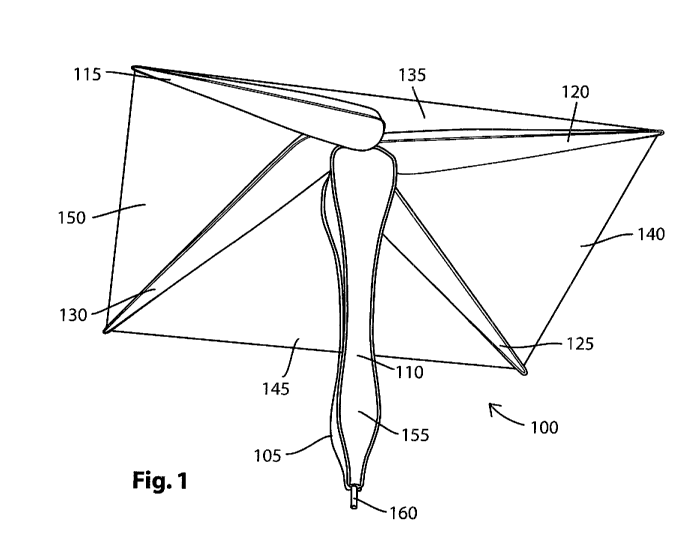
Fig. 1 is a perspective view (obliquely from below) of an umbrella 100
according to a first
exemplary embodiment in an inflated state. The umbrella has an inflatable
envelope 105. This
envelope is composed of a flexible material, e.g. a suitable plastic material
such as
polypropylene, polyethylene terephthalate (PET), or the like. Alternatively, a
suitable film
material, in particular balloon film, can be used. For example, this material
can be Heptax or
Mylar@, a biaxially oriented polyester film ("boPET") made of PET. Mytar
features a high
tensile strength, chemical, mechanical, and thermal stability, as well as
transparency. It is a
good electrical insulator and has a low water absorption. These properties are
advantageous for
the umbrella 100 according to the first exemplary embodiment.
In the umbrella 100 according to the first exemplary embodiment, in the
inflated state, the
inflatable envelope 105 forms a central holding element 110, four umbrella
strut elements 115,
120, 125, 130 extending away from the central holding element 110 and four
umbrella surface
elements 135, 140, 145, 150 spread open by the umbrella strut elements 115,
120, 125, 130.
Fig. 1 shows how the umbrella strut elements 115, 120, 125, 130 are grouped
around the
central holding element 110 and spread open the umbrella surface elements 135,
140, 145,
150. Fig. 1 also shows that the umbrella strut elements 115, 120, 125, 130 are
supported
against the central holding element 110 and vice versa. This is explained in
detail below.
As shown in Fig. 1 and also in Fig. 2, the central holding element 110 has a
changed cross-
sectional area in a region before an end of the central holding element 110
oriented away from
the umbrella strut elements 115, 120, 125, 130. To be more precise, an
ergonomically shaped
handle 155 is provided in this region, which is designed for a user's hand and
permits the user
to comfortably hold the umbrella 100. The larger cross-sectional area also
increases the rigidity
CA 02806623 2013-01-25
WO 2012/062245 8 PCT/DE2011/001517
and stability of the central holding element 110 in the region of the handle
155. A first valve 160
is situated at a lower end of the handle 155.
Fig. 2 shows a cross-sectional view of the umbrella 100 according to the first
exemplary
embodiment in the inflated state. The drawing shows that the central holding
element 110 and a
respective umbrella strut element 115, 125 are supported against each other at
their respective
contact point. The central holding element 110 functions as a pressure element
and the
respective umbrella strut element 115, 125 functions as a counterpart pressure
element and
vice versa. Fig. 2 shows this for the central holding element 110 and the
cross-sectionally
depicted umbrella strut element 115 by means of a pair of arrows 205, 210
pointing at each
other and shows this for the central holding element 110 and the cross-
sectionally depicted
umbrella strut element 125 by means of a pair of arrows 215, 220 pointing at
each other.
In other words, the central holding element 110 and each of the umbrella strut
elements 115,
120, 125, 130 are supported against each other. This achieves a vertical and
stable alignment
of the central holding element 110 and a stable alignment of the umbrella
strut elements 115,
120, 125, 130. In other words, the statics are automatically produced by self-
locking structures.
The vertical alignment of the central holding element 110 is indicated by an
arrow 225 in Fig. 2.
The umbrella strut elements 115, 120, 125, 130 spread open the umbrella
surface elements
135, 140, 145, 150. Each pair of adjoining umbrella strut elements spreads
open an interposed
umbrella surface element or the edges thereof. In Fig. 2, an arrow 230 with
two heads indicates
this for the umbrella strut element 115 situated on the left side and for an
adjoining umbrella
strut element 130, which is not visible in the cross-sectional view due to its
position behind the
central holding element 110. On the whole, the inflation of the umbrella
produces a spreading
force, which is symbolized in Fig. 2 by an arrow 235 with two heads.
The inflatable envelope 105 of the umbrella 100 shown in Fig. 2 is equipped
with the first valve
160 and a second valve 240. It can be inflated via the first valve 160 by
mouth or by means of
an external inflating device and can be deflated via the second valve 240. In
this case, the first
valve 160 can be a check valve. It is also possible, however, to use the same
valve 160 both for
inflating and deflating the inflatable envelope 105. For example, a simple
mouthpiece can be
provided with a closure. In addition, alternative inflating systems can be
used, some of which
are described further below.
CA 02806623 2013-01-25
WO 2012/062245 9 PCT/DE2011/001517
Fig. 3 is an enlarged view (obliquely from below) of a central region of the
umbrella 100
according to the first exemplary embodiment in the inflated state. The support
of the central
holding element 110 and the umbrella strut element 115 against each other at
their contact point
is illustrated in the drawing by means of two pairs of arrows 305, 310 and
315, 320 pointing at
each other while the support of the central holding element 110 and the
umbrella strut element
120 against each other at their contact point is illustrated in the drawing by
means of two pairs
of arrows 325, 330 and 335, 340 pointing at each other. A respective contact
point can also
extend, for example, over an area between the two pairs of arrows 305, 310 and
315, 320; and
325, 330 and 335, 340 and on both sides, as shown in Fig. 3.
In addition to the support of the central holding element 110 and a respective
umbrella strut
element against each other, two adjoining umbrella strut elements can also be
supported
against each other at their respective contact point. A respective umbrella
strut element and an
umbrella strut element adjoining it on a first side are supported against each
other at a contact
point, which is located at an end of the umbrella strut element oriented
toward an umbrella strut
element adjoining it on the first side, while the umbrella strut element and
an umbrella strut
element adjoining it on a second side are supported against each other at a
contact point, which
is located at an end ¨ oriented toward the umbrella strut element ¨ of the
umbrella strut element
adjoining the second side. This is visible in Fig. 3 and Fig. 4 as well, for
example for the
umbrella strut element 120, the umbrella strut element 125 adjoining it on a
first side, and the
umbrella strut element 115 adjoining it on a second side.
The support of adjoining umbrella strut elements against one another is more
pronounced the
more umbrella strut elements the umbrella 100 has and the more powerful the
forces are that
act on the umbrella 100 from the outside. The support of two adjoining
umbrella strut elements
against each other is shown for the two umbrella strut elements 115, 120 in
Fig. 3 by means of
a pair of arrows 345, 350 pointing at each other.
As a result, in comparison to previously known inflatable umbrellas, the
umbrella 100 according
to the first exemplary embodiment has a greater stability when in the inflated
state. This means
CA 02806623 2013-01-25
WO 2012/062245 10 PCT/DE2011/001517
that it is more resistant to external forces such as wind forces or forces
generated by the impact
of raindrops.
Fig. 4 is a top view of the umbrella 100 according to the first exemplary
embodiment in the
inflated state. This top view shows imaginary center axes 405, 410, 415, 420
of the umbrella
strut elements 115, 120, 125, 130 and the contact points or contact surfaces
425, 430, 435, 440
between the central holding element 110 and the umbrella strut elements 115,
120, 125, 130. It
is clear that an imaginary center axis of an umbrella strut element, e.g. the
imaginary center axis
405 of the umbrella strut element 115, intersects with an imaginary center
axis of an umbrella
strut element adjoining it on a first side, e.g. the imaginary center axis 410
of the umbrella strut
element 120õ outside of an imaginary center axis of the central holding
element 110 (which in
Fig. 4, extends in the middle of the cross-section of the central holding
element 110 and
perpendicular to the plane of the drawing, but is not explicitly depicted) and
the imaginary center
axis of the umbrella strut element and the imaginary center axis of the
umbrella strut element
adjoining it on the first side are skew to each other and a span of extremely
short length
between these two imaginary center axes does not intersect the imaginary
center axis of the
central holding element 110. As a result, ends of the umbrella strut elements
115, 120, 125, 130
oriented toward the central holding element 110 are grouped around the central
holding element
110 in a way that centers, vertically aligns, and stabilizes this central
holding element.
A cross-sectional area of the central holding element 110 increases in a
penultimate section of
the central holding element 110 before the umbrella strut elements 115, 120,
125, 130 and
decreases in a final section of the central holding element 110 before the
umbrella strut
elements 115, 120, 125, 130. As a result, at an end of the central holding
element 110 oriented
toward the umbrella strut elements 115, 120, 125, 130, a number of oblique
surfaces is formed,
which corresponds to the number of umbrella strut elements. In the umbrella
100 according to
the first exemplary embodiment, this number is four. A cross-sectional area of
a respective
umbrella strut element increases in a penultimate section of the umbrella
strut element before
the central holding element 110 and decreases in a final section of the
umbrella strut element
before the central holding element 110. As a result, at an end of the
respective umbrella strut
element oriented toward the central holding element 110, an oblique surface is
produced,
whose angle corresponds to an angle of the corresponding oblique surface of
the central
holding element 110. The angle here can vary, but must not be too flat in
order to prevent the
CA 02806623 2013-01-25
WO 2012/062245 11 PCT/DE2011/001517
umbrella surface from folding inside out, for example, when acted on by wind
forces. The central
holding element 110 and the umbrella strut elements 115, 120, 125, 130 are
supported against
one another by means of the oblique surfaces that correspond to each other.
The embodiment of the associated ends of the central holding element 110 and
umbrella strut
elements 115, 120, 125, 130 can therefore also be described as follows. The
end of the central
holding element 110 oriented toward the umbrella strut elements 115, 120, 125,
130 is
embodied as essentially pyramid-shaped and a cross-sectional area of the
central holding
element 110 constituting a base of the pyramid and a respective contact point
of the central
holding element 110 and a respective umbrella strut element, e.g. the contact
point 425 of the
central holding element 110 and the umbrella strut element 115, is situated on
a respective side
surface of the pyramid. The end of the respective umbrella strut element, i.e.
the umbrella strut
element 115, oriented toward the central holding element 110 is embodied as
essentially
pyramid-shaped; a cross-sectional area of the respective umbrella strut
element constitutes a
base of the pyramid; the respective contact point of the respective umbrella
strut element and
the central holding element, e.g. the contact point 425 of the umbrella strut
element 115 and the
central holding element 110, is situated on a first side surface of the
pyramid; a respective
contact point of the respective umbrella strut element and an umbrella strut
element adjoining it
on a first side, e.g. the umbrella strut element 120, is situated on a second
side surface of the
pyramid; and a contact point of the respective umbrella strut element and an
umbrella strut
element adjoining it on a second side, e.g. the umbrella strut element 130, is
situated on a third
side surface of the pyramid. In this case, angles of the corresponding side
surfaces of the
pyramid are not too flat and are selected so that they fit one another.
In other words, a reverse pyramid structure encloses the central holding
element 110
concentrically so that this central holding element is centered, vertically
aligned, and stabilized.
This gives the umbrella 100 the required stability.
The rigidity of the central holding element 110 is greater in a region with a
larger cross-sectional
area. This is calculated based on the Kessel formula according to which
tangential and axial
stresses in the inflatable envelope 105 are greater in the region with the
larger cross-sectional
area, which results in a greater rigidity and stability of the central holding
element 110 in this
region. The same is true for each of the umbrella strut elements 115, 120,
125, 130 in a
respective region with a larger cross-sectional area.
CA 02806623 2013-01-25
WO 2012/062245 12 PCT/DE2011/001517
Fig. 5 is a perspective view (obliquely from below) of an umbrella 500
according to a second
exemplary embodiment in an inflated state. The umbrella 500 according to the
second
exemplary embodiment differs from the umbrella 100 according to the first
exemplary
embodiment in that it has two more umbrella strut elements, i.e. is provided
with six umbrella
strut elements.
In the umbrella 500 according to the second exemplary embodiment, an
inflatable envelope 505
in the inflated state forms a central holding element 510, six umbrella strut
elements 515, 520,
525, 530, 535, 540 extending away from the central holding element 510, and
six umbrella
surface elements 545, 550, 555, 560, 565, 570 spread open by the umbrella
strut elements 515,
520, 525, 530, 535, 540. The central holding element 510 has a handle 575
whose lower end is
provided with a first valve 580. The above explanations regarding the umbrella
100 according to
the first exemplary embodiment also apply in analogous to the umbrella 500
according to the
second exemplary embodiment.
Fig. 6 is a top view of the umbrella 500 according to the second exemplary
embodiment in the
inflated state. This top view shows imaginary center axes 605, 610, 615, 620,
625, 630 of the
umbrella strut elements 515, 520, 525, 530, 535, 540 and contact points or
contact surfaces
635, 640, 645, 650, 655, 660 between the central holding element 510 and the
umbrella strut
elements 515, 520, 525, 530, 535, 540.
The above sections describe umbrellas 100, 500 respectively provided with four
and six
umbrella strut elements according to the first and second exemplary
embodiments. Naturally, it
is also possible to produce umbrellas with more or fewer umbrella strut
elements. In general, at
least three umbrella strut elements are required in order for the umbrella to
remain stable in the
inflated state. When there are only three umbrella strut elements, there are
therefore also only
three umbrella surface elements and the umbrella is triangular when viewed
from above. With a
number of umbrella strut elements totaling 12 or more, one the one hand, a
manufacture of the
umbrella is in fact too complicated sometimes and on the other hand, the
production is more
complex and therefore expensive the more umbrella strut elements are provided.
In principle,
however, the number of umbrella strut elements is unlimited at the top end.
CA 02806623 2013-01-25
WO 2012/062245 13 PCT/DE2011/001517
Fig. 7 is a cross-sectional view of a first alternative inflating system for
the umbrella 100 or 500
according to the first or second exemplary embodiment. In this case, the
central holding element
110 or 510 has a compressible material 705 and a valve 710 in a region before
its end oriented
away from its umbrella strut elements 115, 120, 125, 130 and 515, 520, 525,
530, 535, 540; the
compressible material 705 and the valve 710 can also be provided at another
location in the
umbrella 100 or 500. If after being manufactured, the umbrella 100 or 500 is
collapsed down
under a negative pressure or vacuum, the volume of the compressible material
705 can be
minimized, thus achieving a small size of the collapsed umbrella 100 or 500.
The compressible material 705 can be enclosed by an envelope 715 of flexible
material whose
lower end is connected to a valve 710 and whose upper end constitutes an inner
tube valve 720
that can be controlled by a pressure on the interior of the inflatable
envelope 105 or 505. The
valve 710 can be a check valve, e.g. a diaphragm valve, which can be composed
of a soft
diaphragm and a device that holds the diaphragm. Instead of the inner tube
valve 720, a
different type of valve can also be provided at the upper end of the envelope
715. For example,
a diaphragm valve can be used here as well.
By compressing the compressible material 705, a gaseous substance for the
inflation of the
inflatable envelope 105 or 505 can be aspirated via the valve 710 and conveyed
into the interior
of the inflatable envelope 105 or 505 via the inner tube valve 720. The
gaseous substance is
typically ambient air. Incoming air is conveyed through the valve 710 and
checked by it. This
process is indicated in Fig. 7 by two arrows 725, 730 that symbolize the
compression and two
arrows 735, 740 that symbolize the aspiration and the conveying of the air
into the interior of the
inflatable envelope 105 or 505 via the inner tube valve 720.
The compressible material 705 can be a material with a foam structure. For
example, it can be
normal foam. When a pressure in the inflatable envelope 105 or 505 increases,
this increasing
pressure gradually compresses the compressible material 705 further and
further. This
successive compression of the material due to the increasing pressure inside
the inflatable
envelope 105 or 505 gradually reduces a pumping power that can be achieved
with the
compressible material 705, thus making it impossible for excessive pressure to
be built up in the
inflatable envelope 105 or 505. In other words, the internal pressure in the
inflatable envelope
105 or 505 building up during the pumping-up procedure achieves a desired
reduction in the
CA 02806623 2013-01-25
WO 2012/062245 14 PCT/DE2011/001517
pumping power, which automatically prevents a maximum permissible pressure
from being
exceeded.
The compressible material 705 can be situated in the handle 155 or 575 of the
central holding
element 110 or 510 and can be compressed through manual pumping actions
executed by a
user. This enables optimal use to be made of the shape of the hollow of a
hand. The user can
therefore first pump up the umbrella 100 or 500 by repeatedly compressing the
handle 155 or
575 and after it is inflated, can hold the umbrella 100 or 500 by the handle
155 or 575. In this
connection, for both the pumping-up and for the subsequent holding, it is
advantageous if the
handle 155 or 575 is ergonomically shaped and fits well into the user's hand.
Fig. 8 is a cross-sectional view of a second alternative inflating system for
the umbrella 100 or
500 according to the first or second exemplary embodiment. In this case, the
umbrella 100 or
500 has a telescoping handle 800 with at least two segments. In the exemplary
embodiment of
the telescoping handle 800, which is shown in Fig. 8, there are three segments
805, 810, 815.
The telescoping handle 800 is provided with a valve 820 at its lower end.
By pumping actions of the telescoping handle 800, a gaseous substance for
inflating the
inflatable envelope 105 or 505 can be aspirated via the valve 820 and conveyed
to the interior
of the inflatable envelope 105 or 505. Before the inflation process, the
inflatable envelope 105 or
505 is contained inside the telescoping handle 800.
Fig. 9 is a cross-sectional view of a third alternative inflating system for
the umbrella 100 or 500
according to the first or second exemplary embodiment. In this case, at least
two chemical
substances are situated separately from each other in the inflatable envelope
105 or 505, which
produce a chemical reaction when brought into contact with each other. This
chemical reaction
generates a gaseous substance for inflating the inflatable envelope 105 or
505. The gaseous
substance disperses inside the inflatable envelope 105 or 505, thus inflating
the umbrella 100 or
500.
As is clear from Fig. 9, a first chemical substance 910 is provided in a
container 905 such as a
pouch composed of a flexible material. The first chemical substance 910 can
contain or be
composed of a liquid. The liquid can, for example, be an acid such as citric
acid, formic acid,
tartaric acid, malic acid, succinic acid, amido-sulfuric acid, or fumaric
acid. A second chemical
CA 02806623 2013-01-25
WO 2012/062245 15 PCT/DE2011/001517
substance 915 is situated next to the container 905. The second chemical
substance 915 can
contain or be composed of a solid; the solid can be embodied in the form of a
powder or
granulate. For example, the solid can be a sodium carbonate (soda) or
bicarbonate of soda
(baking soda).
Pressing in on the inflatable envelope 105 or 505 at a corresponding location
can compress the
container 905 in such a way that it bursts. As a result, the first chemical
substance 910 can
escape and come into contact with the second chemical substance 915. The
contact of the two
chemical substances can trigger a chemical reaction that generates a gaseous
substance for
the inflation. For example, the chemical reaction can generate gaseous carbon
dioxide.
The container 905 and the second chemical substance 915 can be enclosed by a
membrane
920. The membrane 920 ensures that after the container 905 bursts, the first
chemical
substance 910 comes into contact as precisely and as completely as possible
with the second
chemical substance 915. It prevents the first chemical substance 910 or the
second chemical
substance 915 from escaping into the interior of the inflatable envelope 105
or 505 outside the
membrane 920 and permits the gaseous substance generated by the chemical
reaction to pass
through.
Other systems that are not described in detail here can also be used in
addition to the inflating
systems described above. These can, for example, include only a cartridge or
capsule that
contains a gaseous substance for inflation. Possible gaseous substances for
this purpose
include, for example, carbon dioxide, nitrous oxide, nitrogen, or compressed
air.
The above sections describe examples of an umbrella in which a number of
umbrella surface
elements corresponds to a number of umbrella strut elements. It is also
possible, however, to
produce an umbrella with a smaller number of umbrella strut elements. For
example, only a
single umbrella surface element can be provided, which is spread open by all
of the umbrella
strut elements together, with each pair of adjoining umbrella strut elements
spreading open an
edge of the umbrella surface element situated between them.
In the umbrellas described above, the central holding element has an
ergonomically shaped
handle with a changed cross-sectional area in a region before an end of the
central holding
element oriented away from the umbrella strut elements. A handle of this kind,
however, is not
CA 02806623 2013-01-25
WO 2012/062245 16 PCT/DE2011/001517
required. An umbrella can also be produced with a central holding element
whose cross-section
is constant in a region before an end of the central holding element oriented
away from the
umbrella strut elements.
In conclusion, the present invention relates to an inflatable umbrella 100 or
500. The umbrella
100 or 500 has an inflatable envelope 105 or 505 composed of a flexible
material. In an inflated
state, this envelope forms at least the following elements: a central holding
element 110 or 510;
at least three umbrella strut elements 115, 120, 125, 130 or 515, 520, 525,
530, 535, 540
extending away from the central holding element; and at least one umbrella
surface element
135, 140, 145, 150 or 545, 550, 555, 560, 565, 570 stretched open by the
umbrella strut
elements. In this instance, the central holding element 110 or 510 and a
respective umbrella
strut element are supported against each other at their respective contact
point 425, 430, 435,
440 or 635, 640, 645, 650, 655, 660. In comparison to previously known
inflatable umbrellas,
the umbrella 100 or 500 has a greater stability and resistance to external
forces when in the
inflated state.