Note: Descriptions are shown in the official language in which they were submitted.
WO 2012/020058 CA 02806986 2013-01-29 PCT/EP2011/063778
1
An attachment for percussion drill tools
Field of the Invention
The present invention relates to an attachment for a fluid-operated percussion
drill tool.
The invention is particularly concerned with an attachment that may be used to
back-
hammer through a restriction in a drilled hole.
Background to the Invention
A typical down-the-hole hammer comprises an external cylinder or outer wear
sleeve,
within which is mounted an inner cylinder, this in turn engaging with a
backhead
assembly. The backhead assembly is connected to source of compressed fluid via
a drill
rod. A sliding reciprocating piston co-operates with the inner cylinder and
backhead
assembly such that when compressed air is supplied through the backhead
assembly, the
piston acts with percussive effect on a drill bit retained within a chuck on
the outer wear
sleeve.
In some drilling applications, the drilled hole may cave in, and debris from
the walls of
the hole may fall down on the hammer. Such debris often lodges at the
connection
between the backhead and the drill rod, because the drill rod diameter is
typically
smaller than the diameter of the hammer and causes a restriction which impedes
withdrawal of the hammer from the drilled hole. When this happens, the hammer
is
pulled back against the restriction. The hammer must be pulled with sufficient
force to
pull it past the restriction. However, where the restriction is closely
packed, it may not
be possible to pull the hammer through the restriction and in such cases, the
hammer
may be lost in the drilled hole.
In prior art systems, a back hammer, such as that produced by PG Drilling
Equipment
USA LLC, may be installed in the drill string above the drilled hole when
required.
There are a number of disadvantages associated with such a system. The first
is that the
back hammer is attached in the drill string at the joint nearest to the
restriction. The
back hammer is therefore positioned above the restriction and simply shakes
the drill
rod in an attempt to free it from the restriction. A further disadvantage is
that the
WO 2012/020058 CA 02806986 2013-01-29 PCT/EP2011/063778
2
system is always on, that is, once installed, the back hammer operates
regardless of
whether a restriction is encountered or not.
Another prior art system is described in US Patent No. 5,119,891 which
provides an
adaptor for drilling strings, the adaptor having a controllable air passage.
The adaptor
comprises a body mountable on the lower end of a drill string and a sleeve
rotatably
mounted on the body and longitudinally moveable relative thereto. In normal
drilling
operation, pressurized air from a central pressure line of the drill string is
directed via a
central bore in the body to a first chamber defined by the body and the sleeve
and
through to a second chamber defined by the body and the sleeve and to the air
intake of
the hammer or drill bit. When the adaptor is to be used to clear a restriction
above the
hammer, the rotation of the drill string is stopped and the sleeve moves down
relative to
the body, such that the pressurized air can exhaust through exhaust passages
above the
sleeve to clear the debris. The sleeve may also be provided with teeth at an
upper end
thereof and the drill string may be rotated to enable the teeth to cut through
the
obstruction in the drill hole.
The primary disadvantage of this system is that, once the system is opened to
allow air
to exhaust through the restriction, it cannot be closed unless the hammer is
placed back
on the hole bottom or there is sufficient friction with the hole wall to
encourage the
system to close when rotating in the correct direction. Air thus continues to
flush above
the sleeve even after the restriction has been cleared. A further disadvantage
is that the
primary mechanism for removal of the restriction is the air flushed from the
hammer. In
certain cases this may not be sufficient to clear debris from a drilled hole
to allow the
hammer to be withdrawn. Although cutting teeth are also provided, again, these
may
not be sufficient to clear the restriction. Yet another disadvantage is that
the helical
splines are difficult to manufacture.
It is therefore desirable to provide a system which allows a percussion drill
tool to be
withdrawn from a drilled hole where a restriction has occurred while avoiding
many of
the disadvantages of prior art systems. In particular, it is desirable to
provide a system
for back hammering through a restriction which is operable only when a
restriction is
WO 2012/020058 CA 02806986 2013-01-29 PCT/EP2011/063778
3
encountered. It is also desirable to provide a system which closes to prevent
flushing
once the restriction is cleared.
Summary of the Invention
According to an aspect of the present invention, there is provided an
attachment for a
fluid-operated percussion drill tool, the drill tool having a backhead
assembly for
attachment to a drill rod, comprising:
a shaft attachable to the backhead assembly, wherein the shaft comprises a
central bore in fluid communication with a pressure bore of the drill rod; and
a sleeve co-axially slidably mounted on the shaft, the sleeve comprising an
outer
shoulder at a rear end thereof; and
at least one rearwardly-directed exhaust passage;
such that pressurised air is supplied from the central bore of the shaft to
urge the
sleeve rearwards into a closed position in which air is prevented from
exhausting
through the exhaust passage; and
when a restriction is encountered at the shoulder, the sleeve moves forward to
an
open position in which air is permitted to exhaust through the exhaust passage
adjacent
the restriction.
The terms "rear" and "rearwardly" as used herein are intended to indicate a
direction
opposite to the normal drilling direction of the drill tool. For example,
where the drill
tool is a down-the-hole hammer, the rearward direction is an upward direction.
Conversely, the "forward" as used herein is intended to indicate a direction
which is the
same as the normal drilling direction of the drill tool. Where the drill tool
is a down-
the-hole hammer, the forward direction is an downward direction.
An advantage of the present invention is that, because the sleeve is urged
into the closed
position by the pressurised air supplied from the shaft, the back hammer
attachment
operates only when a restriction is encountered at the outer shoulder. Under
normal
operation conditions, the sleeve remains in the closed position and little or
no air is
exhausted at the sleeve. When a restriction is encountered, the sleeve moves
forward
against the air pressure allowing air to flush through the exhaust passage to
clear the
restriction. In this open position, air may be flushed at a rear end of the
sleeve. Once
WO 2012/020058 CA 02806986 2013-01-29 PCT/EP2011/063778
4
the restriction has been cleared, the air pressure acting on the sleeve urges
the sleeve
back to the closed position. Thus, air is only flushed through the exhaust
passage when
a restriction is to be cleared, ensuring that the air flow to the drill tool
is not
compromised.
In normal operation, the sleeve is biased towards the closed end position by
pressure
within the central bore and when a restriction is encountered, the biasing is
overcome to
force the sleeve into the open flushing position in which air is permitted to
exhaust
through the exhaust passage adjacent the restriction.
According to a preferred embodiment, the sleeve further comprises an inner
pressure
face and pressurised air is supplied from the central bore of the shaft to act
on the inner
pressure face to urge the sleeve into the closed position. A chamber may be
defined
between the shaft and the sleeve, wherein the inner pressure face defines a
rear end of
the chamber. Suitably, the inner pressure face is forward-facing. The chamber
may be
in selective fluid communication with the central bore of the shaft.
The sleeve may be urged rearwards by way of the pressurised air acting
directly or
indirectly on the inner pressure face.
In an embodiment, the attachment further comprises:
a piston, slidably mounted on the central shaft and arranged for reciprocal
movement within the chamber to impart a percussive force to the inner pressure
face of
the sleeve, wherein the percussive force is in a rearward direction, that is,
in the
opposition direction to the normal percussive force imparted by the tool.
An advantage of this arrangement is that a percussive force applied to the
inner pressure
face of the sleeve causes the outer shoulder of the sleeve to hammer through
the
restriction. Air is also flushed through the exhaust passage to assist in
clearing the
restriction. A further advantage of the present invention is that the sleeve
is maintained
in the closed position by air pressure until a restriction is encountered.
This means that
air is not flushed upwards through the drilled hole unless necessary due to a
restriction,
and the air flow to the drill tool is not compromised.
WO 2012/020058 CA 02806986 2013-01-29 PCT/EP2011/063778
5
Ideally, the piston is arranged in the chamber such that pressurised air
supplied from the
central bore acts on the piston to urge the piston against the inner pressure
face of the
sleeve.
The piston may comprise a plurality of ports therethrough and when the sleeve
moves to
the open position, air supplied from the central bore flows through at least
one port in
the piston to cause the reciprocal movement of the piston within the chamber.
Preferably, the piston comprises a first plurality of ports and a second
plurality of ports
therethrough and when the sleeve moves to the open position, the first and
second
pluralities of ports are alternately pressurized and exhausted to cause the
reciprocal
movement of the piston within the chamber.
The attachment may further comprise:
at least one air supply port in the shaft, the air supply port connecting the
central
bore with the chamber.
The attachment may further comprise:
at least one exhaust port in the shaft;
such that when the sleeve moves to the open position air is permitted to
exhaust
through the exhaust port and the exhaust passage.
The exhaust passage may be provided in the sleeve and may connect the central
bore
with a lower end of the exhaust passage when the sleeve is in the open
position to
permit air to exhaust through the exhaust port and the exhaust passage. This
arrangement may be used in embodiments where no piston is included.
The exhaust passage may be provided between the sleeve and the shaft and the
exhaust
port may connect the chamber with the exhaust passage when the sleeve is in
the open
position to permit air to exhaust through the exhaust port and the exhaust
passage. This
arrangement may be used in embodiments where a piston is arranged in the
chamber.
WO 2012/020058 CA 02806986 2013-01-29 PCT/EP2011/063778
6
The shaft may be screw-threadably attachable at a lower end thereof to the
back head
assembly of the drill tool.
The attachment may further comprise a locking sub screw-threadably attached to
the
shaft at an upper end thereof, wherein the locking sub is attachable at an
upper end
thereof to a drill rod. In the closed position, an upper end of the sleeve may
be seated
against a lower end of the locking sub.
The attachment may further comprise a splined coupling between the shaft and
the
sleeve, such that the sleeve is prevented from rotating relative to the shaft.
The attachment of the present invention may be used with a percussion drill
tool, such
as a down-the-hole hammer comprising a backhead assembly. The attachment is
attached at a forward end thereof to the backhead assembly. In a preferred
embodiment,
a front part of the shaft is internally screw-threaded for attachment to the
backhead
assembly.
The attachment may also be used with a percussion hammer for enlarging drilled
holes,
that is, a back reamer, comprising a backhead locking member. One such hammer
is
described in International Patent Application Publication No. W02007/034462 of
the
present applicant. The attachment is attached at a forward end thereof to the
backhead
locking member of the back reamer. A front part of the shaft may be internally
screw-
threaded for attachment to the backhead locking member.
Brief Description of the Drawings
Embodiments of an attachment for a percussion drill tool will now be described
with
reference to the accompanying drawings, wherein:
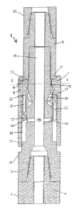
Figure 1 is a sectional side elevation of an attachment according to a first
embodiment
of the present invention on a down-the-hole hammer, showing the positions of
the
sleeve and piston when no restriction is present;
Figure 2 is a sectional side elevation of the attachment of Figure 1, showing
the piston
in the strike position;
WO 2012/020058 CA 02806986 2013-01-29 PCT/EP2011/063778
7
Figure 3 is a sectional side elevation of the attachment of Figure 1, showing
the piston at
top of stroke;
Figure 4 is a cross-sectional view of the attachment of Figure 1, taken along
line X-X;
Figure 5 is an exploded perspective view of the attachment of Figure 1;
Figure 6 is a sectional side elevation of an attachment according to a second
embodiment of the present invention on a down-the-hole hammer, showing the
position
of the sleeve when no restriction is present;
Figure 7 is a sectional side elevation of the attachment of Figure 6, showing
the sleeve
in the open position;
Figure 8 is an exploded perspective view of the attachment of Figure 6; and
Figure 9 is an exploded perspective view of the attachment of Figure 6, from
an
alternative viewpoint.
Detailed Description of the Drawings
Referring to Figures 1 to 5, a first embodiment of an attachment 1 for a
percussion drill
tool 2 comprises a central shaft 3. A lower part of the shaft 3 is internally
screw-
threaded for attachment to a backhead assembly 4 of the hammer 2. The
attachment 1
further comprises a locking sub 9, which is internally screw-threaded at a
lower part
thereof for attachment to the upper end of the shaft 3. An upper part of the
locking sub
9 is externally screw-threaded for attachment to a drill rod 10. The central
shaft 3 and
the locking sub 9 define a central bore 16 for supply of pressurised air to
the hammer 2.
A sleeve 5, hereinafter referred to as a digout sleeve, is co-axially slidably
mounted on
the shaft 3 and is prevented from rotational movement by means of a splined
coupling 6
with the shaft. The sleeve 5 is provided with an external annular shoulder 7
at an upper
end thereof, hereinafter referred to as a restriction shoulder. The
restriction shoulder 7
is provided with tungsten carbide inserts 11. The digout sleeve is slidable
between a
closed position as shown in Figure 1, in which an angled face 8 adjacent the
shoulder 7
is seated against a lower end 12 of the locking sub 9, and an open position
shown in
Figure 2, in which a lower end 13 of the digout sleeve 5 abuts an external
shoulder 14
provided on the central shaft 3. The digout sleeve is further formed with an
internal
annular shoulder or pressure face 17 at an upper part thereof The pressure
face 17 is
WO 2012/020058 CA 02806986 2013-01-29 PCT/EP2011/063778
8
downward facing. A chamber 18 is defined between the sleeve 5 and the shaft 3,
with
the internal face 17 defining the upper end of the chamber 18.
The central shaft 3 is formed with a plurality of ports 19 such that the
chamber 18 is in
fluid communication with the central bore 16. A further plurality of dogleg
ports 20 is
provided between the chamber 18 and the splined portion 6 of the shaft.
A piston 15 is mounted for reciprocal movement within the chamber 18 to strike
the
internal face 17 of digout sleeve 5 to impart a percussive force to the
sleeve. The
piston has an upper annular face 22 and a lower annular face 24. The piston is
provided
with a first plurality of channels 21 extending between the upper face 22 and
a lower
part of the piston inner surface. The piston is also provided with a second
plurality of
channels 23 extending between the lower face 24 and an upper part of the
piston inner
surface.
Under normal operating conditions, the digout sleeve 5 is maintained in the
closed
position shown in Figure 1 by the piston 15. The piston is forced against the
internal
face 17 of the sleeve 5 by the pressurised air supplied to chamber 18 through
ports 19.
This in turn forces the sleeve upwards to seat the angled face 8 against the
lower end 12
of the locking sub. In this position, the hammer operates as normal. No air is
flushed
from the digout sleeve and so the efficiency of the hammer is not affected.
If a restriction is encountered when the hammer is to be withdrawn from the
drilled
hole, the sleeve 5 slides down against the upward force provided by the piston
15 as
shown in Figure 2. This moves the piston 15 into an active position in which
it begins
to cycle. Pressurised air from the central bore 16 is supplied through ports
19
alternately into channels 21 and 23 as shown in Figures 2 and 3. In the first
part of the
cycle, as shown in Figure 2, pressurised air is supplied through ports 19 into
channels
21 and into upper portion 25 of the chamber adjacent internal shoulder 17.
Simultaneously, air exhausts through channels 23 and ports 20 and flushes
through the
splined coupling 6. As a result, the piston moves downwards to the "top of
stroke"
position shown in Figure 3. In the second part of the cycle, shown in Figure
3, air
exhausts from chamber 25 through channels 21 and ports 20, through the splined
WO 2012/020058 CA 02806986 2013-01-29 PCT/EP2011/063778
9
coupling 6. Pressurised air is supplied through ports 19 into channels 23,
causing the
piston to move upwards to the strike position shown in Figure 2. This
reciprocal motion
of the piston in turn causes the restriction shoulder 7 of the digout sleeve 5
to hammer
upwards through the restriction.
The attachment described above has the advantage of only being deployed when a
restriction is encountered. During normal operation of the hammer, the digout
sleeve is
held in the closed position and no air is flushed. When a restriction is
encountered, the
attachment deploys automatically to hammer through the restriction, ensuring
retrieval
of the hammer from the drilled hole.
Referring to Figures 6 to 9, a second embodiment of an attachment 101 for a
percussion
drill tool 102 comprises a central shaft 103. A lower part of the shaft 103 is
internally
screw-threaded for attachment to a backhead assembly 104 of the hammer 102.
The
attachment 101 further comprises a locking sub 109, which is internally screw-
threaded
at a lower part thereof for attachment to the upper end of the shaft 103. An
upper part
of the locking sub 109 is externally screw-threaded for attachment to a drill
rod 110.
The central shaft 103 and the locking sub 109 comprise a central bore 116 for
supply of
pressurised air to the hammer 102.
A digout sleeve 105 is co-axially slidably mounted on the shaft 103 and is
prevented
from rotational movement by means of a splined coupling 106 with the shaft.
The
sleeve 105 is provided with an external annular restriction shoulder 107 at an
upper end
thereof. The restriction shoulder 107 is provided with tungsten carbide
inserts 111. The
digout sleeve is slidable between a closed position as shown in Figure 6, in
which an
angled face 108 adjacent the shoulder 107 is seated against a lower end 112 of
the
locking sub 109, and an open position shown in Figure 7, in which a lower end
113 of
the digout sleeve 105 abuts an external shoulder 114 provided on the central
shaft 103.
The digout sleeve is further formed with an internal annular shoulder 117 such
that a
chamber 118 is provided between the sleeve 105 and the shaft 103. The digout
sleeve
105 is provided with an internal circumferential groove 121 above the annular
shoulder
117. A plurality of channels 123 extend between the groove 121 and the angled
face
108.
WO 2012/020058 CA 02806986 2013-01-29 PCT/EP2011/063778
10
The central shaft 103 is formed with a first plurality of ports 119 such that
the chamber
118 is in fluid communication with the central bore 116. A further plurality
of ports 120
is provided above the chamber 118.
Under normal operating conditions, the digout sleeve 105 is maintained in the
closed
position shown in Figure 6. The digout sleeve is forced upwards to seat the
angled face
108 against the lower end 112 of the locking sub by the pressurised air
supplied to
chamber 118 through ports 119 acting on the internal shoulder 117. Ports 120
are
sealed by the internal wall of the digout sleeve 105. In this position, the
hammer
operates as normal. No air is flushed from the digout sleeve and so the
efficiency of the
hammer is not affected.
If a restriction is encountered when the hammer is to be withdrawn from the
drilled
hole, the sleeve 105 slides down against the upward force provided by the
pressurised
air, as shown in Figure 7. Pressurised air from the central bore 116 is
supplied through
ports 120 into groove 121 and channels 123 and exhausts adjacent the
restriction
shoulder 107 to clear the restriction. Simultaneously, pressurised air is
supplied
through ports 119 into chamber 118 to act on internal shoulder 117. Once the
restriction
has been cleared (or partially cleared), the digout sleeve 105 will move back
to the
closed position due to the pressurised air acting on shoulder 117.
As with the previous embodiment, the attachment described above has the
advantage of
only being deployed when a restriction is encountered. During normal operation
of the
hammer, the digout sleeve is held in the closed position and no air is
flushed. When a
restriction is encountered, the attachment deploys automatically to flush air
through the
restriction, ensuring retrieval of the hammer from the drilled hole.
The words "comprises/comprising" and the words "having/including" when used
herein
with reference to the present invention are used to specify the presence of
stated
features, integers, steps or components but does not preclude the presence or
addition of
one or more other features, integers, steps, components or groups thereof.
WO 2012/020058 CA 02806986 2013-01-29 PCT/EP2011/063778
11
It is appreciated that certain features of the invention, which are, for
clarity, described in
the context of separate embodiments, may also be provided in combination in a
single
embodiment. Conversely, various features of the invention which are, for
brevity,
described in the context of a single embodiment, may also be provided
separately or in
any suitable sub-combination.