Note: Descriptions are shown in the official language in which they were submitted.
CA 02807076 2013-01-23
WO 2012/012828 PCT/AU2011/000942
- 1 -
EXCAVATION TOOTH ASSEMBLY
Technical Field
The present disclosure relates to excavation tooth assemblies including
shrouds and other types of wear assemblies. The present disclosure also
relates to a
digging assembly comprising more than one excavation tooth assembly. The
present
disclosure also relates to parts of the excavation tooth assemblies including
tooth members
and shroud wear members. The disclosure has application in land based digging
equipment
and is herein described in that context. However, it is to be appreciated that
the disclosure
has broader application for example in waterborne excavation equipment such as
dredgers,
and is therefore not limited to that application.
Background
Excavation teeth are provided on the digging edge of various pieces of
digging equipment such as the buckets of front end loaders and the cutting bit
of dredgers.
The excavation teeth may include digging teeth that act as the main ground
engaging parts
of the digging equipment and shrouds disposed between the digging teeth which
provide
wear protection for the digging edge lip. Each excavation tooth is formed of a
number of
parts; for example, the digging teeth may comprise a point and an adapter (or
nose) and in
some arrangements an intermediate member between the point and the adapter. A
shroud
may comprise a shroud wear member and a base member. Each excavation tooth
typically
also comprises a lock or locks to lock the various parts together. The reason
why
excavation teeth are formed of a number of parts is to avoid having to discard
the entire
tooth when the only a part of the tooth is worn or broken.
Various types of locks, points, adapters, shroud wear members, base
members, noses and intermediate members are known. However, it is always
desirable to
design new excavation tooth assemblies and parts thereof.
Summary of the Invention
According to one aspect of the present disclosure, there is provided a tooth
member of an excavation tooth assembly, the tooth member comprising a body
having
opposite first and second ends, and a projecting portion extending in a
longitudinal direction
towards said first end, the projecting portion having a top surface and a
bottom surface; and
opposite sides extending between said top and bottom surfaces, the projecting
portion being
configured with spaced apart side regions extending in the longitudinal
direction and being
defined by portions of the top and bottom surfaces and respective ones of the
sides; and a
mid region disposed between said side regions, wherein the mid region is
recessed relative
to the side regions along at least a portion of at least one of the top and
bottom surfaces.
CA 02807076 2013-01-23
WO 2012/012828 PCT/AU2011/000942
- 2 -
The tooth member may be a nose which has a coupling portion at the nose's
second end which is welded into a recess formed in the digging edge of a
bucket or dredger
cutting bit or other digging equipment. In another embodiment, the tooth
member may be an
adapter, which may have arms extending from the second end of the body, the
arms for
fixing to the digging edge of a bucket or dredger cutting bit or other digging
equipment. The
adapter may alternatively incorporate some other mechanism for fastening the
adapter to
the digging edge of such digging equipment. In a further embodiment, the tooth
member
may be an intermediate member between a point and an adapter (or nose) in an
excavation
tooth assembly. In this embodiment, the body of the tooth member also
incorporates a
socket opening at the second end of the body and configured to receive a
projecting portion
of the adapter (or nose). In another embodiment, the tooth member may be a
shroud wear
member that is disposed between the digging teeth that comprise an adaptor and
a point.
The shroud wear member may be attached directly to the digging edge of the
digging
equipment or is connected to a base member that is mounted to the digging
edge.
The mid region may be recessed in both the top and bottom surfaces of the
body.
The recess defined by the mid region may extend from the first end of the
body towards the second end of the body, preferably parallel to the
longitudinal axis of the
body.
In the embodiment where the mid region is recessed in both the top and
bottom surfaces, the recesses are axially aligned in their longitudinal
direction.
The top surface and the bottom surface may converge towards the first end of
the body.
The first side region may define broad arcuate surface portions in the top
and/or bottom surfaces of the projecting portion.
The second side region may define broad arcuate surface portions in the top
and/or bottom surfaces of the projecting portion.
The broad arcuate surface portions may be convexly curved surfaces and
may curve from one of the sides of the projecting portion to the mid region of
the projecting
portion.
The recess defined by the mid region may be a concavely curved surface,
preferably forming a concave trough between the first and second side regions.
The first end of the body may finish in a front face. The top and bottom
surfaces of the projecting portion may converge towards this front face. The
front face may
also extend between the first and second sides of the projecting portion.
In one embodiment, the front face is shaped with a convex curve between the
first and second sides of the projecting portion.
CA 02807076 2013-01-23
WO 2012/012828 PCT/AU2011/000942
- 3 -
At the first side of the body is a first side surface extending between the
top
surface and the bottom surface.
At the second side of the body is a second side surface extending between
the top surface and the bottom surface.
The first and second side surfaces may converge towards the first end of the
body.
The first and/or second side surfaces may be concave between the top and
bottom surfaces of the body.
The body of the tooth member may also incorporate a cavity for receiving a
lock to lock the tooth member to a further tooth member.
The cavity may be located in the projecting portion of the tooth member is
configured to be received.
The cavity may extend between the first and second sides of the body, in
which embodiment the cavity opens in the first and second side surfaces.
The tooth member may have curved transition segments at the openings of
the cavity, the transition segments curving from the side surfaces of the
projecting portion to
an internal surface defining the cavity.
The projecting portion may taper between the top and bottom surfaces. In
one form, the projecting portion is wider at the top surface than at the
bottom surface, but in
another embodiment may be wider at the bottom surface than at the top surface.
In other embodiments, the side surfaces are planar and may or may not be
orthogonal to the longitudinal axis of the body.
According to another aspect of the present disclosure, there is provided a
tooth member of an excavation tooth assembly, the tooth member comprising a
body having
opposite first and second ends, and a socket extending in a longitudinal
direction towards
said first end from an opening in the second end, the socket defined by a top
inner surface
and a bottom inner surface of the body; and opposite sides extending between
said top and
bottom inner surfaces, the socket being configured with spaced apart side
regions extending
in the longitudinal direction and being defined by portions of the top and
bottom inner
surfaces and respective ones of the sides; and a mid region disposed between
said side
regions, wherein the mid region is reduced in height relative to the side
regions by a
projection along at least a portion of at least one of the top and bottom
inner surfaces.
The socket of the tooth member of this second aspect of the invention is
correspondingly shaped to the projecting portion of the tooth member of the
first aspect of
the present invention so as to receive the projecting portion therein.
The tooth member of this second aspect of the present invention may be a
point in which the body of the tooth member incorporates a digging edge at the
first end. In
another embodiment, the tooth member may be an intermediate member between a
point
CA 02807076 2013-01-23
WO 2012/012828
PCT/AU2011/000942
- 4 -
and a nose of the excavation tooth assembly. The body of the intermediate
tooth member
also incorporates a projecting portion at the first end which is configured to
be received in
the socket of the point.
The projection defining the mid region may extend from the second end of the
body towards the first end of the body, preferably parallel to the
longitudinal axis of the body.
The projection defining the mid region may comprise a ridge on each of the
top and bottom inner surfaces. In this embodiment, the ridges may be axially
aligned in their
longitudinal direction.
The mid region may be reduced in height relative to the side regions by ridges
on each of the top and bottom inner surfaces.
The top inner surface and the bottom inner surface may converge towards the
first end of the body.
The first side region may define broad arcuate surface portions in the top
and/or bottom inner surfaces of the socket.The second side region may define
broad arcuate surface portions in the top
and/or bottom inner surfaces of the socket.
The broad arcuate surface portions may be concavely curved surfaces and
may curve from one of the sides of the socket to the mid region of the socket.
second side regions. The ridge may be a convexly curved
ridge located between the first and
The socket may finish towards the first end of the body in an inner end face.
The top and bottom inner surfaces of the socket may converge towards this
inner end face.
The inner end face may also extend between the first and second sides of the
socket.
In one embodiment, the inner end face is shaped with a concave curve
between the first and second sides of the socket.
At the first side of the socket is a first inner side surface extending
between
the top inner surface and the bottom inner surface.
At the second side of the socket is a second inner side surface extending
between the top inner surface and the bottom inner surface.
The first and second inner side surfaces may converge towards the first end
of the body.
The tooth member may have a recess formed in at least one of the first and
second side surfaces of the body.
Each recess may extend in the longitudinal direction of the body.
The first and/or second inner side surfaces may be convex between the top
and bottom inner surfaces of the socket.
CA 02807076 2013-01-23
WO 2012/012828 PCT/AU2011/000942
- 5 -
The socket may taper between the top and bottom inner surfaces. In one
form, the socket is wider at the bottom inner surface than at the top inner
surface, but in
another embodiment may be wider at the top inner surface than at the bottom
inner surface.
In other embodiments, the inner side surfaces are planar and may or may not
be orthogonal to the longitudinal axis of the body.
According to a further aspect of the present disclosure, there is provided a
tooth member of an excavation tooth assembly, the tooth member comprising a
body having
opposite first and second ends, and a projecting portion extending in a
longitudinal direction
towards said first end, the projecting portion having a top surface and a
bottom surface; and
opposite sides extending between said top and bottom surfaces, wherein the
first end of the
body finishes in a front face, which is shaped with a convex curve between the
first and
second sides of the projecting portion.
According to a further aspect of the present disclosure, there is provided a
tooth member of an excavation tooth assembly, the tooth member comprising a
body having
opposite first and second ends, and a socket extending in a longitudinal
direction towards
said first end from an opening in the second end, the socket defined by a top
inner surface
and a bottom inner surface of the body; and opposite sides extending between
said top and
bottom inner surfaces, wherein the socket finishes towards the first end of
the body in an
inner end face which is shaped with a concave curve between the first and
second sides of
the socket.
According to a further aspect of the present disclosure, there is provided a
tooth member of an excavation tooth assembly, the tooth member comprising a
body having
opposite first and second ends, and a projecting portion extending in a
longitudinal direction
towards said first end, the projecting portion having a top surface and a
bottom surface; and
opposite sides extending between said top and bottom surfaces, wherein the
projecting
portion tapers between the top and bottom surfaces.
According to a further aspect of the present disclosure, there is provided a
tooth member of an excavation tooth assembly, the tooth member comprising a
body having
opposite first and second ends, and a socket extending in a longitudinal
direction towards
said first end from an opening in the second end, the socket defined by a top
inner surface
and a bottom inner surface of the body; and opposite sides extending between
said top and
bottom inner surfaces, wherein the socket tapers between the top and bottom
inner
surfaces.
According to a further aspect of the present disclosure, there is provided a
tooth member of an excavation tooth assembly, the tooth member comprising a
body having
opposite first and second ends, and a projecting portion extending in a
longitudinal direction
towards said first end, the projecting portion having a top surface and a
bottom surface; and
opposite sides extending between said top and bottom surfaces, the sides
defined by first
CA 02807076 2013-01-23
WO 2012/012828 PCT/AU2011/000942
- 6 -
and second side surfaces extending between the top surface and the bottom
surface, the
side surfaces being planar and substantially orthogonal to the longitudinal
axis of the body.
According to an further aspect of the present disclosure, there is provided a
tooth member of an excavation tooth assembly, the tooth member comprising a
body having
opposite first and second ends, and a socket extending in a longitudinal
direction towards
said first end from an opening in the second end, the socket defined by a top
inner surface
and a bottom inner surface of the body; and opposite sides extending between
said top and
bottom inner surfaces, the sides defined by first and second inner side
surfaces extending
between the top inner surface and the bottom inner surface, the inner side
surfaces being
planar and substantially parallel and substantially orthogonal to the
longitudinal axis of the
body.
According to an further aspect of the present disclosure, there is provided a
tooth member of an excavation tooth assembly, the tooth member comprising a
body having
opposite first and second ends, and a projecting portion extending in a
longitudinal direction
towards said first end, the projecting portion having a top surface and a
bottom surface, and
opposite sides extending between said top and bottom surfaces, wherein the
tooth member
has a recess formed in at least one of the first and second side surfaces of
the body.
The tooth member may have a recess in each of the first and second side
surfaces of the body.
Each recess may extend in the longitudinal direction of the body.
The first and/or second side surfaces may be concave between the top and
bottom surfaces of the body.
Each recess may be shaped to enable the tooth member to fit in abutment
against an adjacent tooth member when installed on digging equipment.
According to an further aspect of the present disclosure, there is provided a
digging assembly for attachment to digging equipment, the digging assembly
comprising at
least first and second excavation tooth assemblies, each excavation tooth
assembly
comprising a tooth member configured to be attached to the digging equipment
adjacent to
the tooth member of another excavation tooth assembly, the tooth member of
each
excavation tooth assembly having at least one side surface that is shaped to
enable the
tooth member to be attached to the digging equipment with at least one of its
side surfaces
in fitment with the side surface of an adjacent tooth member.
The side surface of one of the adjacent tooth members may be recessed, in
which embodiment the side surface of the other adjacent tooth member that is
configured to
be in fitment with the side surface of the first mentioned tooth member is
projected.
CA 02807076 2013-01-23
WO 2012/012828 PCT/AU2011/000942
- 7 -
Brief Description of the Drawings
Embodiments of the present disclosure will now be described by way of
example only, in which:
Figure 1 is a top view of an intermediate member coupled to a nose in an
excavation tooth assembly according to an embodiment of the present
disclosure;
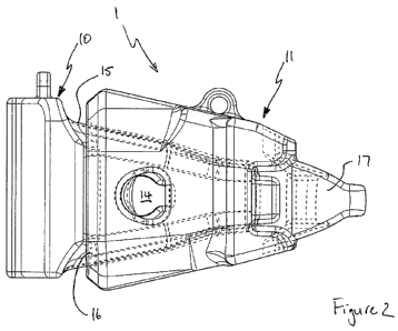
Figure 2 is a side view of the intermediate member and nose of Figure 1;
Figures 3 and 4 are perspective views of the intermediate member and nose
of Figure 1;
Figure 5 is an end view of the intermediate member of Figure 1;
Figure 6 is a perspective end view of the intermediate member of Figure 1;
Figures 7 and 8 are upper and lower perspective views of the nose of
Figure 1;
Figures 9(A) and 9(B) are upper and lower perspective views of the projecting
portion of a nose according to another embodiment of the present disclosure in
isolation;
Figure 10 is a side view of the projecting portion of Figure 9;
Figure 11 is a top view of the projecting portion of Figure 9;
Figure 12 is a front end view of the projecting portion of Figure 9;
Figure 13A.-13F. is a perspective, top, bottom, rear, side and front views of
a
shroud wear member of an excavation tooth assembly according to an embodiment
of the
present disclosure;
Figure 14 is a perspective view of the digging edge of excavator bucket with a
plurality of the shroud wear members of Figure 13 attached to the digging
edge, each
shroud wear member having adjacent on either side an excavation tooth assembly
according to the embodiment in Figure 1; and
Figure 15 is front view of the digging edge of Figure 14.
Detailed Description of the Embodiments
Referring to the Figures 1-8, there is shown a nose or adaptor and an
intermediate member of an excavation tooth assembly, being a digging tooth
assembly 1,
according to embodiments of the present disclosure. The nose 10 may be mounted
to the
digging edge of digging equipment (such as the buckets of front end loaders or
the cutting
bit of dredgers) by welding a rear portion of the nose into a recess formed in
the digging
edge. In another form, the nose may be integrally cast with a lip member that
forms the
digging edge of the digging equipment. The intermediate member 11 couples to
the nose
10. Not shown in these Figures, but also forming a part of the excavation
tooth assembly is
a point which couples to the intermediate member 11 and comprises a digging
edge which
engages the ground in use. Also not shown but which forms a part of the
excavation tooth
CA 02807076 2013-01-23
WO 2012/012828 PCT/AU2011/000942
- 8 -
assembly are locks for locking the intermediate member to the nose and the
point to the
intermediate member.
To couple the intermediate member to the nose, the nose 10 comprises a
body having opposite first and second ends and a projecting portion 15
extending in the
longitudinal direction towards the first end and the intermediate member 11
comprises a
body having opposite first and second ends and a socket 16 which opens at the
second end
and extends in the longitudinal direction towards the first end, the
projecting portion and
socket configured to be coupled together with the projecting portion received
in the socket.
The socket 16 of the intermediate member 11 is therefore provided with a shape
which
generally corresponds to the shape of the projecting portion 15 of the nose
10. A cavity 14
is provided through the projecting portion 15 of the nose which aligns with
openings 38, 39
through walls of the socket 16. A lock (not shown) is positioned relative to
the cavity 14 and
the openings 38, 39 to lock the intermediate member to the nose so as to
retain the
projecting portion 15 in the socket 16.
The body of the intermediate member also incorporates a projecting portion
17 which is configured to be received in a socket of the point of the
excavation tooth
assembly. A cavity 18 is provided in the projecting portion 17 for receipt
therein of a lock
(not shown) for locking the point to the intermediate member. The projecting
portion 17 of
the intermediate member could be designed to have features similar to the
projecting portion
15 of the nose, which would mean that the socket of the point would have
similar features to
the socket 16 of the intermediate member 11. However, in the embodiments shown
in the
Figures, the projecting portion 17 of the intermediate member is of a
different design to the
projecting portion 15 of the nose.
Referring now specifically to Figures 7 and 8, the projecting portion 15 of
the
nose 10 is shown in isolation. The projecting portion 15 has a top surface 20,
a bottom
surface 21 and opposite side surfaces 22, 23 extending between the top and
bottom
surfaces. The projecting portion 15 also has spaced apart side regions 24, 25
and a mid
region 26 disposed between and spacing apart the side regions. The mid region
26 is
recessed relative to the side regions 24, 25 along the top and bottom surfaces
20, 21. This
structure, which is based on an I-beam profile, provides both increased
stability for the tooth
members joined via this projecting portion structure as well as increased
strength for the
projecting portion in torsion. It is noted that although in the illustrated
embodiment the mid
region 26 is recessed along the length of the projecting portion 15, in other
embodiments,
the mid region may be recessed only part of the length of the projecting
portion.
The side regions 24, 25 are defined by broad arcuate surface portions of the
top and bottom surfaces 20, 21 which are convexly curved and extend the length
of the
projecting portion 15 from the first end of the nose body towards the second
end of the nose
body. Each broad arcuate surface portion curves between the top or bottom of
one of the
CA 02807076 2013-01-23
WO 2012/012828 PCT/AU2011/000942
- 9 -
side surfaces to the mid region of the projecting portion. These broad arcuate
surface
portions reduce the contact pressure between the projecting portion 15 and the
socket in
which the projecting portion is received in use. The mid region 26 is defined
by a concavely
curved trough in each of the top and bottom surfaces 20, 21 which extend the
length of the
projecting portion 15. Each trough curves between the first and second side
regions. The
mid region 26 is located centrally in the projecting portion 15 with the
troughs axially aligned
such that a longitudinal axis of the mid region defines an axis of symmetry of
the projecting
portion 15.
The top and bottom surfaces 20, 21 of the projecting portion 15 converge
towards the first end of the nose body, with the projecting portion ending in
a front face 27
extending between the top and bottom surfaces as well as side surfaces 22, 23.
In the
embodiment shown in the Figures, this front face 27 is convex between the side
surfaces 22,
23 of the projecting portion 15 so as to reduce contact pressure between the
projecting
portion 15 and the socket in which he projecting portion is received. However,
in other
embodiments, the front face may be substantially planar between the side
surfaces.
In the embodiment shown in Figures 7 and 8, the top and bottom surfaces 20,
21 are of approximately equal width along the length of the projecting portion
15. However,
Figures 9-12 show another embodiment, in which the projecting portion tapers
between the
top and bottom surfaces with the bottom surface being wider than the top
surface. Although,
the projecting portion may be formed with the top surface wider than the
bottom surface.
The opposite side surfaces 22, 23 also converge towards the first end of the
nose body. The side surfaces 22, 23 are also each concavely shaped between the
top and
bottom surfaces 20, 21. This shaping reduces the contact pressure between the
projecting
portion 15 and the socket in which it is received when the excavation tooth is
twisted. The
concave side surfaces 22, 23 also provides a smoother geometric transition
into the cavity
14 (ie. there are no sharp corners), which reduces the stresses around the
cavity 14 both
during manufacture and use of the nose. These stresses are also reduced by
curved
transition segments 28 at the openings of the cavity 14. The transition
segments 28 curve
from the side surfaces 22, 23 of the projecting portion 15 to an internal
surface 29 defining
the cavity.
It is noted that in other embodiments, the side surfaces are planar. In these
embodiments, the side surfaces may or may not be orthogonal to the
longitudinal axis of the
body.
Referring now more specifically to Figures 5 and 6, the intermediate member
11 and in particular the socket 16 of the intermediate member is shown. The
inner surface
of the socket 16 is shaped to match and fit with the outer surface of the
projecting portion 15
of the nose 10 as described above. The body of the intermediate member 11
comprises top,
bottom and opposite side walls 30, 31, 32, 33 having top, bottom and opposite
inner side
CA 02807076 2013-01-23
WO 2012/012828 PCT/AU2011/000942
- 10 -
surfaces 34, 35, 36, 37 respectively which define the socket 16. Openings 38,
39 are
provided through the side walls 32, 33 of the intermediate member body to the
socket 16, so
as to provide access to (and for engagement by if so designed) the lock which
locks the
intermediate member 11 to the nose 10.
When the excavation tooth assembly is assembled, clearance is provided
between respective top and bottom surfaces of the projecting portion 15 and
the socket 16
(although the apexes/antapexes of the side and mid regions may be in contact),
with
respective side surfaces substantially contacting one another. However, in
other variations,
the respective side surfaces may have clearance with the respective top and
bottom
surfaces are in substantial contact or all of the respective top, bottom and
side surfaces may
be in substantial contact.
The socket 16 also has spaced apart side regions 40, 41 and a mid region 42
disposed between and spacing apart the side regions. The mid region 42 is
reduced in
height relative to the side regions 40, 41 by projections in the form of
ridges 50, 51 along the
top and bottom inner surfaces 34, 35.
The side regions 40, 41 are defined by broad arcuate surface portions of the
top and bottom inner surfaces 34, 35 which are concavely curved and extend the
length of
the socket 16 from the second end of the intermediate member body towards the
first end of
the intermediate member body. Each broad arcuate surface portion curves
between the top
or bottom of one of the inner side surfaces to the mid region of the socket.
The mid region 42 is defined by the convexly curved ridges 50, 51 on each of
the top and bottom inner surfaces 34, 35 which extend the length of the socket
16. Each
ridge 50, 51 curves between the first and second side regions. The mid region
42 is located
centrally in the socket 16 with the ridges axially aligned such that a
longitudinal axis of the
mid region defines an axis of symmetry of the socket 16.
The top and bottom surfaces 34, 35 of the socket 16 converge towards the
first end of the intermediate member body, with the socket ending in an inner
end face 43
extending between the top and bottom inner surfaces as well as inner side
surfaces 36, 37.
In the embodiment shown in the Figures, this inner end face 42 is concave
between the
inner side surfaces 36, 37 of the socket 16 so as to reduce contact pressure
between the
socket 16 and the projecting portion received therein. However, in other
embodiments, the
inner end face may be substantially planar between the inner side surfaces.
In the embodiment shown in Figures 1-8, the socket has top and bottom inner
surfaces 34, 35 which are of approximately equal width along the length of the
socket.
However, in other embodiments, the socket may taper between the top and bottom
inner
surfaces 34, 35, with the top or bottom inner surface being wider than the
other.
The opposite inner side surfaces 36, 37 also converge towards the first end of
the intermediate member body. The inner side surfaces 36, 37 are also each
convexly
CA 02807076 2013-01-23
WO 2012/012828 PCT/AU2011/000942
- 11 -
shaped between the top and bottom inner surfaces 34, 35. However, in other
embodiments,
the inner side surfaces are planar. In these embodiments, the inner side
surfaces may or
may not be orthogonal to the longitudinal axis of the body.
In another variation to the embodiments shown in the Figures, the projecting
portion of the nose may be formed with planar portions at the apexes of the
side regions
and/or the antapexes of the recessed mid region. Similarly, the socket of the
intermediate
member may be formed with planar portions at the antapexes of the recessed
side regions
and/or the apexes of the projection mid regions. The planar portions formed at
the side
regions of the projecting portion may be parallel to or slanted transverse to
the longitudinal
direction of the nose with respect to each other. The planar portions formed
at the side
regions of the socket may be similarly shaped. During use of the excavation
tooth
assembly, the top and bottom surfaces of the nose and the socket of the
intermediate
member undergo the greatest amount of wear. To extend the operational life of
the nose
and the intermediate member, repairs can be made in which weld is added to the
worn
surfaces to return them generally to their original shape. The planar portions
at the
apexes/antapexes provide a shape which is easier to gauge when conducting such
repairs.
Referring now to Figures 13-15, an excavation tooth assembly, in the form of
a shroud assembly 60, is shown. The shroud assembly 60 is particularly
configured to
protect the lip edge 61 of the digging equipment to which it is attached. In
the embodiment
shown in Figures 13-15 each shroud assembly 60 is disposed between and thus
protects
the lip edge 61 between digging teeth assemblies 1 according to the embodiment
shown
and described in respect of Figures 1-12. However, in other embodiments, there
are no
digging teeth assemblies provided on the digging equipment and the shroud
assemblies 60
are disposed along the length of the lip of the digging equipment adjacent one
another.
Each shroud assembly 60 comprises a shroud wear member 62 which is
shown in detail in Figure 13. The shroud wear member 62 may be attached
directly to the
digging equipment about the lip edge 61. Alternatively, each shroud assembly
may comprise
a base member that is attached to the digging equipment and to which its
respective shroud
wear member 62 is mounted. Each shroud assembly also comprises a lock (not
shown)
which the locks the shroud wear member 62 in its attachment to the digging
equipment.
The shroud wear member 62 has a first end and a second and comprises a
projecting portion 65 extending in a longitudinal direction towards the first
end and first and
second legs 66, 67 extending away from the projecting portion and towards the
second end.
The first and second legs 66, 67 are spaced apart and configured to fit over
and engage
opposed surfaces of the digging equipment. A locking cavity 68 is provided in
the first leg 66
for receiving the lock to lock the shroud wear member 62 to the digging
equipment. The
projecting portion 65 has a top surface 70, a bottom surface 71 and opposite
side surfaces
72, 73 extending between the top and bottom surfaces. The top and bottom
surfaces 70, 71
CA 02807076 2013-01-23
WO 2012/012828 PCT/AU2011/000942
- 12 -
converge towards the first end of the shroud wear member 62. The top surface
70 is also
provided with self-sharpening pockets 74. These pockets 74 help maintain a
pointed profile
for the shroud wear member 62 is it wears so that it can still effectively
penetrate into soil.
The pockets 74 also have the additional benefit of lightening the shroud wear
member 62.
The top surface of the shroud wear member 62 may also be provided with a wear
indicator
in the form of a shallow recess which provides a quick visual indication of
how much the
shroud wear member 62 has worn during use and whether it might require
replacement.
Each of the side surfaces 72, 73 of the projecting portion 65 are recessed.
Each recess 75, 76 in the side surfaces extend in the longitudinal direction
of the projecting
portion 65 and have curved portions so that the side surfaces 72, 73 are
somewhat concave
between the top and bottom surfaces 70, 71 of the projecting portion. A
particular advantage
of the recesses 75, 76 in the side surfaces 72, 73 of the shroud wear member
62 is that
enables the wear member 62 to be in close fitment with the side of adjacent
tooth members
attached to the digging equipment that projects of bulges. This is shown, for
example, in
Figures 14 and 15. As a result, the entire length of the lip edge of the
digging edge is
protected from wear.
It is to be understood that, unless indicated otherwise by express language or
necessary implication, the tooth members including noses (adaptors),
intermediate
members, points and shroud wear members according to any embodiment of one
aspect of
the present disclosure may further encompasses any one or combination of
features
described above in relation to embodiments of other aspects of the present
invention.
It is also to be understood that whilst certain passages of the above
description have been made in respect of a three part digging tooth assembly
comprising a
nose, an intermediate member and a point, these embodiments of the present
disclosure
described above may be incorporated into a two part excavation tooth assembly
comprising
an adaptor and a point with no intermediate member disposed between the
adaptor and the
point.
It is to be further understood that features described above in respect of a
digging tooth assembly may be incorporated into a shroud assembly and vice
versa. That is,
features described above in respect of a shroud assembly may be incorporated
into a
digging tooth assembly.
In the claims which follow and in the preceding description of the invention,
except where the context requires otherwise due to express language or
necessary
implication, the word "comprise" or variations such as "comprises" or
"comprising" is used in
an inclusive sense, i.e. to specify the presence of the stated features but
not to preclude the
presence or addition of further features in various embodiments of the
invention.