Note: Descriptions are shown in the official language in which they were submitted.
CA 02807205 2013-02-21
FIELD OF THE INVENTION
The Invention relates to a plant care device for indicating the water status
of a potted
plant.
BACKGROUND OF THE INVENTION
The care of potted plants requires regular watering in appropriate amounts.
Plants that
are left to dry will die. Plants that receive excessive water will also die.
Where a potted
plant is placed at ground level or waist level, then it is possible for a
knowledgeable
person to regulate the watering of individual pots. However, in many cases
persons will
wish to hang the pots at or above head level typically on the porch of a house
or the
balcony of an apartment or such locations. When this happens, the care person,
no
matter how knowledgeable will have great difficulty in determining the water
status of a
pot. Feeling the earth in the pot with a hand is not always possible, and is
uncertain as
to its reliability. Watering such pots at regular schedules is also not
acceptable. Some
plants require more water and others less.
Accordingly it is desirable to provide a plant care device by means of which
an owner or
plant care person can determine the water status of a particular pot, and
replenish
water or not, as the case may be. In the past, devices have been proposed
which
attempt to measure the water content of the soil. However these devices are
relatively
expensive, and may not always be reliable. In addition, if such a device is
embedded in
the soil in a pot, which is hanging at a considerable height, it is not
possible to see the
reading of the device.
Accordingly, there is a need for a much simpler system for determining the
water
1
CA 02807205 2013-02-21
status of a potted plant, visually, from a distance.
In addition it is desirable that such a device shall be relatively
inexpensive, and can be
reused over and over again, and does not require any sophisticated technology.
Preferably one device will be used with each pot, and left in position
throughout the life
of the plant.
BRIEF SUMMARY OF THE INVENTION
With a view to providing a plant care device indicating the water status of a
potted plant,
the invention provides a hanging pot water indicator having a hollow tubular
spring
housing, typically made of thermo plastic, a dust protector on the upper end
of the
tubular housing, the dust protector having a fastening collar fitting around
the upper
end of the tubular housing, a hollow tubular sliding sleeve, having an
interior diameter
greater than the exterior diameter of the tubular housing, and being
telescopically
slidable in respect thereof, a lower flared portion on the lower end of the
sleeve, an
opening in the dust protector, a coiled extension spring within the tubular
housing and
the sleeve, an upper wire extension portion extending from the upper end of
the spring
passing through the opening in the dust protector, and defining an upper hook,
a lower
wire extension extending from the lower end of the spring, and formed to
define a hook.
Preferably the invention provides retention means located between the collar
on the
dust protector and the upper end of the tubular spring housing retaining the
spring
housing upper end in the collar, and engagement means at the lower end of the
sleeve,
engaging the lower end of the spring.
Preferably, the dust protector will be formed with a mushroom shape to shed
dust.
Preferably, the lower end of the spring will be formed with a outwardly flared
spiral
2
CA 02807205 2013-02-21
portion.
Preferably there will be some visible indicia formed on the tubular spring
housing.
In another embodiment, the indicator may be adapted to operate a remote
indication of
the water status of each plant pot in the system.
The various features of novelty which characterize the invention are pointed
out
with more particularity in the claims annexed to and forming a part of this
disclosure.
For a better understanding of the invention, its operating advantages and
specific
objects attained by its use, reference should be made to the accompanying
drawings
and descriptive matter in which there are illustrated and described preferred
embodiments of the invention.
IN THE DRAWINGS
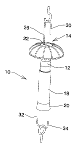
Figure 1 is a general perspective illustration showing a hanging pot water
indicator
illustrating the invention, hanging from a fixed location and supporting a
potted plant;
Figure 2 is a greatly enlarged perspective illustration partly exploded and
cut away, of
the hanging pot water indicator of Figure 1;
Figure 3 is an exploded view of the hanging pot water indicator of figures 1
and 2,
partially cut away; and,
Figure 4 is a schematic side view of an alternate embodiment; and,
Figure 5 is a sectional view of a portion of Figure 4.
3
CA 02807205 2013-02-21
DESCRIPTION OF A SPECIFIC EMBODIMENT
The invention is illustrated in the form of a hanging pot water indicator
(10). Such a
hanging pot water indicator (10) has utility in suspending a flower pot above
the ground,
usually at an elevation where the interior of the flower pot is not visible or
accessible to
a plant care person. Typically there will be one indicator per pot and it will
be left in
place for the life of the plant.
The hanging pot water indicator (10) has a hollow tubular spring housing (12),
typically
made of thermo plastic, and a dust protector (14) on the upper end of the
tubular
housing. The dust protector has a fastening collar (16) fitting around the
upper end of
the tubular housing.
The hanger further comprises a hollow tubular sliding sleeve (18) , having an
interior
diameter greater than the exterior diameter of the tubular housing (12), and
being
telescopically slidable in respect thereof. Sleeve (18) has a lower trumpet
portion (20)
on the lower end of the sleeve.
There is an opening (22) in the dust protector (14).
A coiled extension spring (24) is located within the tubular housing (12) and
the sleeve
(18) . The spring (24) has an upper wire extension portion (26) extending from
the
upper end of the spring (24) passing through the opening (22) in the dust
protector (14)
and defining an upper hook (30). A lower wire extension (32) extends from the
lower
end of the spring (24) , and is formed to define a hook (34).
Retention means (36) such as adhesive, are located between the collar (16) on
the dust
protector (14) and the upper end of the tubular spring housing (12) retaining
the spring
housing upper end in the collar (16).
4
CA 02807205 2013-02-21
Engagement means (38) are located at the lower end of the trumpet portion (20)
of the
sleeve (18), such as a tab, engage the lower end of the spring (24).
The dust protector (14) is formed with an umbrella or mushroom shaped shell
(40)
which sheds dust and acts as a dust protector to prevent entry of foreign
matter
between the housing (12 ) and the sleeve (18). The lower end of the spring is
formed
with an outwardly flared spiral portion (42).
Visible indicia (44) are formed on the tubular spring housing (12)
In use, the hanging pot water indicator is first of all attached to a hook at
an elevation.
The plant pot is then attached to the lower hook (34) of the hanging pot water
indicator.
The tab (38) engages the lower end of the spring (24). As the spring (24) is
extended, it
will draw the sleeve (18) down.
Assuming that the watering status of the plant at that time is adequate, then
it will cause
extension of the spring (24) and the sleeve (18) relative to the housing (12).
As the
water content of the pot dries out, the pot will gradually be drawn upwardly
by the
spring. The spiral flared portion (42) of the spring (24) engages the trumpet
portion (20)
of the sleeve (18) and forces it upwardly.
Visual observation of the position of the sleeve (18) relative to the housing
(12) will give
adequate indication of the water status of that plant in that pot, and then
water can be
added , or the pot can be left unattended according to the observations made.
While the above noted and described hanging pot water indicator will perform
satisfactorily domestic or even office environments where a few hanging plants
are
provided for decoration, it will be appreciated that the invention is of water
application in
the field of commercial horticultural establishments such as commercial
greenhouses
5
CA 02807205 2013-02-21
and flower growing farms.
In these cases, large numbers of hanging flower pots will be either growing,
or available
in inventory, for example in a retail establishment. In these cases, it will
be desirable to
provide for automatic watering of the plants as and when required.
This can be accommodated by means of the further embodiment as shown in
Figures 4
and 5. In this case, a flower pot ( P), is illustrated hanging from a hanging
pot water
indicator (50) of the type generally similar to that described in Figures 1 to
3. In other
words it will have an upper housing (52) and sleeve (54) and a spring (56) .
These will
function in the same way as described above. That is to say that when the
water in the
particular pot (P) is adequate, the hanging pot water indicator (50) will be
somewhat
extended. When the water in the pot (P) becomes insufficient then the hanging
pot
water indicator will be retracted upwardly.
In this embodiment however, water will be supplied automatically, when the
hanging pot
water indicator contracts. In this case it is assumed that numerous such pots
(P) will be
suspended from a rail (60) typically in a greenhouse or commercial
establishments or
for example, in a retail establishment. A transverse water supply pipe (62) is
connected
by means of a supply hose (64) to a valve (66). From the valve (66) water will
be
allowed to trickle down pipe (68) into the pot (P).
In this case, the hanging pot water indicator (50) has an operating rod (70)
attached to
the sleeve (54) (Figure 4). The valve (66) has a lever arm (72) which is
connected to
the operating rod (70). A wall (67) divides valves (66) into the upper and
lower
portions. The water supply pipe (64) connects with the upper portion. A valve
seat
(74), in wall (67) has a closure ball (76), having an internal spring (78)
mounted on a
6
CA 02807205 2013-02-21
valve rod (80). The rod (80) connects with the arm (72)
In this embodiment, the water supply (64) supplies water to the upper portion
of the
valve (66). The ball (76) normally closes seat (74) in the wall (67), thus
preventing
passage of the water downwardly into the lower portion. However when the lever
arm
(72) pushes the rod (80) upwardly against the spring (78), the ball (76) will
lift off its
seat, and water will thus flow downwardly from the upper portion to the lower
portion of
valve (66) and thereby flow outwardly to the outlet pipe (68) down into the
pot. When
sufficient water has flowed into the pot to cause hanging pot water indicator
to become
extended once again, the operating rod (70) will be retracted and the ball
(76) will then
once again seat in its opening in the wall, thereby preventing further flow of
water.
It will be seen that all of this takes place in a simple and economical
structure. In
particular it is noteworthy that once set up in this way with the hanging pot
water
indicator adjusted to allow the correct amount of water, water will be
supplied
automatically to the various pots as needed, individually. All of this will
happen with
each hanging pot being controlled and supplied with water at its own rate, and
without
reference to the other hanging water pots where plants of other species may
require
more or less water or more or less frequent supplies of water.
The foregoing is a description of a preferred embodiment of the invention
which
is given here by way of example only. The invention is not to be taken as
limited to any
of the specific features as described, but comprehends all such variations
thereof as
come within the scope of the appended claims.
7