Note: Descriptions are shown in the official language in which they were submitted.
WO 2012/021426 CA 02807648 2013-02-06 PCT/US2011/046886
Internal Combustion Engine Enhancement Device and Method
BACKGROUND
Field of the Invention
The present invention relates generally to the field of internal
combustion engines and more particularly to a device that tremendously
enhances the performance of any internal combustion engine.
Description of the Problem
It is known in the art to inject hydrogen gas into the air intake of an
internal combustion engine to enhance performance. Several devices are on
the market that create hydrogen electrolytically from water or other liquids.
Also zinc/acid combinations have been used. These methods suffer from
having to supply electricity to the device, inability to control the amount of
gas
produced, corrosive acids, and danger of electrical shock. It would be
tremendously advantageous to have a device that could produce hydrogen
gas on demand from the vehicle's throttle which can then be injected into the
air intake of the engine.
SUMMARY OF THE INVENTION
The present invention relates to a device that can provide hydrogen
gas into an engine's air intake that is demand controlled by the vehicle's
throttle linkage. When the throttle is pressed, hydrogen generation can start
or increase, and when the throttle is released, hydrogen generation can stop
of decrease. The device of the present invention uses the vehicle's own
vacuum to control the production of hydrogen by forcing a liquid to rise in a
chamber and into contact with a metal in response to increasing vacuum, thus
1
SUBSTITUTE SHEET (RULE 26)
WO 2012/021426 CA 02807648 2013-02-06PCT/US2011/046886
producing an increasing amount of hydrogen gas with increasing throttle
depression.
DESCRIPTION OF THE FIGURES
Attention is now directed to several figures that illustrate aspects and
features of the present invention:
Fig. 1 shows a block diagram of an embodiment of the present
invention used in conjunction with an internal combustion engine.
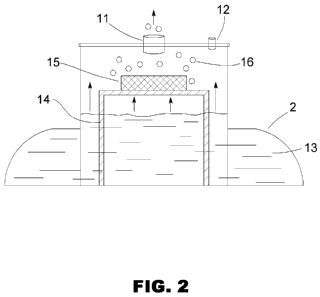
Fig. 2 shows a schematic of the internal construction of an
embodiment of the present invention.
Fig. 3 shows the embodiment of Fig. 2 with an atmospheric balance
tube.
Fig. 4 shows a graph of throttle engagement vs. hydrogen production.
Several drawings and illustrations have been provided to aid in
understanding the features of the present invention. The scope of the present
invention is not limited to what is shown in the figures.
DESCRIPTION OF THE INVENTION
The present invention is directed toward a vacuum controlled device
that can produce hydrogen gas on demand, and under control of a vehicle's
throttle as needed, for injecting into the air intake of an internal
combustion
engine. The present invention can be used with virtually any internal
combustion engine (including diesel engines) and finds applications in cars,
trucks, boats, ships, locomotives, agricultural machines, military vehicles
and
other devices such as mobile power stations, generators and any other
internal combustion engines using gasoline, diesel, natural gas, propane or
any other fuel.
2
WO 2012/021426 CA 02807648 2013-02-06PCT/US2011/046886
Turning to Fig. 1, a block diagram of an embodiment of the present
invention is seen. The internal combustion engine 1 has an air intake 8 where
flow into the air intake is controlled by a valve 6 that is coupled to the
vehicle's
throttle linkage 9, 10. A parallel path of regular air (not shown) can
optionally
be supplied into the air intake at this point if desired. A reaction chamber 2
that can produce hydrogen in quantity and demand to vacuum can be located
near the engine 1. The air intake 8 can be connected through a hose 7 to the
valve 6. The reaction chamber 2 can be connected from its gas outlet 11,
through a hose 3 to a filter 4. The filter 4 can be connected through a hose 5
to the valve 6. An open inlet port 12 on the reaction chamber allows air to
enter and be pulled through the chamber in response to the vacuum.
The filter 4 is optional, but generally recommended to clean the
hydrogen produced by a chemical reaction in the reaction chamber 2. With
no filter, liquid and other byproducts of the reaction might be drawn into the
engine 1. The filter 4 and chemical elements of the reaction chamber 2 are
parts that can be replaced after a certain amount of usage.
Fig. 2 shows a schematic drawing of an embodiment of the reaction
chamber 2. The chamber 2 contains a quantity of liquid 13 that, under a no-
vacuum condition, rests at a particular surface level measured vertically. A
support 14 holds a piece or block of metal 15 on a platform just above the no-
vacuum resting surface level of the liquid 13, with bottom and side surfaces
exposed. When vacuum is drawn in the main exit portal 11 caused by
depressing the vehicle's throttle, the liquid is pulled upward in the reaction
chamber and into contact with the metal 15. The more vacuum pulled, the
more surface contact with the metal. Since the liquid 13 in contact with the
3
WO 2012/021426 CA 02807648 2013-02-06PCT/US2011/046886
metal 15 produces hydrogen gas 16, the amount of vacuum directly controls
the rate of hydrogen production. A portal 12 open to the atmosphere allows
some air to be drawn into the chamber 2 so that the mixture leaving the
chamber 2 via the exit portal 11 contains air mixed with hydrogen. The open
portal 12 is normally smaller in diameter than the exit portal 11. The result
is
a system where engine vacuum under control of the throttle controls the rate
of hydrogen injection into the engine.
Any combination of liquid/metal that produces hydrogen gas can be
used in the chamber 2; however, the preferred liquid is a solution of Sodium
Hydroxide, and the preferred metal is Aluminum. Sodium hydroxide (lye) can
be considered a reactant or catalyst to make the liquid water react with the
metal. Other catalysts are not necessary with this particular combination.
Any liquid/metal combination that produces hydrogen gas, when the metal is
in contact with the liquid, with or without an additional catalyst, is within
the
scope of the present invention. Any catalyst of any type that enhances the
reaction is also within the scope of the present invention; however, as stated
the lye/water combination generally does not need any other catalyst to react.
The minimum requirement for a system is around one milliliter of liquid
(water), around one milligram of metal (aluminum) and around one milligram
of reactant (NaOH). Any other quantities or combinations may be used. In a
typically automobile or vehicle use, the reaction chamber can be around 5-6
inches in diameter, contain from 1 to 4 liters of solution and contain a bar
or
block of metal of several grams up to several hundred grams. A preferred
concentration of NaOH in water is between 5% to 15%. It should be noted
that the reaction described does not need extra heat and does not produce
4
WO 2012/021426 CA 02807648 2013-02-06 PCT/US2011/046886
excessive heat itself. Therefore, there is no need to externally cool the
reaction. No electric current is required, and the solution is not excessively
corrosive. Even though the solution as described generally has a depressed
freezing point over pure water, to prevent freezing on particularly cold days
or
in particularly cold climates, a small amount of alcohol or glycol can be
added
to the mixture without any adverse effect on the reaction.
The rate that the metal is dissolved depends on usage including city or
rural driving, speed driven, etc. A typical auto arrangement can generally
last
around 5000 miles or more. At that point, the liquid and metal can be
refreshed, and the filter replaced. This can be done in conjunction with an
oil
change or other routine maintenance. Any other replacement interval is within
the scope of the present invention.
As previously stated, when the driver applies throttle, the vehicle's
vacuum increases causing the surface of the liquid 13 in the chamber 2 to rise
and contact the bottom and/or side surface of the metal 15, and upon further
rising, contact the sides and possibly even the top surface of the metal 15.
The height of the metal should be sufficient to create an increasing,
approximately linear, increase of hydrogen production as the level rises.
Saturation will occur when the metal is completely submerged. This point
should be chosen near full throttle depression. In a typical vehicle
application,
the height can be from several centimeters to even a lot more. The rate of
liquid rise depends on the diameter of the chamber 2 as well as the amount of
vacuum supplied above the liquid. Automobile engines typically produce
between 90-100 kPa of manifold pressure (vacuum). The chamber diameter
and metal height can be chosen to produce the desired gas production
5
WO 2012/021426 CA 02807648 2013-02-06PCT/US2011/046886
gradient for a given engine or engine/vehicle class. Generally, for the liquid
to
rise in response to decreasing air pressure on its top surface (caused by
increase vacuum above it), the liquid must display a second surface to the
atmosphere. This can be achieved using a U-shaped or an open balance
tube 16 shown in Fig. 3, or any other arrangement that presents a second
liquid surface to the atmosphere. This allows the liquid to flow up and down
in
direct response to increasing or decreasing vacuum. Any method or
arrangement that allows the liquid surface level to rise and fall in direct
response to vacuum is within the scope of the present invention.
The chamber can be made of any material that is not affected by the
reactants; the hosing can be standard rubber hose with the preferred
reactants described. The filter 4 can be any filter that will remove reactant
and other impurities from the gas. Fiber filters as well as charcoal filters
or
any other filters can be used. The filter 4 must allow vacuum buildup, and
allow sufficient air flow and gas to pass through.
Fig. 4 shows a graph of throttle depression or engagement and rate of
hydrogen production for a typical embodiment of the present invention. It can
be seen that the relationship is approximately linear until the block becomes
completely submerged. The normal operating range should generally be
chosen so that the block is not normally totally submerged.
Use of the present invention can result in a tremendous increase in gas
mileage for vehicles with internal combustion engines and a tremendous
increase in efficiency for other engines. With fuel injected vehicles, it may
be
necessary to adjust injector pulse width and/or ignition timing to achieve
maximum efficiency with injected hydrogen. Any system that adjusts injector
6
WO 2012/021426 CA 02807648 2013-02-06PCT/US2011/046886
pulse width and/or timing should preferably revert back to normal settings
whenever no hydrogen is being produced (say because of an expended or
faulty hydrogen generation system). An optional hydrogen sensor can sense
this condition.
Several descriptions and illustrations have been presented to aid in
understanding the present invention. One of skill in the art will realize that
numerous changes and variations can be made without departing from the
spirit of the invention. Each of these changes and variations is within the
scope of the present invention.
7