Note: Descriptions are shown in the official language in which they were submitted.
CA 02807813 2013-02-07
WO 2013/002813 PCT/US2011/046978
Electrolytic Apparatus and Method for Treating Water to Remove Nitrates,
Phosphates,
Arsenic, Molecules of High Molecular Weight, and Organic Materials
Related applications and Priority
This application claims priority of Provisional Patent Application 61/371,926,
filed
August 9, 2010 and Provisional Patent Application 61/430,264, filed January 6,
2011, both of
which are incorporated herein by reference.
Field
This patent application generally relates to techniques for treating and
purifying
contaminated water. More particularly, this patent application is related to
electrolytic
techniques for removing nitrates, phosphates and other negative ions, arsenic,
molecules of high
molecular weight, and organic materials, such as proteinaceous materials, from
water.
Background
Conventionally bio-oxidative techniques, such as bubbling air through
contaminated
water containing bacteria, have been used for digesting contaminants and for
treating and
purifying contaminated water such as sanitary waste water, drinking water and
ground water.
Bio-oxidative purification techniques occur slowly and require a large area
footprint to treat
significant volumes of water. These techniques also produce foul odors that
affect neighboring
property owners and generate large quantities of sludge as a byproduct. That
sludge can be
hazardous to human health and to the environment, containing heavy metals,
toxins and bacteria
that require further processing and treatment before the sludge can be hauled
off site for
disposal. The process is inherently energy-inefficient, since it requires
continuously pumping
volumes of atmospheric air into the treatment pools, most of which is nitrogen
and therefore of
no use to the oxidation process. Further, rates of bio-oxidation are sensitive
to temperature and
thus materially slower in colder weather. Thus, biooxidation suffers from a
large footprint, long
process time, foul odors, energy inefficiency, sludge disposal, and cost
issues.
Non-biological processes for treating water have also been employed. Chemical
treatment has included addition of coagulants, flocculants, adsorbants, filter
aids and oxidants.
1
CA 02807813 2013-02-07
WO 2013/002813 PCT/US2011/046978
Radiation from ultra-violet and nuclear sources, and physical treatments, such
as air flotation,
filtration, centrifuging, various types of osmosis, and ozone treatment have
also been used.
These approaches are expensive and time consuming and have not been widely
adopted.
More recently electrolytic treatment of contaminated water has been proposed
by
Greenburg, et al. in U.S. patent 6,471,873 ("the '873 patent"), incorporated
herein by reference.
The '873 patent describes an electrolytic cell having an anode chamber and
cathode chamber
separated by a membrane of submicron porosity. An electric current is applied
through the cell.
Contaminated water is fed into the cathode chamber, then into a holding tank,
and then into the
anode chamber. At the cathode electrically driven reactions occur to bring
about the
agglomeration of colloidal particles which can then be filtered out. At the
anode, high current
densities facilitate the oxidation of ammonia to nitrogen gas and produce
chloric acid to oxidize
any residual soluble organic material and act germicidally. While the
electrolytic treatment
described in the '873 patent can be carried out on a smaller footprint,
produce fewer odors,
consume less energy, and greatly reduce sludge byproduct, further improvement
is needed to
reduce the amount of electricity used, extend the life of the electrodes,
eliminate the production
of chlorine gas, and reduce costs, and these improvements are provided by the
present patent
application.
Summary
One aspect of the present patent application is an apparatus for treating
contaminated
water, comprising an electrolytic cell and a flow directing device. The
electrolytic cell includes
an anode chamber, a cathode chamber, an anode, a cathode, and a membrane. The
anode is in
the anode chamber and the cathode is in the cathode chamber. The membrane is
positioned in
the electrolytic cell to maintain a pH difference between the anode chamber
and cathode
chamber when a voltage is applied between the anode and cathode. The
contaminated water for
treatment is provided with hydrogen ions at the anode and with hydroxyl ions
at the cathode
when the voltage is applied. The flow directing device is connected to direct
the water from the
anode chamber to the cathode chamber.
Another aspect of the present patent application is an apparatus for treating
contaminated
water. The apparatus includes an electrolytic cell and a flow directing
device. The electrolytic
cell includes an anode chamber containing an anode, a cathode chamber
containing a
2
WO 2013/002813 CA 02807813 2013-02-07PCT/US2011/046978
cathode, and a membrane separating the anode chamber and the cathode chamber.
Hydrogen
ions are electrically generated in the water for treatment at the anode and
hydroxyl ions are
generated in the water for treatment at the cathode when a voltage is provided
between the
anode and the cathode. The anode chamber includes an anode chamber inflow and
the cathode
chamber includes a cathode chamber outflow. The water for treatment enters the
anode
chamber at the anode chamber inflow. The flow directing device directs the
water for treatment
containing the electrically generated hydrogen ions from the anode chamber for
stimulating
reactions that remove unwanted material from the water for treatment while
providing cleaned
water from the cathode chamber outflow having a pH substantially the same as
water entering
the anode chamber inflow.
Another aspect of the present patent application is a method of reducing
negative ion
species in water. The method includes providing an electrolytic cell that
includes an anode
chamber, a cathode chamber, and a membrane there between. The anode chamber
includes an
anode and the cathode chamber includes a cathode. The cathode has a surface
capable of
catalyzing reaction of the negative ion species with hydrogen ions and with
electrons provided
from the cathode. Water containing the negative ion species is directed into
the anode chamber
and then into the cathode chamber. A voltage is provided between the anode and
the cathode
sufficient to electrically generate hydrogen ions in the water at the anode
and hydroxyl ions in
the water at the cathode. The membrane maintains a pH difference between the
anode chamber
and cathode chamber. The water directed from the anode chamber includes the
electrically
generated hydrogen ions. The cathode surface is used for catalyzing reaction
of the negative ion
species with the electrically generated hydrogen ions and with electrons from
the cathode to
reduce the negative ion species and to substantially remove the negative ion
species from the
water.
Another aspect of the present patent application is a method of treating
water. The
method includes providing water for treatment, wherein the water contains at
least one
contaminant material from the group consisting of nitrates, phosphates,
arsenates, and a high
molecular weight material contaminant, wherein the high molecular weight
material has a
molecular weight equal to or greater than 200. The method also includes
providing a source of
metal. In the method, an electrode having a positive voltage reacts with the
water for treatment
to provide hydrogen ions in the water for treatment, wherein the hydrogen ions
react with the
metal to form metal ions. The method also includes providing an electrode
having a negative
3
WO 2013/002813 CA 02807813 2013-02-07PCT/US2011/046978
voltage to react with water to form hydroxyl ions, wherein the hydroxyl ions
react with the
metal ions to form at least one from the group consisting of a metal hydroxide
and a metal
hydrous oxide which is used to agglomerate the contaminant material. The
method also includes
filtering the agglomerated material out of the water.
Another aspect of the present patent application is a method of removing a
material from
water. The method includes providing the water for treatment, wherein the
water contains a
material, wherein the water for treatment has an entering pH. The method also
includes
providing a metal, reacting the metal to provide metal ions, reacting the
metal ions to provide a
metal hydrous oxide, and agglomerating the material with the metal hydrous
oxide. The method
also includes releasing the water with the material agglomerated on the metal
hydrous oxide
wherein the released water has a pH substantially equal to the pH of the water
for treatment.
Another aspect of the present patent application is a method of removing a
nitrate ion
contaminant from water. The method includes providing a first electrolytic
cell that includes a
first chamber, a second chamber, and a membrane there between. The first
chamber includes a
first electrode the second chamber includes a second electrode. The first
electrode has a valve
metal surface. The method further includes providing a voltage between the
first electrode and
the second electrode. The first electrode has a voltage that is negative with
respect to the second
electrode. The voltage difference provides a pH difference across the membrane
without
addition of acidic or basic materials. The method further includes reacting
nitrate ions in the
water on the valve metal surface to reduce nitrate ion concentration and
evolving nitrogen gas
without agglomeration of particles in the first chamber.
Another aspect of the present patent application is a method of removing a
contaminant
from water. The method includes providing an electrolytic cell that includes
an anode chamber,
a cathode chamber, and a membrane there between, wherein the anode chamber
includes an
anode and wherein the cathode chamber includes a cathode. The method further
includes
directing the water containing the contaminant into the anode chamber, wherein
the water
entering the anode chamber has an entering pH. The method also includes
directing the water
from the anode chamber to the cathode chamber. The method also includes
providing a voltage
between the anode and the cathode sufficient to electrically generate hydrogen
ions in the water
at the anode and hydroxyl ions in the water at the cathode, wherein the
membrane maintains a
pH difference between the anode chamber and the cathode chamber and wherein
the water
4
WO 2013/002813 CA 02807813 2013-02-07PCT/US2011/046978
directed from the anode chamber includes the electrically generated hydrogen
ions providing an
acidic pH. The method also includes providing a reaction with the hydrogen
ions for rendering
the contaminant removable from the water and providing a reaction with the
hydrogen ions
before the water leaves the cathode chamber wherein the water exiting the
cathode chamber has
an exiting pH, wherein the exiting pH is about equal to the entering pH.
Another aspect of the present patent application is a method of removing a
contaminant
from water. The method includes providing an electrolytic cell that includes
an anode chamber,
a cathode chamber, and a membrane there between, wherein the anode chamber
includes an
anode and wherein the cathode chamber includes a cathode. The method further
includes
directing the water containing the contaminant into the anode chamber and
directing the water
from the anode chamber to the cathode chamber. The method also includes
providing a voltage
between the anode and the cathode sufficient to electrically generate hydrogen
ions in the water
at the anode and hydroxyl ions in the water at the cathode, wherein the
membrane maintains a
pH difference between the anode chamber and the cathode chamber and wherein
the water
directed from the anode chamber includes the electrically generated hydrogen
ions providing an
acidic pH. The method also includes reacting the contaminant in the acidic pH
to cause the
contaminant to break into fragments. The method also includes neutralizing the
acid before the
water leaves the cathode chamber.
Brief Description of Drawings
The foregoing and other aspects and advantages of the invention will be
apparent from
the following detailed description as illustrated in the accompanying
drawings, in which:
FIG. la is a top schematic view of one embodiment of an electrolytic cell
configuration;
FIG. lb is a top view of the embodiment of FIG. la schematically showing
generation of
hydrogen ions at the anode and hydroxyl ions at the cathode;
FIG. 2a is an end sectional schematic view of one embodiment of the
electrolytic cell
configuration in FIG. la illustrating a vertical array arrangement for the
anode, cathode and
membrane;
5
WO 2013/002813 FIG. 2b is an end sectional schematic view of another
embodiment of the electrolytic CA 02807813 2013-02-07
PCT/US2011/046978
cell configuration in FIG. la illustrating a split and tilted array
arrangement for the anode,
cathode and membrane;
FIG. 3 is a top schematic view illustrating an embodiment in which the
electrolytic cell
of FIG. la is scaled up to have a plurality of anodes, cathodes and membranes
to increase water
purification capacity;
FIG. 4 is a side sectional schematic view showing a more detailed view of the
anode
chamber configuration of FIGS. la and 3;
FIG. 5 is a side sectional schematic view showing a more detailed view of the
cathode
chamber configuration of FIGS. la and 3;
FIG. 6a is an end sectional schematic view showing the membrane assembly
configuration of FIGS. la and 2-5;
FIG. 6b is a side sectional schematic view showing the membrane assembly
configuration of FIGS. la and 2-5;
FIG. 7 is a top sectional schematic view of the channel structure for holding
membrane
assemblies of FIGS. la and 2-5;
FIG. 8 is a top schematic view of the membrane pressure control system used in
conjunction with electrolytic cells of the present patent application;
FIG. 9 is an end schematic view of the membrane pressure control system as
shown in
FIG. 8;
FIG. 10 is a top schematic view of the membrane pH control system used in
conjunction
with electrolytic cells of the present patent application;
6
WO 2013/002813 FIG. lla is a top schematic view illustrating an embodiment of
a system incorporating CA 02807813 2013-02-07
PCT/US2011/046978
the electrolytic cells of either FIGS. 1 or 3 and for removing molecules of
high molecular
weight from contaminated water;
FIG. lib is a top schematic view illustrating an embodiment similar to that of
FIG. ha
with a surge tank and a filter included for capturing biological materials;
FIG. 12a is a side sectional schematic view of a filter assembly with a back
pulse pump
used in removing solid particles and biological materials from the water in
FIG. 1 lb and for
removing these solid particles and biological materials from the filter;
FIG. 12b-12c are side sectional schematic views of a filter assembly with a
gravity feed
back pulse embodiment used in removing solid particles and biological
materials from the water
in FIG. 1 lb and also used in removing solid particles and biological
materials from the filter;
FIGS. 13a is a top schematic view of a system incorporating the electrolytic
cells of
either FIGS. la or 3 and for removing negative ions, such as nitrates, from
contaminated water;
with reverse flow; FIGS. 13b is a top schematic view illustrating an
embodiment similar to that of FIG. 13a
FIG. 14a is a flow chart illustrating an embodiment of a process for removing
nitrates
and for removing molecules of high molecular weight and other negative ions,
such as
phosphates and chlorides, from contaminated water;
FIG. 14b is a flow chart illustrating an embodiment of a process for removing
nitrates,
from contaminated water;
FIG. 15 is a flow chart illustrating an embodiment of a process for removing
molecules
of high molecular weight and for removing other negative ions, such as
phosphates and
chlorides, from contaminated water;
FIG. 16 is a flow chart illustrating an embodiment of a process for removing
organic
materials by protonation of proteins;
7
WO 2013/002813 FIG. 17 is a flow chart illustrating an embodiment of a process
for breaking bonds of CA 02807813 2013-02-07
PCT/US2011/046978
sugar-phosphate ribbons in the DNA of bacteria and other micro-organisms; and
FIG. 18 is a flow chart illustrating an embodiment of a process for removing
ammonia
through electrically induced formation of magnesium ammonium phosphate.
Detailed Description
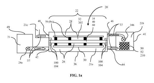
Electrolytic system 20 illustrates an embodiment of a system to treat
contaminated water
21, as shown in FIG. la. The electrolytic system 20 may be used to remove
negative ion species,
such as nitrates and phosphates. It may also be used to remove molecules of
high molecular
weight from contaminated water. It may also be used to remove arsenic and such
biological
materials as bacteria, proteins and DNA.
Electrolytic system 20 includes electrolytic cell 22 which includes anode
chamber 26,
cathode chamber 28, anode 30, cathode 32 and membrane 34, all enclosed in
containment tank
36, as shown in FIGS. la, lb and 2a, 2b. Anode 30 resides within anode chamber
26. Cathode
32 resides within cathode chamber 28. Membrane 34 is located within
electrolytic cell 22
between anode chamber 26 and cathode chamber 28. Membrane 34 is positioned in
electrolytic
cell 22 to maintain a pH difference between anode chamber 26 and cathode
chamber 28 when a
voltage is applied between anode 30 and cathode 32. Membrane 34 is supported
by membrane
assembly 40. Membrane 34 and membrane assembly 40 define the boundary between
anode
chamber 26 and cathode chamber 28. In one embodiment, electrolytic cell 22 is
open to the
atmosphere, facilitating fluid flow and equal pressures and water levels in
cathode and anode
chambers and venting of gases produced in the process.
In one embodiment, electrolytic cell containment tank 36 and associated inlet
and outlet
piping, valves, and tanks, are made of a highly inert material, such as
polypropylene. They may
also be made of other thermoplastics.
Contaminated water 21 for treatment is provided with hydrogen ions at anode 30
and
hydroxyl ions at cathode 32 when a voltage is applied, as shown in FIG. lb.
Thus, contaminated
water 21 is electrolytically made acidic in the anode chamber and basic in the
cathode chamber.
Flow directing device 24b is connected to direct acidic contaminated water 21a
from anode
8
WO 2013/002813 CA 02807813 2013-02-07PCT/US2011/046978
chamber 26 to holding tank 41 and then to cathode chamber 28, as shown by flow
direction
arrows 37. As the number of hydrogen ions generated in the anode chamber
equals the number
of hydroxyl ions generated in the cathode chamber the water emerging from
cathode chamber
28 has a pH equal to that of the water that entered the anode chamber.
Electrolytic system 20 may include just a single electrolytic cell 22, as
shown in FIG. la
or it may include multiple electrolytic cells 22', as shown in FIG. 3. Anode
chamber 26 includes
anode chamber inlet 42 and anode chamber outlet 44. Cathode chamber 28
includes cathode
chamber inlet 46 and cathode chamber outlet 48. At least one flow directing
device 24a, 24b is
provided in cooperation with electrolytic cell 22 to move water into and
through electrolytic
system 20. Flow directing device 24a, 24b may be a pump. Alternatively, flow
directing device
24a may be a flow mechanism that works by gravity feed.
Contaminated water 21 for treatment in electrolytic system 20 may enter and be
held in
inlet reservoir 49, as shown in FIG. la. Contaminated water 21 then flows
through anode
chamber inlet 42 and enters anode chamber 26. In anode chamber 26 some of the
water reacts at
anode 30 to produce hydrogen ions that acidify contaminated water 21, as shown
in FIG. lb.
Acidified contaminated water 21a exits anode chamber 26 through anode chamber
outlet 44 and
is directed to enter holding tank 41 which is provided inline between anode
chamber outlet 44
and cathode chamber inlet 46. In certain embodiments, filter 47 is used in
between anode
chamber outlet 44 and holding tank 41 to remove certain by-products of
reactions in anode
chamber 26 that could interfere with reactions that occur in holding tank 41
and/or in cathode
chamber 28, as further described herein below and illustrated in FIG. 11b.
Holding tank 41 and
flow directing device 24b aid in equalizing the contaminated water level
between anode
chamber 26 and cathode chamber 28. With equalized water levels fluids on both
sides of
membrane 34 will be at equal pressure and the only force driving material
across membrane 34
will be concentration gradients.
In one embodiment, a metal, such as metallic aluminum 50 or metallic iron 52
is
provided in holding tank 41, and acidified contaminated water 21a from anode
chamber 26
dissolves some of metallic aluminum 50 or metallic iron 52, providing aluminum
ions or iron
ions in contaminated water 21b.
9
WO 2013/002813 In the embodiment with aluminum 50, aluminum ion containing
contaminated water 21b CA 02807813 2013-02-07
PCT/US2011/046978
is then treated in cathode chamber 28 to remove negative ion species, such as
nitrates, and to
agglomerate molecules of high molecular weight and other negative ion species,
such as
phosphates and chlorides, that may have been present in entering contaminated
water 21, as
shown in FIG. ha. The high molecular weight material, phosphates, chlorides,
and other
unwanted species agglomerate onto aluminum hydroxide particles that form in
cathode chamber
28 from the dissolved aluminum ions reacting with hydroxyl ions formed at
cathode 32.
Agglomerated particle containing water 21c then exits cathode chamber 28
through cathode
chamber outlet 48. The phosphates, chlorides, and high molecular weight
particles agglomerated
on aluminum hydroxide particles are then filtered out of the aqueous stream,
to provide a
discharge of cleaned water 21d.
Alternative configurations for anode 30, cathode 32 and membrane 34 are shown
in FIG.
2a and 2b. In one embodiment, a fixed, uniform distance is provided between
surface 57a of
anode 30 and surface 57b of cathode 32, as conductivity between anode 30 and
cathode 32 is
directly proportional to the distance between them. In one embodiment, anode
30 and cathode
32 are mounted about an inch apart. This space between anode 30 and cathode 32
may be set by
dielectric spacers 56, which span between anode 30 and membrane frame 60 and
between
cathode 32 and membrane frame 60. The exact number, form and location of
spacers 56 may
vary by design.
In one embodiment, anode 30', cathode 32' and membrane 34 are oriented tilted
from the
vertical, as shown in FIG. 2b. The tilted array allows acceleration of fluids
as impelled by
hydrogen bubbles rising in contaminated water 21b across the surface of
cathode 32'. The array
structure may include two, five, ten, or any other number of anode and cathode
plates.
In one embodiment, electrolytic system 20 includes multiple electrolytic cells
22
arranged in parallel to process larger volumes of contaminated water. One way
to accomplish
this is to provide multiple electrolytic cells 22 of FIG. la and to provide
plumbing that divides
the incoming stream of contaminated water so a portion goes to each cell 22.
Each cell can have
its own holding tank 41 as shown in FIG. la. Alternatively the discharges from
all the anode
chambers 26 can be combined in a single holding tank. Plumbing can also
combine the
discharges of water from each of the separate cathode chambers to provide a
single discharge.
10
WO 2013/002813 Level sensors 58 may be positioned on each side of membrane 34.
A controller can use CA 02807813 2013-02-07
PCT/US2011/046978
output of level sensors 58 to control operation of flow directing device 24a,
24b to ensure that
water level on each side of membrane 34 is the same.
In another embodiment, the multiple electrolytic cells 70 are included in one
container
72, as shown in FIG. 3. In one embodiment of this approach each of
electrolytic cells 70 is 4-
feet wide, 12-feet long and 8-feet high. These dimensions may be varied
substantially without
impacting the effectiveness of the system. Source of contaminated water 21 is
connected
through intake reservoir 49 to multiple electrolytic cells 70. Plumbing 74
divides incoming
stream of contaminated water 21 so a portion of contaminated water 21 goes to
each anode
chamber 76 of the four cells 70 illustratively shown in FIG. 3. More or fewer
cells can be
included in such a multiple electrolytic cell. In this example, plumbing 78
from the four cells
combines the flow from the three anode chamber outlets to single holding tank
41. Plumbing 80
divides outflow from single holding tank 41so a portion goes to each cathode
chamber 82 of the
four electrolytic cells 70.
The four electrolytic cells 70 are arranged so anode chamber 76 of one cell is
adjacent
anode chamber 76 of the next cell and cathode chamber 82 of one cell is
adjacent cathode
chamber 82 of the next cell. Thus, cells 70 each have their own membrane 34
but cells 70 share
anode chambers 76 and share cathode chambers 82. In another embodiment,
adjacent cells could
share anode 30 and cathode 32, 202, substantially reducing the number of
electrode plates in
electrolytic cell 22'.
A single level sensor 58 may be positioned on each side of one membrane 34 of
the
multiple cell arrangement of FIG. 3 since the level in all anode chambers 76
should be the same
and the level in all cathode chambers 82 should be the same. As with the
single cell shown in
FIG. la, a controller can use output of level sensor 58 to control operation
of flow directing
device 24a, 24b to ensure that level on each side of membrane 34 is the same.
In one embodiment, anode chamber inlet 42 provides contaminated water 21
entering
from the top of anode chamber 26 and anode chamber outlet 44 provides
contaminated water 21
exiting at the bottom of the anode chamber 26, as shown in FIG. 4. In one
embodiment, cathode
chamber 32 provides contaminated water 21 entering through cathode chamber
inlet 46 at the
11
WO 2013/002813 CA 02807813 2013-02-07PCT/US2011/046978
bottom of cathode chamber 32 and contaminated water 21 exiting cathode chamber
outlet 48
from the top of the cathode chamber 32, as shown in FIG. 5.
A more detailed illustration of the configuration of anode 30 in anode chamber
26 is
shown in FIG. 4. This anode configuration is common for both the single cell
design of FIG. la
and the multi-cell design of FIG. 3; however, the exact sizing, shape and
orientation may be
different depending on the exact electrolytic cell design. Anode 30 may be
formed from
expanded metal, a metal structure similar to a screen, as a way of mitigating
cost; however, from
a functional standpoint anode 30 may also be a solid piece. Anode 30 may be
fabricated of
titanium (Ti) with an outer surface layer of sputtered iridium oxide (Ir02).
The use of 1r02 favors
the release of oxygen from oxygenated species, such as water, and disfavors
the release of
chlorine from chloride ions in the water. The iridium oxide acts as a
catalyst, lowering the
barrier to the reaction of oxygenated species without lowering the barrier to
the reaction of
chloride ions. However, if the current density at anode 30 is sufficiently
high, this will facilitate
reaching or exceeding the barrier height of chloride ions and generating
chlorine gas. This
current density is 5 amps/ft2. Regulating the power supply to under 5 amps/ft2
avoids chlorine
gas production. The length and width of each individual titanium anode with
the iridium oxide
coating may vary. In one embodiment, the thickness is .030"-.040," a thickness
that is available
as a standard commercial product.
A more detailed illustration of the configuration of cathode 32 in cathode
chamber 28 is
shown in FIG. 5. This cathode configuration is common to both the single cell
design of FIG. la
and the multi-cell design of FIG. 3. While a rectangular shape is shown, the
exact sizing, shape
and orientation may be different depending on the exact electrolytic cell
design. Cathode 32 is
mounted so there will be sufficient clearance over the top and under the
bottom of the cathode
so that contaminated water 2 lb may circulate freely.
In one embodiment in which nitrate ions are to be reduced to nitrogen gas by
introducing
contaminated water 21 into cathode chamber 28 first, cathode 32 is a plate
having a surface that
includes a metal such as titanium, yttrium, zirconium, hafnium, niobium,
tantalum, aluminum
and tungsten. These metals are known as "valve metals." When a cathode plate
formed from one
or more of the valve metals is subjected to air oxidation, the valve metal
builds up an irreducible
oxide coating on the metal surface of the plate. Particularly for titanium
this oxide has a
12
WO 2013/002813 CA 02807813 2013-02-07PCT/US2011/046978
structure that facilitates reduction of nitrates to nitrogen gas and water and
inhibits competing
reactions.
In one embodiment, cathode 32 is made of titanium 0.030 to 0.040 inches in
thickness, a
thickness that is available as a standard commercial product. The titanium is
air oxidized at 6000
C for ten minutes and then allowed to air cool to provide a uniform surface
layer of titanium
dioxide (TiO2) across the entire cathode. The length and width of each
individual cathode may
vary. In other embodiments, cathode 32 is fabricated of a metal, such as
copper, steel, monel,
and stainless steel with a thickness in the range of 0.030 to 0.040 inches. In
one embodiment,
anode and cathode were both rectangular with the same dimensions. Spacing was
1 inch
between anode 30 and cathode 32, and membrane 34 was half way in between.
Anode 30 was
fabricated of titanium and cathode 32 was fabricated of stainless steel, each
with a thickness of
.032 inches and assembled as four uniform sized rectangular pieces aggregating
36 inches in
length and 26 inches in width. Dimensions for cathode can be different from
dimensions of
anode and dimensions can be scaled for particular applications.
A more detailed illustration of the configuration of membrane 34 and membrane
assembly 40 is shown in FIGS. 6a and 6b. This membrane configuration is common
to both the
single cell design of FIG. la and the multi-cell design of FIG. 3. While a
rectangular shape is
shown the exact sizing, shape and orientation may be different depending on
the shape of the
exact electrolytic cell. In one embodiment, membrane 34 separating anode
chamber 26 and
cathode chamber 28 has a pore size of 0.5 micron +/- 5% a structure that is
suitable to allow
conductivity-driven transfers of ionic species in the water including Cat, Mg
2+, SO4 2-, HCO3,
C032-, Fe, etc. allowing electrical neutrality while preventing un-ionized
contaminated water
21 and particulates from passing through the membrane's pores. 1-1 and OH-
are generated at the
electrodes much faster than these species transit through the membrane,
allowing the pH
difference to develop without the addition of acidic or basic materials.
In one embodiment, membrane 34 has a pore size that is sufficiently large to
allow
electrically driven ion transfer, but sufficiently small to maintain the
required pH difference. In
one embodiment, the porous material of membrane 34 has pores with an average
pore size of
less than one micron, for example, pore size of about 0.5 microns. The average
pore size is
determined by using a standard bubble point measurement technique. Pore sizes
other than 0.5
micron, with a variation in size of about +/-5%, equivalent to variation of +/-
.025 microns, can
13
WO 2013/002813 CA 02807813 2013-02-07PCT/US2011/046978
be used. For example, membrane 34 can have pores with an average pore size in
the range from
0.5 to 10 micrometers with a variation of +/- 5% of the average pore size.
Larger pore sizes,
such as up to 50 micrometers, might also be used for some applications. One
material that can
be used for membrane 34 is polytetrafluoroethylene (PTFE). PTFE is chemically
inert to the
species contained within the water to be treated and can be fabricated with
the desired pore size
and distribution. Gore-Tex film, manufactured by W. L. Gore and Associates,
is one porous
material for membrane 34 that can be used. Number 2 GoreselectO and Primerae
are
commercial products that can be used.
Membrane 34 is supported between two halves of membrane frame 60 that are
fastened
together by fasteners 94, as shown in FIG. 6b. Gasket material 95, fabricated
of a material such
as neoprene, that is chemically resistant or impervious to the chemistry and
range of pH levels
of the contaminated water, may be sandwiched between membrane 34 and the
halves of
membrane frame 60 to ensure a proper seal, as shown in FIG. 6a. Membrane frame
60 is made
of polypropylene or another thermoplastic material that is impervious to the
range of pH that it
is subjected to. A lattice structure of polypropylene slats 96 helps reinforce
membrane 34 within
window 98 of membrane frame 60.
FIG. 7 shows how each end of membrane frame assembly 40 is supported within
containment tank 36. Support elements 100 on containment tank walls 102 and
containment
tank bottom 103, as shown in FIGS. 4, 5, and 7, create channel 104 extending
down both sides
of containment tank 36 and across the bottom of the tank. Within channel 104
are one or more
sealing elements, such as 0-ring gasket 106. Membrane frame assembly 40 is
inserted to slide
into slot 104 which holds membrane frame assembly 40 and forms a seal by
compressing
sealing elements 106. Other configurations are possible.
In one embodiment, the ability to maintain an equal pressure on either side of
membrane
34 is provided with pressure control system 110, as shown in FIGS. 8-9.
Pressure control system
110 may be used with single electrolytic cell 22 of FIGS. la, 8, multiple
electrolytic cell 22' of
FIG. 3, or some other variation of those electrolytic cells. Pressure control
system 110 maintains
equal pressure on both sides of membrane 34 so that a pressure difference does
not drive
contaminated water 21 across membrane 34. Membrane 34 maintains a substantial
pH
difference restricted only by electrically driven ionic transport that occurs
across membrane 34.
Membrane 34 provides that contaminated water 21 follows the path shown by flow
direction
14
CA 02807813 2013-02-07
WO 2013/002813 PCT/US2011/046978
arrows 37, maximizing the efficiency of electrolytic system 22. If significant
pressure driven
flow of water occurs across membrane 34, efficiency goes down as pH difference
is reduced and
reactions are slowed.
Pressure control system 110 includes pressure control unit 112 that receives
input from
water level sensors 114a, 114b, 114c and provides signals to control operation
of flow directing
devices 24a, 24b. Flow directing device 24a and 24b may each be a pump.
Alternatively, flow
directing device 24a could be a flow mechanism that works by gravity feed and
includes flow
restrictors. Water level sensor 114a monitors the level of contaminated water
21a in anode
chamber 26, water level sensor 114b monitors the level of contaminated water
21b in holding
tank 41, and water level sensor 114c monitors the level of contaminated water
21b in cathode
chamber 28. Pressure control unit 112 monitors levels of contaminated water
21, 21a, 21b,
within anode chamber 26 and cathode chamber 28, as well as holding tank 41,
and determines
where flow needs to occur to equalize level across membrane 34. If a
difference in level is found
pressure control unit 112 sends a signal to increase or decrease flow at flow
directing device
24a, 24b. Equalizing level equalizes pressure across membrane 34. In
embodiments that include
filter 47 between anode chamber 26 and holding tank 41, such as shown in FIG.
11b, the
operation of filter 47 and surge tank 140 are coordinated with the pressure
control system 110 as
further described herein below.
In one embodiment, flow directing devices 24a and 24b have the same volume
pumping
capacity and run at the same volume rate so levels in anode chamber 26 and
cathode chamber 28
should remain approximately equal. In one embodiment, the contaminated water
level
difference tolerance on either side of membrane 34 is within 1/2". If the
level measurement on
one side of membrane 34 is found to be different from the level measurement on
the other side
by more than this tolerance, then control unit 112 sends a signal to adjust
flow rate of either
flow directing device 24a, 24b.
Applicants found that membrane 34 allowed maintenance of a pH difference of at
least 6
pH units in the contaminated water between anode chamber 26 and cathode
chamber 28 when a
voltage sufficient to electrolyze water was applied between anode 30 and
cathode 32 without
flow from anode chamber to cathode chamber. Voltages in the range from 10 to
17 volts were
used. The range from 12 to 15 volts was found to provide good results. The
current was in the
range from 10 to 20 amperes for electrodes having an area of 7 ft2. The
temperature was in the
15
WO 2013/002813 CA 02807813 2013-02-07PCT/US2011/046978
range from 10 C to 25 C, varying with the season. Flow was in the range from
1 to 2 gallons
per minute. The electrolytic cell used in the experiment had a volume of 62
gallons. The voltage
used varied with the conductivity of the water. In one static experiment,
without flow, pH was 2
in anode chamber 26 and 10 in cathode chamber 28, a difference of 8 pH units.
Applicants found that they could measure pH in a single location to
characterize
functioning of the system. In one embodiment, pH control unit 120 is connected
to receive data
from pH sensor 122, as shown in FIG. 10. pH control unit 120 and pH sensor 122
can be
included in the single cell embodiment of FIG. la or a multiple electrolytic
cell embodiment,
such as that of FIG. 3, or some other variation of those electrolytic cells.
pH control unit 120 can
have its own power supply or it can be connected to receive power from DC
power control unit
124. pH sensor 122 may be a commercial pH sensor such as sensor made by
Sensorex, Garden
Grove, CA, part number S650CD.
In one embodiment, pH sensor 122 is located within holding tank 41 and
measures pH of
aluminum- or iron-containing contaminated water 21b in holding tank 41. pH
sensor 122 is
located outside of electrolytic cell 22 so that the electric field generated
within the electrolytic
cell does not interfere with functioning of pH sensor 122. The output signal
of pH sensor 122 is
typically in the range of 4mA to 20mA and is in direct proportion to pH
readings, with higher
current correlating to higher pH.
DC power control unit 124 is electrically connected to anode 30 and cathode 32
to
provide a voltage there-between sufficient to electrolyze water, generating
oxygen and hydrogen
ions at the anode and generating hydroxyl ions at the cathode. pH control unit
120 translates the
pH reading from pH sensor 122 to a signal to step-up or step-down voltage
applied by DC
power control unit 124 across anode and cathode. By restricting flow of
hydrogen and hydroxyl
ions between anode chamber 26 and cathode chamber 28 membrane 34 produces the
substantial
pH difference between anode chamber 26 and cathode chamber 28 and provides
highly acidic
contaminated water 21a exiting anode chamber 26 that can dissolve sufficient
solid aluminum
50 or iron 52 to support agglomeration of high molecular weight molecules.
Other contaminants
that may have been in entering contaminated water 21 also agglomerate on the
aluminum
hydroxide or iron hydrous oxide, including nitrates, phosphates, arsenates and
other negative ion
species. As described herein above, membrane 34 has a pore size sufficiently
large to allow
restricted electrically driven ion transfer to occur, but sufficiently small
to limit mass transfer of
16
WO 2013/002813 CA 02807813 2013-02-07PCT/US2011/046978
contaminated water 21 and maintain a significant pH difference. In operation,
applicants found
that the applied voltage of 10 to 15 volts provided a pH of less than or equal
to 4-pH units in
anode chamber 26 and greater than or equal to 10-pH units at cathode 32 before
flow initiation,
or a pH difference of 6 pH units. Membrane 34 can support a pH difference of
approximately 9
pH units when a higher voltage is applied by DC power supply 124 to produce a
pH of less than
or equal to 2-pH units at anode 30 and greater than or equal to 11-pH units at
cathode 32 in a
static experiment.
In one embodiment, electrolytic cell 22, 22' of FIG. la, FIG. 3 and FIG. 13a
can be used
to reduce nitrate to nitrogen gas. Catalyzed by the valve metal surface of
cathode 32, nitrates in
contaminated water 21, 21a undergo a series of reactions in contaminated water
21a, 21b and
with electrons provided at cathode 32 according to equation 1 to generate
nitrogen gas, as shown
in box 138 of FIG. 14b.
2NO3- + 12H+ + 10e- = N2(g) + 6H20 at cathode (1)
Nitrogen gas escapes into the air while water generated in this reaction
merges with
contaminated water with nitrates removed 21c. Contaminated water 21c with
nitrates removed is
then directed out of cathode chamber 28 via cathode chamber outlet 48.
In a variation on this embodiment, the flow of water in electrolytic cell 22,
22' is
reversed to achieve the same effect of reducing the nitrate to nitrogen gas,
as depicted in FIG.
13b. Nitrate-contaminated water 21 is directed by flow directing device 24a to
cathode chamber
28 through cathode chamber inlet 46. Nitrate-contaminated water 21 reacts at
cathode 32,
elevating the pH of nitrate-contaminated water 21 to a level in the range from
11 to 12. A highly
complex series of transitory reactions occurs in the high pH water, resulting
in the nitrate being
reduced to nitrogen gas which is vented to the atmosphere.
While the sequence and nature of the reactions involved have not been fully
characterized, the effectiveness of an electrochemical process to reduce
nitrate to nitrite,
nitrogen gas, and ammonia, has been described in a paper by Dash and
Chaudhari,
"Electrochemical denitrification of simulated ground water," Centre for
Environmental Science
and Engineering, Indian Institute of Technology Bombay, Powai, Mumbai, India,
July 2005,
incorporated herein by reference.
17
CA 02807813 2013-02-07
WO 2013/002813 PCT/US2011/046978
Highly alkaline water with nitrate removed 21y exits cathode chamber 28
through
cathode chamber outlet 48 and into holding tank 41 where it is directed by
flow directing device
24b to anode chamber inlet 42. In anode chamber 26, the pH of highly alkaline
nitrate-free water
21y is lowered and nitrate-free water 21z with substantially the same pH as
the contaminated
water entering cathode chamber 28, which is approximately neutral pH, flows
out of anode
chamber 26 through the anode chamber outlet 44, where it is discharged as
nitrate-free water
21z. While nitrates have been removed, other contaminants that were in
entering nitrate-
contaminated water 21 may remain in discharged nitrate-free water 21z.
Because calcium ions in highly alkaline contaminated water 21y would coat the
catalytic
surface of cathode 32, interfering with the reaction to remove nitrate,
removing calcium ions
before using electrolytic cell 22, 22' is desirable. Calcium ions may be
removed using
complexation, chemical precipitation, or ion exchange. For applications, such
as removing
nitrate from calcium-free water used for washing semiconductor wafers after a
nitric acid
treatment, electrolytic cell 22, 22' can be used directly.
In one embodiment, an electrolytic cell is used for removing molecules of high
molecular weight, as described herein below, followed by a second electrolytic
cell, as shown in
FIGS. 13a-13b, which can be used for removing nitrates by gasification. In one
embodiment, the
first electrolytic cell for removing the molecules of high molecular weight
has contaminated
water first entering its anode chamber while the second electrolytic cell for
removing nitrates
has the contaminated water first entering its cathode chamber.
With metallic aluminum 50 or iron 52 provided in holding tank 41, electrolytic
system
20 of FIG. la, FIG. 3 and FIG. ha can be used to remove molecules of high
molecular weight
from contaminated water 21. Molecules of high molecular weight are defined as
molecules
having a molecular weight of 200 or higher. Aluminum ions generated from
dissolution of
metallic aluminum 50 in acidic contaminated water 2 lb from anode chamber 26
react at cathode
32 to produce aluminum hydroxide that agglomerates high molecular weight
molecules in
contaminated water 21c. Iron ions generated from dissolution of metallic iron
52 in acidic
contaminated water 2 lb from anode chamber 26 react at cathode 32 to produce
ferric hydrous
oxide that agglomerates high molecular weight molecules in contaminated water
21c. Other
materials, such as phosphates, chlorides, and other negative ion species will
also agglomerate
onto the aluminum hydroxide and/or the ferric hydrous oxide. Filter 54 in the
discharge line
18
WO 2013/002813 CA 02807813 2013-02-07PCT/US2011/046978
filters out the aluminum hydroxide and/or the ferric hydrous oxide with its
agglomerated
materials from contaminated water 21c, leaving clean water 21d flowing out of
filter 54.
Typical molecules of high molecular weight include organics, pharmaceuticals,
detergents, disinfectants, protein fragments and human and animal waste
byproducts.
In anode chamber 26 some of contaminated water 21 reacts at anode 30 to
generate
oxygen gas that escapes, hydrogen ions in the water, and electrons that flow
in the anode to DC
power supply 124 according to equation 2 and as shown in box 130 in the flow
chart in FIG.
14a.
6H20 = 12H+ + 302(,) + 12e- at anode (2)
Fluid containing the hydrogen ions transits out of anode chamber 26 to holding
tank 41,
as shown in box 132, where it encounters solid aluminum 50. Metallic aluminum
50 may be any
aluminum material that has a high surface area. Some of the hydrogen ions
react with metallic
aluminum 50 to generate aluminum ions and hydrogen gas according to equation 3
and as
shown in box 134 in FIG. 14a.
4A1(s) + 12H+ = 4A13+ + 6H2(,) in holding tank (3)
Metallic aluminum 50 can be provided in holding tank 41 or it can be provided
elsewhere in the system between anode 30 and cathode 32, as long as metallic
aluminum 50 is
immersed in acidic contaminated water 21a for a sufficient time to react with
the hydrogen ions
to produce aluminum ions. As acidic water from anode chamber 26 has a longer
residence time
in holding tank 41, locating metallic aluminum 50 there is likely to produce
sufficient aluminum
ions in contaminated water 2 lb.
From holding tank 41 aluminum ion containing contaminated water 21b flows into
cathode chamber 28, as shown in box 136.
Meanwhile, in cathode chamber 28 some of contaminated water 2 lb reacts,
taking
electrons supplied by cathode 32 from DC power supply 124 to generate hydrogen
gas, that
escapes, and providing hydroxyl ions in contaminated water 21c according to
equation 4, and
19
WO 2013/002813 CA 02807813 2013-02-07PCT/US2011/046978
as shown in box 138. Alternatively the hydrogen gas may be collected and
otherwise used later
as a fuel.
12H20 + 12e = 6H2(,) + 120H- at cathode (4)
In addition, aluminum ions in contaminated water 2 lb, generated in holding
tank 41
according to equation 3, react at cathode 32 with hydroxyl ions to form
aluminum hydroxide
according to equation 5.
4A13+ + 120H- = 4A1(OH)3(s) in cathode chamber (5)
Th aluminum hydroxide acts as an agglomerating material for high molecular
weight
molecules in solution in contaminated water 21b. High molecular weight
molecules adsorb onto
the aluminum hydroxide which then precipitate as agglomerated particles.
Contaminated water 21c with agglomerated high molecular weight material is
then
directed out of cathode chamber 28 via cathode chamber outlet 48 . The
agglomerated particles
have sufficient size to be removed from the contaminated water by filter 54,
leaving water clean
of high molecular weight material 21d. In one embodiment, applicants used a
commercial bag
filter, Rosedale model 8, from Rosedale Products, Inc., Ann Arbor, Michigan,
to remove the
agglomerated particles.
As contaminated water 2 lb transits the cathode chamber 28, the flow of
hydrogen ions
and aluminum ions with contaminated water 2 lb plus the flow of electrons
through membrane
34 serves to neutralize the pH of the contaminated water 21c in cathode
chamber 28, so the pH
of the contaminated water 21c at cathode chamber outlet 48 and the pH of clean
water leaving
filter 54 is the same as the pH of entering contaminated water 21, which is
approximately 7.0
pH units.
In another embodiment, metallic iron 52 is provided in holding tank 41, and
acidified
contaminated water 21a from anode chamber 26, according to equation 6,
dissolves some of
metallic iron 52, providing iron ions in contaminated water 2 lb, according to
equations 7 and 8
and as shown in FIG. lla and the flow chart in FIG. 15.
20
WO 2013/002813 6H20 = 12H+ + 302(,) + 12e-
CA 02807813 2013-02-07
at anode (6)
PCT/US2011/046978
The electrons go to the anode providing electric current in the circuit. The
02(g) vents to
the atmosphere or remains in solution. Most hydrogen ions flow out of anode
chamber 26 along
with the water contaminated with heavy molecules and negative ion species,
typically at
approximately pH 2, to holding tank 41, while a few of the hydrogen ions
migrate through the
membrane and enter cathode chamber 28.
4Fe(s) + 8H+ = 4Fe2+ + 4H2(g)
in holding tank (7)
4Fe2+ + 02(g) + 4H+ = 4Fe" + 2H20
in holding tank (8)
In holding tank 41 metallic iron 52 reacts with hydrogen ions entering from
anode
chamber 26, as shown in equations 7 and 8. The iron ions in solution flow with
the water
contaminated with heavy molecules and negative ion species and remaining
hydrogen ions to
cathode chamber 28 while the H2(g) either vents to the atmosphere or combines
with oxygen gas
to form water.
Iron is not sufficiently active a metal to consume all the hydrogen ions;
thus, the solution
remains acidic, typically at approximately pH 3.5, facilitating keeping Fe'
ions in solution for
further reaction with hydroxyl ions formed at cathode 32. Contaminated water 2
lb containing
these Fe' ions is treated in cathode chamber 28 to remove negative ion
species, such as nitrates,
phosphates, and arsenate and to agglomerate molecules of high molecular weight
and other
negative ion species, such as chlorides, that may have been present in
entering contaminated
water 21. The high molecular weight material, nitrates, phosphates, arsenate,
chlorides, and
other unwanted species agglomerate onto iron hydrous oxide particles that form
in cathode
chamber 28 from the dissolved iron ions reacting with hydroxyl ions formed at
cathode 32. Two
reactions occur in cathode chamber 28.
First, the dissociation of water with electrons produced at cathode 32 forms
hydroxyl
ions and hydrogen gas according to equation 9, as shown in FIG. lla and in the
flow chart in
FIG. 15:
12H20 + 12e = 6H2(g) + 120H-
at cathode (9)
21
WO 2013/002813 The H2(,) vents to the atmosphere while Fe' ions in
contaminated water 2 lb combine in CA 02807813 2013-02-07
PCT/US2011/046978
the second reaction at cathode 32 with hydroxyl ions formed there according to
equation 9 to
form iron hydrous oxide according to equation 10:
4Fe3+ + 120H- = 4Fe(OH)3(s)
in cathode chamber (10)
The nitrates, phosphates, arsenate, chlorides, and high molecular weight
molecules
agglomerate on the iron hydrous oxide Fe(OH)3(s) particles. The agglomerated
particles
precipitate out of water 21c. Water 21c with agglomerated particles exits
cathode chamber 28
through cathode chamber outlet 48. The nitrates, phosphates, arsenate,
chlorides, and high
molecular weight molecules agglomerated on iron hydrous oxide particles are
then filtered out
of the aqueous stream using filter 54, as shown in FIG. lla to provide a
discharge of cleaned
water 21d that is back to substantially the same pH as the contaminated water
entering anode
chamber 26, which is approximately neutral pH.
Applicants found that the in situ generation of iron hydrous oxide by
dissolution of iron
in acidified contaminated water 21a from anode chamber 26 followed by reaction
of the iron
ions so formed with hydroxyl ions at cathode 32 produced a finely divided
entity that was
particularly effective at removing the above listed unwanted contaminants from
the water.
Applicant filtered the effluent with filter paper and visually observed the
fine iron hydrous oxide
particle size. The interaction between oxy-anions and iron hydrous oxide has
been described in
the book, "Anion Interactions with Freshly Prepared Hydrous Iron Oxides," by
J. B Harrison
and V. E Berkheiser, Clays and Clay Minerals, Vol. 30, No. 2, pages 97-102,
1982),
incorporated herein by reference.
In this embodiment, because nitrates are removed by surface chemical reaction
and
adsorption, rather than reduction at the cathode, a valve metal is not needed
in the cathode as a
catalyst. The expense of a valve metal surface for the cathode is thus avoided
in this
embodiment. Cathode 202 is fabricated of a metal, such as stainless steel.
Nickel, copper, silver
or other conductive metals can be used for cathode 202.
In addition, since reaction of nitrates at the cathode is avoided, techniques
to enhance
that reaction, such as cathode tilting, are avoided, freeing space for more
electrodes per tank.
22
CA 02807813 2013-02-07
WO 2013/002813 PCT/US2011/046978
Also, in this embodiment, because nitrates are removed by surface chemical
reaction and
adsorption on the iron hydrous oxide particles, rather than being reduced at
the cathode, less
electric current need be provided. Five electrons to reduce each nitrate ion
to nitrogen gas are
avoided in this process while 3 electrons are used to form each iron hydrous
oxide.
The current apparatus and method of removing nitrates and molecules of high
molecular
weight offer several advantages over bio-oxidative, chemical and past
electrolytic treatments of
water. The apparatus of the current patent application uses a much smaller
footprint that reduces
the physical size and cost of the treatment plant by a factor of between 5 and
10. In several
embodiments, the process effectively eliminates sludge byproduct and
unpleasant odors
generated by the bio-oxidative process. In several embodiments, no chemicals
are applied and
byproducts are mainly nitrogen, oxygen and hydrogen gases that may be freely
released to the
atmosphere or may be collected. The present patent application describes a
process that uses less
electricity than that described in the '873 patent. In use the process is
expected to use 1.1
kilowatt hours of electricity per 1000 gallons of water treated. At a cost of
10-cents per kilowatt
hour, the cost for electricity to treat 1000 gallons of water is therefore
about 11 cents. Cost for
facilities and labor should add a few more cents per 1000 gallons making the
total cost less than
half that of conventional techniques that are presently about 35-cents per
1000 gallons.
Applicant also found that the localized highly acidic condition at the anode
caused two
effects on biological materials, such as bacterial cells, that are in the
contaminated water: one is
protonation of proteins and protein fragments that may be present in
contaminated water; and
the other is hydrolysis of elements of the DNA of residual bacterial cells in
contaminated water,
breaking up the helical ribbons of their DNA, as shown in FIG. 16 and FIG. 17
respectively.
As described herein above, in the reaction at anode 30, entering water 21,
contaminated
with organic material, including proteins and protein fragments, becomes
highly acidic, with a
pH of approximately 2, by the hydrolysis of water releasing hydrogen ions, as
shown in equation
11.
2H20 = 4f1+ + 02(,) + 4e- at anode (11)
The hydrogen ions serve as a catalyst to protonate proteins of organic
materials in two
simultaneous ways: cleaving peptide bonds that hold the chain of amino acid
residues together
23
WO 2013/002813 CA 02807813 2013-02-07PCT/US2011/046978
in the primary structure that forms proteins, reducing the proteins to smaller
fragments or
individual amino acids as shown for the cleaving of a two-amino-acid peptide
in FIG. 16; and
breaking the hydrogen bonds in the secondary structure that gives proteins
their configuration or
shape.
The peptides present at the start of the treatment are not truly dissolved
species. They are
hydrated structures that are suspended in the aqueous medium by virtue of
their conformation.
Disrupting this conformational balance by acid catalyzed hydrolysis produces
coagulation.
When exposed to substantially lowered pH, as in anode chamber 26, the protein
turns highly
positive, leading to intramolecular repulsion great enough to break weak
hydrogen bonds in the
protein's secondary structure and cause unfolding of the protein. The
unfolding exposes
hydrophobic groups.
These alterations irreversibly disrupt the protein structure, inactivating
both biological
and mechanical properties. The resultant material forms insoluble coagulates
that are lighter
than water. Thus, the aggregated material rises to the surface of the water
where it can be
skimmed. The rising to the surface may be assisted by the oxygen bubbles
formed by the
dissociation of water of equation 11.
Further, in a separate reaction, hydrogen ions (H ) formed in equation 11 also
attack the
negative sites (0-) in the sugar-phosphate helical ribbons of DNA or RNA of
organisms, such as
bacteria, cleaving the bonds between the phosphate esters and the sugars,
fragmenting the
backbone of the DNA ribbons and releasing sugars and phosphates into the
water, as shown in
FIG. 17. Once released into the water, the phosphates and sugars are carried
on into holding tank
41 and from there to cathode chamber 28. In this hydrolysis reaction, the
hydrogen ions catalyze
the bond breaking and are not consumed. The fragmenting of the DNA backbone
merely
involves hydrolysis, or addition of a water molecule across the chemical bond.
Water is the only
consumable.
Applicant found that, when the supply of contaminated water 21 contained
sufficiently
high levels of biologic or organic material, the volume of residual aggregated
materials, protein
fragments and other organic waste flowing out of the anode chamber 26 would
gradually coat a
variety of surfaces downstream from the anode chamber, in particular the
aluminum 50 and/or
iron 52 in the holding tank 41. Such coating would cause an occlusion of
reactions described
24
WO 2013/002813 CA 02807813 2013-02-07PCT/US2011/046978
herein. In order to prevent such occlusion, applicant determined that skimming
and/or filtration
would remove such aggregated materials, protein fragments and other organic
waste to a degree
sufficient to prevent coating of downstream surfaces.
Applicant found that providing filter 47 positioned in line between anode
chamber outlet
44 and holding tank 41 removed the aggregated materials, protein fragments and
other organic
waste. As depicted in FIG. 11b, contaminated water 21a, laden with biological
waste, enters
surge tank 140 through surge tank inlet 142. Here contaminated water 21a is
maintained at water
level 143a while it is pumped out through surge tank outlet 144 by pump 24c to
filter 47. In
filter 47 the acid-aggregated materials, including protein fragments and other
organic waste, are
removed. The storage in surge tank 140 permits an interrupted flow of entering
contaminated
water 21 while allowing function of a back pulse feature. While pump 24c is
off and clean water
is back pulse provided to filter 47 to clean off debris collected on filter
47, water accumulates in
surge tank 140 to water level 143b. Then, when back pulsing is finished, pump
24c turns on and
the water in surge tank 140 returns to water level 143a.
In one embodiment, filter 47 is part of back-pulse filtration unit 146, 147 as
shown in
FIGS. 12a-12c. In this embodiment, contaminated water 21a with aggregated
materials, protein
fragments and other organic waste enters filter chamber 150 while pump 24c is
operating.
Contaminated water 21a is cyclically pushed by pump 24c into filter 47 mounted
on filter
mounting plate 152. In one embodiment, filter 47 uses sleeves of membrane
material 154 around
perforated pipe 156. Any other suitable means of structurally preventing
sleeves of membrane
material 154 from collapsing can be used. Filter 47 is sized to remove
aggregated materials,
protein fragments and other organic waste. In one embodiment, membrane
material 154 is PTFE
and has a pore size of 0.5 micrometers.
Back-pulse filtration unit 146 uses back pulse pump unit 148, as shown in FIG.
12a,
while back-pulse filtration unit 147 uses gravity, as shown in FIGS. 12b, 12c,
for back pressure.
Aggregated materials, protein fragments and other organic waste collect on
outer surface 158 of
membrane material 154 as the contaminated water 21a is pushed through filter
47 by pump 24c.
At intervals of time, such as every 10 or 20 minutes, pump 24c is turned off
and either back
pulse pump 157 or reverse gravity feed system 147 is activated to provide a
back pulse of
filtered water 21a in reverse direction through filter 47. This back pulse of
water 21a causes the
aggregated materials, protein fragments and other organic waste to release
from surface 158 of
25
CA 02807813 2013-02-07
WO 2013/002813 PCT/US2011/046978
membrane material 154 and fall into base 162 of filter chamber 150. Waste
valve 166 opens for
approximately 100 milliseconds during the period when pump 24c is off and
reverse water flow
is being applied. This allows aggregated materials, protein fragments and
other organic waste to
be discharged into waste collection system 168.
Back pulse pump unit 146 also includes back pulse pump 157, effluent shut-off
valve
160, and tank 149, all controlled and coordinated by control unit 112. Pump
24c and back pulse
pump unit 148, or gravity feed system 147, coordinated by control unit 112,
regulate water flow
direction during the filtration and filter cleaning processes. Filtered water
21a exits at water
discharge 170. For practical purposes, it is desirable for filter 47 to be
self-cleaning to prevent
accumulation of aggregated materials, protein fragments and other organic
waste and its
potential to clog filter media and mitigate or prevent flow of contaminated
water 21a.
Alternatively, filter 47 could be any other kind of filter that is capable of
removing unwanted
material with a particle size of 1 micrometer or larger.
Nitrates and ammonia are not generally found together in contaminated water.
If both
were present first the nitrates would be removed with iron, as described
herein above, then in a
separate reaction the ammonia would be removed with magnesium hydroxide, as
described
herein below.
Applicant found that ammonia contamination could be removed from the water
with the
provision of magnesium hydroxide 210 in holding tank 41, instead of iron or
aluminum, and
reaction with phosphate that may already be in the water either from acid
reaction with bacterial
DNA, as described herein above, or from other sources. As ammonia is a
breakdown product of
biological materials it is often found together with biologically derived
phosphates. The reaction
takes advantage of the presence of the phosphates and removes them too.
The acidic water 21a flowing out of anode chamber 26, as shown in FIG. la,
FIG. ha
and FIG.18, reacts in holding tank 41 with magnesium hydroxide 210 to produce
magnesium
ions Mg', as shown in equation 12.
2Mg(OH)2 + 4H+ = 2Mg' + 2H20 at anode (12)
26
WO 2013/002813 The Mg' ions in solution then flow with water 21b containing
phosphate and any CA 02807813 2013-02-07
PCT/US2011/046978
remaining hydrogen ions, into cathode chamber 28, as also shown in FIG. 18.
Hydroxyl ions
produced at cathode 202 react with remaining hydrogen ions to produce water
with a neutral pH,
and the ammonia reacts with magnesium and phosphate in this neutral water in
the cathode
chamber to form magnesium ammonium phosphate, as shown in equation 13,
2Mg' + 2NH4+ + 2(PO4)3- = 2MgNH4PO4
at cathode (13)
The magnesium ammonium phosphate precipitates out of solution and is filtered
out.
While the disclosed methods and systems have been shown and described in
connection
with illustrated embodiments, various changes may be made therein without
departing from the
spirit and scope of the invention as defined in the appended claims.
What is claimed is:
27