Note: Descriptions are shown in the official language in which they were submitted.
CA 02807882 2013-02-28
ABRASION RESISTANCE IN WELL FLUID WETTED ASSEMBLIES
BACKGROUND OF THE INVENTION
[001] 1. FIELD OF THE INVENTION
[002] Embodiments of the invention described herein pertain to the field of
well fluid wetted
assemblies.
[003] More particularly, but not by way of limitation, one or more embodiments
of the invention
enable abrasion resistance in well fluid wetted assemblies.
[004] 2. DESCRIPTION OF THE RELATED ART
[005] Fluids containing hydrocarbons, such as oil and natural gas, are often
located in
underground formations. In such situations, the oil or gas must be pumped to
the surface so that
it can be collected, separated, refined and sold. Many of these underground
for-nations also
contain well born solids, such as consolidated and unconsolidated sand. The
hydrocarbon laden
fluids must pass through the sand on their way to the pump intake, and
ultimately to the surface.
When this occurs, the hydrocarbon fluids carry the sand through pump
components. Such well-
born solids may have severe abrasive effects on the submersible pump
components and increase
the heat generated during use, since abrasive wear to the pump causes
inefficiency in its
operation. As a result, careful attention to fluid and pressure management in
submersible pump
systems is needed in order to improve the production of hydrocarbon laden
fluids from
subsurface formations.
[006] Currently available submersible pump systems are not appropriate for
some well
applications. Particularly, pump components used in oil or gas production
applications should be
exceptionally resistant to erosive wear. When a pump is used in an oil or gas
well, equipment
failure is especially costly as this can impede well production and replacing
parts is undesirable
since the equipment is deep in the ground. Care must be taken in cooling the
pump equipment
and avoiding the damage caused by abrasive materials in the produced well
fluid.
[007] In the case of an electric submersible pump (ESP), a failure of the pump
or any support
components in the pump assembly can be catastrophic as it means a delay in
well production and
having to remove the pump from the well for repairs. Downhole applications in
particular
require that ESP pumps be able to survive constant exposure to abrasive
materials in the well
1
CA 02807882 2013-02-28
fluid as well as the heat generated when the pump is in operation. A
submersible pump system
with improved thrust handling and radial support capabilities, such as an
improved ability to
withstand abrasion and heat, would be an advantage in all types of submersible
and non-
submersible assemblies.
[008] Currently available pump assemblies contain bearing surfaces. FIGs. 1A-
1C illustrate an
example of a "Mixed Flow" thrust bearing surface of the prior art. FIG. 1 A is
a top view of a
conventional stationary member. FIG. 1B is a cross section along line 1B-1B of
a conventional
stationary member. FIG. 1C is a perspective view of a conventional rotating
member. In
conventional assemblies, the rotating member of FIG. 1C is keyed to the shaft
of a submersible
pump and rotates with the shaft as fluid is pumped to the surface of a well.
The stationary
member of FIGs. 1A, 1B is attached to the wall of the diffuser of the
submersible pump and does
not rotate. Conventional designs are not well suited to withstand excessive
abrasion in pumping
systems or to keep the bearing surfaces cool. These shortcomings decrease the
longevity of the
pump components.
[009] Therefore, there is a need for better abrasion resistance in well fluid
wetted assemblies to
more readily withstand the effects of well-born solids and improve cooling
characteristics,
thereby improving the lifespan of the pump and pump components in submersible
pump
applications.
BRIEF SUMMARY OF THE INVENTION
[0010] One or more embodiments of the invention enable abrasion
resistance in well
fluid wetted assemblies.
[0011] Enhanced abrasion resistance in well fluid wetted assemblies
is described. The
bearing set of an illustrative embodiment may comprise a stationary member,
wherein the
stationary member further comprises a radial flute, sector flute and an axial
flute, and wherein
the radial flute and sector flute intersect with the axial flute; and a
rotating member, wherein the
rotating member is rotationally coupled with the stationary member, wherein
the rotating
member further comprises a thrust surface groove and a radial surface groove,
and wherein the
thrust surface groove intersects with the radial surface groove. In some
embodiments, the
stationary member comprises at least two radial flutes, wherein the radial
flutes create at least
two sectors and at least two sector flutes on the radial surface of the
stationary member. In
2
CA 02807882 2015-01-28
certain embodiments, the radial surface groove is a spiral groove. In some
embodiments the
stationary member of the present disclosure may be combined with a
conventional rotating
member of the prior art. In other embodiments, the rotating member of the
present disclosure
may be combined with a conventional stationary member of the prior art.
[0012] A
bearing for a submersible pump system comprises a radial flute and an axial
flute, wherein the radial flute intersects with the axial flute.
[0013]
An illustrative embodiment may comprise a method of enhancing abrasion
resistance of submersible assemblies, the method comprising pumping a
hydrocarbon laden fluid
from an underground formation to a surface location, wherein a pump component
comprises a
radial groove and an axial groove on a bearing surface, and wherein the radial
groove and the
axial groove intersect. In some embodiments, the pump component is the
rotating member of a
bearing set. In certain embodiments, the pump component is the stationary
member of a bearing
set. In some embodiments the pump component further comprises a submersible
pump. In other
embodiments, the pump component further comprises a submersible intake.
[0014] The bearing surface(s) of illustrative embodiments may be suitable
for a variety of
types of submersible stages known in the art for use in submersible pumps. For
example, mixed
flow submersible pump stages, as well as radial flow submersible pump stages,
may make use of
the enhanced bearing surface(s) of illustrative embodiments. Both these and
other submersible
stages suitable for use with an ESP system may benefit from the enhanced
bearings and method
of illustrative embodiments.
[0014A]
In one illustrative embodiment, a bearing set for a submersible pump system
includes a stationary member and a rotating member. The stationary member
includes a sector
flute. The rotating member is rotationally coupled with the stationary member.
The rotating
member further includes a thrust surface groove and a radial surface groove.
The thrust surface
groove intersects with the radial surface groove.
[0014B]
In another illustrative embodiment, a bearing for a submersible pump
includes a
stationary member, the stationary member including a radial flute, a sector
flute and an axial
flute. The radial flute intersects with the axial flute, and the sector flute
intersects with the radial
flute and the axial flute. The bearing also includes a rotating member
rotationally coupled with
the stationary member. The rotating member further includes a thrust surface
groove and a radial
surface groove, and the thrust surface groove intersects with the radial
surface groove.
3
CA 02807882 2015-01-28
[0014C]
In another illustrative embodiment, a system for enhancing the abrasion
resistance
of submersible assemblies includes a submersible pump. The submersible pump
further includes
a bearing set. The bearing set includes a stationary member and a rotating
member, the
stationary member includes an axial flute and a radial flute, and the axial
flute and radial flute
intersect. The submersible pump further includes a fluid hydrocarbon. The
fluid hydrocarbon
further includes a solid. The fluid hydrocarbon flows through the bearing set,
and the flutes are
configured to reduce abrasion on the bearing set.
[0014D]
In another illustrative embodiment, a method of enhancing the abrasion
resistance
of submersible assemblies includes pumping a fluid from an underground
formation to a surface
location. A pump assembly component includes a radial surface groove and a
thrust surface
groove, and the radial surface groove and thrust surface groove intersect.
[0014E]
In another illustrative embodiment, a system for enhancing the abrasion
resistance
of submersible assemblies includes a submersible pump for pumping a fluid
hydrocarbon from a
well. The submersible pump includes a stationary member of a bearing set. The
stationary
member includes an axial flute and a radial flute, and the axial flute and the
radial flute intersect.
The axial flute and the radial flute are configured to reduce abrasion from a
well-born-solid on
the bearing set.
[0014F]
In another illustrative embodiment, a system for pumping a hydrocarbon from
a
downhole well includes a submersible pump assembly component. The submersible
pump
assembly component includes a stationary member of a bearing set. The
stationary member
includes an axial flute and a radial flute, and the axial flute intersects the
radial flute at an
intersection. The axial flute, the radial flute and the intersection are
configured to guide a
pumped fluid through the flutes.
[0014G]
In another illustrative embodiment, a method of enhancing the abrasion
resistance
of submersible assemblies includes pumping a fluid from an underground
formation to a surface
location. A pump assembly component includes an axial flute and a radial
flute, and the axial
flute and the radial flute intersect.
[0015]
In further embodiments, features from specific embodiments may be combined
with features from other embodiments. For example, features from one
embodiment may be
combined with features from any of the other embodiments. In further
embodiments, additional
features may be added to the specific embodiments described herein.
3A
CA 02807882 2013-02-28
BRIEF DESCRIPTION OF THE DRAWINGS
[0016] The above and other aspects, features and advantages of
illustrative embodiments
of the invention will be more apparent from the following more particular
description thereof,
presented in conjunction with the following drawings wherein:
[0017] FIG. 1A illustrates a top view of a conventional stationary
bearing surface of the
prior art.
[0018] FIG. 1B illustrates a cross sectional view along line 1B-1B of
FIG. 1A of a
conventional stationary bearing surface of the prior art.
[0019] FIG. 1C illustrates a perspective view of a conventional rotating
member of the
prior art.
[0020] FIG. 2A illustrates a top view of an exemplary stationary
bearing surface of the
invention.
[0021] FIG. 2B illustrates a cross sectional view along line 2B-2B of
FIG. 2A of an
exemplary stationary bearing surface of an illustrative embodiment.
[0022] FIG. 3 illustrates a perspective view of an exemplary rotating
bearing surface of
an illustrative embodiment.
[0023] FIG. 4 illustrates one embodiment of an exemplary electric
submersible pump
(ESP) system for use in the system of an illustrative embodiment.
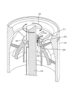
[0024] FIG. 5 illustrates a cross-sectional view along line 5-5 of FIG 4 of
one
embodiment of a diffuser of a submersible pump for use in the system of an
illustrative
embodiment.
[0025] While the invention is susceptible to various modifications
and alternative forms,
specific embodiments thereof are shown by way of example in the drawings and
may herein be
described in detail. The drawings may not be to scale. It should be
understood, however, that
the drawings and detailed description thereto are not intended to limit the
invention to the
particular form disclosed, but on the contrary, the intention is to cover all
modifications,
equivalents and alternatives falling within the scope of the present invention
as defined by the
appended claims.
4
CA 02807882 2013-02-28
DETAILED DESCRIPTION
[0026] Enhanced abrasion resistance for well fluid wetted assemblies
will now be
described. In the following exemplary description, numerous specific details
are set forth in
order to provide a more thorough understanding of embodiments of the
invention. It will be
apparent, however, to an artisan of ordinary skill that the present invention
may be practiced
without incorporating all aspects of the specific details described herein. In
other instances,
specific features, quantities, or measurements well known to those of ordinary
skill in the art
have not been described in detail so as not to obscure the invention. Readers
should note that
although examples of the invention are set forth herein, the claims, and the
full scope of any
equivalents, are what define the metes and bounds of the invention.
[0027] As used in this specification and the appended claims, the
singular forms "a",
"an" and "the" include plural referents unless the context clearly dictates
otherwise. Thus, for
example, reference to an axial flute includes one or more axial flutes.
[0028] "Coupled" refers to either a direct connection or an indirect
connection (e.g., at
least one intervening connection) between one or more objects or components.
The phrase
"directly attached" means a direct connection between objects or components.
[0029] One or more embodiments of the invention provide enhanced
abrasion resistance
for well fluid wetted assemblies for use in electric submersible pump
applications. While the
invention is described in terms of an oil or gas production embodiment,
nothing herein is
intended to limit the invention to that embodiment.
[0030] The invention disclosed herein assists the flow of both fluids
and solids through
well fluid wetted assemblies by creating channels, such as flutes, sectors
and/or grooves, in the
radial and/or thrust support surfaces. In some embodiments, the flutes,
sectors and/or grooves,
such as axial flutes 205 (shown in FIG. 2B), radial flutes 215 (shown in FIGs.
2A, 2B), sector
flutes 225 (shown in FIGs. 2A, 2B), surface groove 305 (shown in FIG. 3)
and/or thrust surface
groove 310 (shown in FIG. 3), and the intersections of those flutes and
grooves disclosed herein
break up the surface area of the bearing surfaces and create paths for solids
and fluids to traverse
the length of the bearing surfaces. In certain embodiments, the flutes or
grooves reduce the
body wear in the bearing surfaces by decreasing solids production and reducing
the heat in the
bearings that would otherwise degrade the bearing surfaces and ultimately
cause failure. Sectors,
such as sectors 220 (shown in FIG. 2A), may allow both fluids and solids the
opportunity to exit
5
CA 02807882 2013-02-28
=
across thrust surfaces during operation of the assembly, thereby allowing the
assembly to run
cooler. The improved flow characteristics may enhance cooling and the movement
of materials
in or through the bearing areas. This reduces wear on the bearings, thereby
increasing the
service life of the ESP pump and system or other assembly employing the
invention.
Furthermore, the invention disclosed herein may allow a higher surface load
than the same
component that does not employ the apparatus, system or method of the
invention.
[0031] The invention comprises enhanced abrasion resistant components
for electric
submersible pump (ESP) systems. FIG. 2A illustrates a top view of an exemplary
stationary
bearing surface (stationary member) of the invention. FIG. 2B illustrates a
cross section view of
an exemplary stationary member of the invention. Stationary member 200 may
include axial
flutes 205 along the axial surface of stationary member 200, radial flutes 215
along the thrust
bearing surface of stationary member 200, and/or sectors 220 and sector flutes
225 around the
circumference of stationary member 200. In some embodiments, axial flutes 205,
radial flutes
215 and/or sector flutes 225 may intersect. Axial flutes 205 may intersect
with sector flutes 225
at intersection 210. Axial flutes 205 may intersect with radial flutes 215 at
connection 230.
Radial flutes 215 may intersect with sector flutes 225 at junction 235. In
some embodiments one
or more intersections 210, connections 230 and/or junctions 235 may be the
same location such
that axial flutes 205, radial flutes 215 and sector flutes 225 intersect with
one another. In certain
embodiments intersections 210, connections 230 and/or junctions 235 are
distinct locations.
[0032] FIG. 3 illustrates a perspective view of an exemplary rotating
bearing surface of
the invention. Rotating member 300 may include key groove 320, radial surface
groove 305
and/or thrust surface groove 310. Radial surface groove 305 intersects thrust
surface groove 310
at cross 315. In some embodiments, rotating member 300 may include an axial
surface groove
and/or axial flute in addition to or in place of radial surface groove 305.
[0033] The number, shape, width and depth of radial flutes 215, axial
flutes 205, sector
flutes 225, radial surface grooves 305 and thrust surface grooves 310 may vary
based on desired
service, the type of solids encountered during fluid movement through or on
the bearing surface
and the surface area, size and/or shape of the bearing surfaces. For example,
the flutes and
grooves may be straight, angled, slanted, spiral shaped, curved, shallow,
deep, wide or narrow.
In certain embodiments, the grooves and/or flutes may have a maximum depth of
about 0.070
inches and a maximum width of about 0.100 inches. In other embodiments,
shallower or deeper
6
CA 02807882 2013-02-28
grooves and/or flutes may be desirable.
[0034] In the embodiment shown in FIGs. 2A, 2B, six axial flutes 205
intersect with six
radial flutes 215 and six sector flutes 225 on stationary member 200. In some
embodiments,
only one axial flute 205, one radial flute 215 and/or one sector flute 225 may
be necessary. In
some embodiments, sector flute 225 may not be necessary. In certain
embodiments, three radial
flutes 215 may intersect with three sector flutes 225 and/or three axial
flutes 205. In some
embodiments, six axial flutes 205 and four radial flutes 215 may be present.
The number, type
and combination of flutes may vary based on desired service, the type of
solids encountered
during fluid movement through or on the bearing surface and the surface area,
size and/or shape
of the bearing surfaces. The number of sectors 220 and sector flutes 225 may
be dictated by the
thrust loading and the quantity of radial flutes 215 on the radial bearing
surface. The shape of
sector 220 may be based on desired flow characteristics of the fluids and
solids flowing through
or over the bearing surface.
[0035] In the embodiment shown in FIG. 3, radial surface groove 305
is a left handed
spiral groove that intersects with one thrust surface groove 310. In some
embodiments radial
surface groove 305 may be a right handed spiral groove. In certain embodiments
radial surface
groove 305 may be a straight axial flute. More or less flutes and grooves are
also contemplated.
[0036] In some embodiments, the bearing surface and/or abrasion
resistant pump
components may be at least as hard as the abrasive solids found in the laden
well fluids. For
example, the bearing surface may be tungsten carbide, silicon carbide,
titanium carbide, or other
materials having similar properties. Ceramic as well as other manmade
compounds, or steel
alloys having special surface coatings to increase surface hardness may also
be used. Examples
of suitable coatings may include nickel boride, plasma type coatings or
surface plating like
chrome or nickel. Diffusion alloy type coatings may also be suitable.
[0037] In some embodiments, the bearing surface and other abrasion
resistant
components may be manufactured through a casting process. Flutes, sectors or
grooves may be
applied during the casting process and then finish ground. In certain
embodiments, some or all of
the flutes or grooves may be ground in place as part of the finishing process.
Electrical discharge
machining (EDM), such as wire EDM or sinker EDM may also be used to add
grooves, flutes
and/or sectors to the bearing surface when great precision is desirable. Wire
EDM may be used
when the semi-finished part has a hole through it, for example the fluted
grooves in the bore of a
7
CA 02807882 2013-02-28
bushing. Sinker EDM may be used to create a spiral groove or other intricate
shape. The various
methods of manufacturing are well known to those of skill in the art and may
depend upon
factors such as the particular function, shape or size of the bearing surface,
flutes, sectors and/or
grooves.
[0038] In certain embodiments rotating member 300 may be used with
stationary
member 200 in the same bearing set. In some embodiments rotating member 300
may be
combined with a conventional stationary member of the prior art. In some
embodiments
stationary member 200 may be combined with a conventional rotating member of
the prior art. In
further embodiments, the flutes, grooves and intersections of the invention
may be employed on
other submersible components such as submersible intakes or gas separators and
other
submersible and non-submersible assemblies for thrust handling or radial
support.
[0039] A method of enhancing the abrasion resistance of submersible
assemblies
comprises pumping a hydrocarbon laden fluid from an underground formation to a
surface
location. The pump components may comprise the flutes, grooves and
intersections
(intersections, connections, junctions, crosses) of the invention. For
example, the rotating and/or
stationary members of a bearing set in a diffuser of a submersible pump may
employ one or
more of the flutes, grooves and intersections described herein. In some
embodiments
components of a submersible intake or gas separator may employ one or more
flutes, grooves,
sectors and intersections of the invention.
[0040] FIG. 5 illustrates an enlarged cross section of one embodiment of a
diffuser for
use in the system of the invention. In some embodiments, diffuser 500 may be a
diffuser of an
electric submersible pump, such as ESP pump 410 (shown in FIG. 4). Stationary
member 200
may be pressed into or attached to the wall of diffuser 500 and may remain
stationary during
operation of ESP pump 410. Rotating member 300 may be keyed to shaft 510 and
may rotate
with shaft 510 when ESP pump 410 is in operation. As shown in FIG. 5,
stationary member 200
includes axial flute 205 and radial flute 215. When diffuser 500 is in
operation and the shaft
rotates in clockwise direction 520, pumped fluid and solids may be guided in
axial direction 530
through axial flute 205 and radial direction 540 through radial flute 215,
which may improve
fluid and solid flow through the pump components. In FIG. 5, axial flute 205
and radial flute
215 intersect at connection 230. As shown in FIG. 5, axial flute 205 and
radial flute 215 may
reduce the body wear in stationary member 200 and/or rotating member 300 by
decreasing solids
8
CA 02807882 2013-02-28
production and reducing the heat that would otherwise degrade the bearing
surfaces and
ultimately cause failure. In some embodiments, additional flutes, grooves
and/or sectors and the
corresponding intersections, junctions, connections and/or crosses as
described herein may be
included to further improve fluid and solid flow through pump components. In
certain
embodiments, only one of axial flute 205 and/or radial flute 215 is necessary.
[0041] FIG. 4 depicts an exemplary ESP system arranged to pump
natural gas or oil from
a well formation and making use of the enhanced abrasion resistance of the
invention. As
illustrated, the system further comprises well bore casing 445 with casing
perforations 450, an
ESP motor 440, motor lead extension 435, ESP seal 430, ESP intake 425, ESP
charge pump 415,
an ESP pump 410 and production tubing 405. One or more of these system
components may
make use of the enhanced abrasion resistance of the invention. In some
embodiments, the
bearings of FIGs. 2 and/or 3 and/or the flutes, grooves and/or sectors of the
invention may be
employed in ESP pump 410 and/or ESP intake 425.
[0042] The bearing surface of the invention may be suitable for a
variety of types of
submersible stages known in the art for use in submersible pumps. For example,
mixed flow
submersible pump stages, as well as radial flow submersible pump stages, may
make use of the
enhanced bearing surface of the invention. Both these and other submersible
stages suitable for
use with an ESP system may benefit from the enhanced bearings and method of
the invention.
100431 While the invention herein disclosed has been described by
means of specific
embodiments and applications thereof, numerous modifications and variations
could be made
thereto by those skilled in the art without departing from the scope of the
invention set forth in
the claims. The foregoing description is therefore considered in all respects
to be illustrative and
not restrictive. The scope of the invention is indicated by the appended
claims, and all changes
that come within the meaning thereof are intended to be embraced therein.
9