Note: Descriptions are shown in the official language in which they were submitted.
WO 2012/012400 CA 02808048 2013-01-17 PCT/US2011/044501
A DEVICE AND METHOD FOR COLLECTING A BLOOD SAMPLE
BACKGROUND
[0001] The present disclosure relates to venting air and blood sampling with
vascular
access devices. Blood sampling is a common health care procedure involving the
withdrawal
of at least a drop of blood from a patient. Blood samples are commonly taken
from
hospitalized, homecare, and emergency room patients either by finger stick,
heel stick, or
venipuncture. Once collected, blood samples are analyzed via one or more blood
test levels.
[0002] Blood tests determine the physiological and biochemical states of the
patient, such
as disease, mineral content, drug effectiveness, and organ function. Blood
tests may be
performed in a laboratory, a distance away from the location of the patient,
or performed at
the point of care, near the location of the patient. One example of point of
care blood testing
is the routine testing of a patient's blood glucose levels. This involves the
extraction of blood
via a finger stick and the mechanical collection of blood into a diagnostic
cartridge.
Thereafter the diagnostic cartridge analyzes the blood sample and provides the
clinician a
reading of the patient's blood glucose level. Other devices are available
which analyze blood
gas electrolyte levels, lithium levels, ionized calcium levels. Furthermore,
some point of care
devices identify markers for acute coronary syndrome (ACS) and deep vein
thrombosis/pulmonary embolism (DVT/PE).
[0003] Despite the rapid advancement in point of care testing and diagnostics,
blood
sampling techniques have remained relatively unchanged. Blood samples are
frequently
drawn using hypodermic needles or vacuum tubes coupled to a proximal end of a
needle or a
catheter assembly. In some instances, clinicians collect blood from a catheter
assembly using
a needle and syringe that is inserted into the catheter to withdraw blood from
a patient
through the inserted catheter. These procedures utilize needles and vacuum
tubes as
intermediate devices from which the collected blood sample is typically
withdrawn prior to
testing. These processes are thus device intensive, utilizing multiple devices
in the process of
obtaining, preparing, and testing blood samples. Furthermore, each device
required adds time
and cost to the testing process. Accordingly, there is a need for more
efficient blood
sampling and testing devices and methods.
SUMMARY
[0004] The present invention has been developed in response to problems and
needs in the
art that have not yet been fully resolved by currently available vascular
access systems and
-1-
WO 2012/012400 CA 02808048 2013-01-17 PCT/US2011/044501
methods. As described herein, a vent plug can be used to vent an extravascular
system as
well as collecting a blood sample and later dispensing the blood sample. These
vent plugs
can thus reduce the number of steps and devices required to perform these
procedures, which
can decrease the time and cost of these procedures.
[0005] In one aspect of the invention, a vent plug comprises a body having a
distal end, a
proximal end, and a lumen extending through the distal and proximal ends. A
membrane is
disposed across the lumen and the membrane is hydrophobic and air permeable. A
fluid
chamber is formed within the lumen distal the membrane. A distal lumen opening
is shaped
and sized to retain blood within the lumen until the internal pressure of the
lumen increases in
response to a finger pressing against a proximal lumen opening.
[0006] Implementation can include one or more of the following features. The
membrane
may be coupled to a proximal lumen opening such that a finger pressing against
the proximal
lumen opening presses against the membrane. The membrane may be biased to
bulge
proximally. The volume of displacement caused when the membrane is depressed
distally is
at least 0.05 mL. The membrane may be disposed within the lumen, and the
membrane may
be dividing the lumen into an air chamber proximal the membrane and a fluid
chamber distal
the membrane. The body may include a compressible portion on its proximal end.
The
compressible portion may form a portion of a surface of the air chamber. The
distal lumen
opening may have an inner perimeter equal to or less than 2.0 mm. The distal
lumen opening
may be substantially circular and has a diameter between about 0.1 mm to about
0.6 mm.
The distal lumen opening may be substantially circular and have a diameter
between about
0.2 mm to about 0.3 mm. The fluid chamber may have a volume of at least 0.1
mL.
[0007] In another aspect of the invention, a vent plug comprises a body having
a distal
end, a proximal end, and a lumen extending through the distal and proximal
ends. A
membrane is disposed across a portion of the lumen within the lumen. The
membrane being
hydrophobic and air permeable. The membrane dividing the lumen into an air
chamber
proximal the membrane and a fluid chamber distal the membrane. A distal lumen
opening is
shaped and sized to retain blood within the fluid chamber until the internal
pressure of the
lumen increases in response to a finger pressing against a proximal lumen
opening.
[0008] Implementation can include one or more of the following features. The
body may
include a compressible portion on its proximal end, and the compressible
portion may form
part of a surface of the air chamber. The distal lumen opening may have an
inner perimeter
equal to or less than 2.0 mm. The distal lumen opening may be substantially
circular and
may have a diameter between about 0.1 mm to about 0.6 mm. The distal lumen
opening may
-2-
WO 2012/012400 CA 02808048 2013-01-17 PCT/US2011/044501
be substantially circular and may have a diameter between about 0.2 mm to
about 0.3 mm.
The fluid chamber may have a volume of at least 0.1 mL.
[0009] In another aspect of the invention, a method for collecting blood
samples includes
disposing a vent plug in a port of an intravenous infusion therapy system. The
vent plug has a
body with a lumen therethrough. A membrane is disposed across the lumen. The
membrane
is hydrophobic and air permeable. A distal lumen opening of the vent plug is
shaped and
sized to retain blood within the lumen until the internal pressure of the
lumen increases in
response to a finger pressing against a proximal lumen opening. The method
also includes
venting air from the intravenous infusion therapy system and at least
substantially filling the
vent plug with blood. The method also includes removing the vent plug from the
intravenous
infusion therapy system. Lastly, the method includes expelling a volume of
blood from the
vent plug by pressing a finger distally into the proximal lumen opening of the
vent plug.
[0010] Implementation of the method can include one or more of the following
features.
The membrane may be coupled to the proximal lumen opening and is biased to
bulge
proximally, and expelling a volume of blood may include depressing the
membrane distally.
The air permeable membrane may divide the lumen into an air chamber proximal
the
membrane and a fluid chamber distal the membrane, and wherein expelling a
volume of
blood may include increasing the internal pressure of the air chamber. The
body may include
a compressible proximal portion, and expelling a volume of blood may include
compressing
the compressible proximal portion of the body.
[0011] These and other features and advantages of the present invention may be
incorporated into certain embodiments of the invention and will become more
fully apparent
from the following description and appended claims, or may be learned by the
practice of the
invention as set forth hereinafter. The present invention does not require
that all the
advantageous features and all the advantages described herein be incorporated
into every
embodiment of the invention.
BRIEF DESCRIPTION OF THE SEVERAL VIEWS OF THE DRAWINGS
[0012] In order that the manner in which the above-recited and other features
and
advantages of the invention are obtained will be readily understood, a more
particular
description of the invention briefly described above will be rendered by
reference to specific
embodiments thereof which are illustrated in the appended drawings. These
drawings depict
only typical embodiments of the invention and are not therefore to be
considered to limit the
scope of the invention.
-3-
WO 2012/012400 CA 02808048 2013-01-17 PCT/US2011/044501
[0013] Figure 1 is a perspective view of an extravascular system with a vent
plug,
according to some embodiments.
[0014] Figure 2 is a perspective view of a vent plug in a port, according to
some
embodiments.
[0015] Figure 3 is a cross section view of the vent plug and port of Figure 2,
according to
some embodiments.
[0016] Figure 4 is a cross section view of the vent plug of Figures 2 and 3
following the
removal of the vent plug from the port, according to some embodiments.
[0017] Figure 5 is a perspective view of fingers gripping a vent plug and
expelling blood
drops therefrom, according to some embodiments.
[0018] Figure 6 is a cross section view of another vent plug, according to
some
embodiments.
[0019] Figure 7 is a cross section view of the vent plug of Figure 6, while
blood is being
expelled therefrom with a finger, according to some embodiments.
[0020] Figure 8 is a cross section view of another vent plug, according to
some
embodiments.
[0021] Figure 9 is a cross section view of the vent plug of Figure 8, while
blood is being
expelled therefrom with a finger, according to some embodiments.
DETAILED DESCRIPTION OF THE INVENTION
[0022] The embodiments of the present invention may be understood by reference
to the
drawings, wherein like reference numbers indicate identical or functionally
similar elements.
It will be readily understood that the components of the present invention, as
generally
described and illustrated in the figures herein, could be arranged and
designed in a wide
variety of different configurations. Thus, the following more detailed
description, as
represented in the figures, is not intended to limit the scope of the
invention as claimed, but is
merely representative of presently preferred embodiments of the invention.
[0023] Reference will now be made to Figure 1, which illustrates an
extravascular system
with which a vent plug 42 may be used. It will be understood that the vent
plug 42 is not
limited to the illustrated system, but may be used with other extravascular
systems, ranging
from a simple needle, to more complex extravascular devices. From this figure
it is apparent
that a vent plug 42 can, in some configurations, reduce the number of
components required to
draw a diagnostic blood sample from a patient. This is because the vent plug
42 combines
blood venting and blood collecting features into a single device.
-4-
WO 2012/012400 CA 02808048 2013-01-17 PCT/US2011/044501
[0024] Figure 1 illustrates an extravascular system 20, such as the BD
NEXIVATM Closed
Intravenous (IV) Catheter System, by Becton, Dickinson and Company, which can
be
accessed by a vent plug 42. The illustrated embodiment of the extravascular
system 20
includes multiple vascular access devices such as a needle hub 26 coupled to
an introducer
needle 32 that extends through a catheter assembly 24. The catheter assembly
24 includes a
catheter adapter 28 that is coupled to an over-the-needle, peripheral, IV
catheter 30 extending
therefrom. The introducer needle 32 is left within the catheter assembly 24
until the catheter
30 is inserted into and correctly positioning within the vasculature of a
patient, when it is
withdrawn. In some embodiments, one or more needle tip shields are
incorporated into the
needle hub 26 to shield the needle tip after it is removed from the catheter
assembly 24.
[0025] In some configurations, an integrated extension tubing 36 is coupled to
and
provides fluid communication with the catheter assembly 24. The extension
tubing 36 can
also be coupled to a port 40 that provides access to the vascular system of
the patient via the
extension tubing 36 and the catheter assembly 24. The port 40 can have various
configurations, such as a single port Luer adapter, a Y Luer adapter, and
other known ports.
In some instances, a clamp 38 is used to selectively close the extension
tubing 36. As shown,
a vent plug 42 can be inserted into the port 40.
[0026] While Figure 1 depicts the vent plug 42 coupled to a port 40 on an
extension
tubing 36, the vent plug 42 can be coupled to any port 40 in fluid connection
to the
vasculature of a patient. Such alternative ports could be located on the
catheter assembly 24
directly, or more specifically on the catheter adapter 28. In other
extravascular system 20,
ports 40 can be coupled to a needle, catheter, or other components of the
extravascular
system 20.
[0027] In some embodiments, the vent plug 42 vents air from the catheter
assembly 24
and the extension tubing 36 prior to collecting a blood sample therefrom. When
the catheter
assembly 24 establishes fluid communication with the vasculature of a patient,
the internal
blood pressure of the vascular system can force blood into the catheter
assembly 24 and up
into the extension tubing 36. In some instances, it is desirable to permit
this blood to fill the
catheter assembly 24 and the extension tubing 36 in order to vent air from the
extravascular
system 20 before fluids are infused through this system into the patient. This
process can
reduce the likelihood that air is infused into the patient's vasculature.
Accordingly, in some
embodiments, the vent plug 42 includes a membrane 44 that is air permeable,
through which
air from within the extravascular system 20 passes. In some embodiments, the
membrane 44
is hydrophobic so that it does not permit blood to pass through it. In such
embodiments,
-5-
WO 2012/012400 CA 02808048 2013-01-17 PCT/US2011/044501
blood entering the extravascular system 20 forces air out the membrane 44 as
it enters the
system and fills the system to the membrane 44 of the vent plug 42. At this
point, in some
instances, the clamp 38 can close the extension tubing 36 while the vent plug
42 is removed
and a separate vascular access device, such as an IV line coupled to a fluid
reservoir, is
coupled to the port 40 to begin an IV therapy process.
[0028] As described above, the vent plug 42 includes a membrane 44 that can be
both air
permeable and hydrophobic, to permit air, but not blood to pass therethrough.
The membrane
44 can include various materials and components that provide these properties.
For example,
in some embodiments, the membrane 44 includes glass, polyethylene
terephthalate (PET), a
microfiber material, and/or other synthetic material made of high-density
polyethylene fibers,
such as TYVEK material from DuPont. Other such materials and components can
also be
used as a layer of the membrane 44 or as the entire membrane 44 to enable the
membrane 44
to be hydrophobic and/or air permeable, according to some configurations.
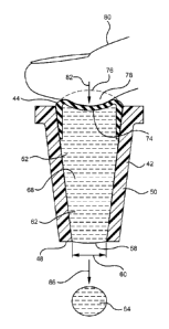
[0029] As illustrated in Figures 2 and 3, in additional to venting air 64 from
the
extravascular system 20, the vent plug 42 can collect a sample of blood 62
therein that can be
used for blood testing or other procedures. Figure 2 illustrates a close-up
view of the vent
plug 42 inserted into the opening 70 of a port 40 coupled to an extension tube
36, similar to
that of Figure 1, and Figure 3 illustrates a cross-sectional view of the
devices of Figure 2. As
illustrated, the vent plug 42 can include a body 50 that has a lumen 52
extending between the
proximal end 46 and the distal end 48 of the body 50. The body 50 can have a
variety of
shapes and sizes. As shown, the body 50 forms a tapered cylinder, but in other
embodiments,
the body 50 can have other shapes and sizes. In some embodiments, the membrane
44 is
disposed and/or coupled to the proximal lumen opening 72 of the body 50, as
shown, creating
a fluid chamber 68 within the lumen 52 and distal the membrane 44. The
membrane 44 can
have coupling portion 44b that is coupled to the body 50 of the vent plug 42.
The membrane
44 can have an exposed portion 44a that is biased to bulge proximally, as
shown. This
exposed portion 44a can bulge outwards a sufficient distance 54 that permits
the membrane
44 to be depressed by the average adult finger from the bulged position, or
pre-depressed
position (element 76 in Figure 4), to a depressed position (element 74 in
Figure 4), in order to
compress the volume of the fluid chamber sufficiently to expel a blood drop 84
therefrom, as
described below. In some embodiments, a blood drop is at least 0.05 mL.
Accordingly, in
some configurations, the membrane 44 is flexible, so that is can be depressed,
as shown in
Figure 4.
-6-
WO 2012/012400 CA 02808048 2013-01-17 PCT/US2011/044501
[0030] During venting, as blood 62 is forced into the vent plug 42, air 64
within the lumen
52 is forced through the membrane 44 via one or more air flow paths 56. During
this process,
a sample of blood 62 can be collected within the fluid chamber 68. The volume
of blood
collected can be controlled in part by the size of the fluid chamber 68, which
can thus be
designed to contain the desired volume of blood. Most blood tests require a
minimum of
about 0.1 L of blood, accordingly, the fluid chamber 68 can be at least this
big. In other
embodiments, the fluid chamber 68 is sized to contain up to about 10 mL of
blood. In other
embodiments, the fluid chamber 68 can be even larger than 10 mL.
[0031] In some embodiments, the vent plug 42 can be configured to retain blood
62 as it is
withdrawn from the port 40 to prevent blood spills and blood contamination.
Thus, in some
configurations, the distal lumen opening 58 is shaped and sized to retain
blood 62. Blood
retention within the lumen 52 is governed, at least in part, by the inner
perimeter of the distal
lumen opening 58, the surface tension of blood, and the force on the blood 62
to flow out of
the distal lumen opening 58. Accordingly, the inner perimeter of the distal
lumen opening 58
can be designed so that blood 62 is retained within the fluid chamber 68 when
the force of the
blood 62 to flow out of the distal lumen opening 58 is within a certain range,
but permit at
least some blood to flow out when the pressure on the blood 62 exceeds this
range.
[0032] For example, in some embodiments, when the distal lumen opening 58 is
circular,
an inner perimeter of less than or equal to approximately 2.0 mm, and a
diameter 60 of less
than or equal to approximately 0.6 mm, permits the retention of blood within
the lumen 52
against approximately the force of gravity. When the force on the blood 62 is
greater than the
force of gravity some blood 42 can flow out of the distal lumen opening 58.
Similarly, a
circular distal lumen opening 58 with a diameter of about 0.3 mm may retain
blood 62 therein
against forces stronger than gravity, such as bumping, jarring, and movement
of the filled
vent plug 42. When the distal lumen opening 58 has a very small inner
perimeter, the force
required to expel blood 62 will be very large.
[0033] As shown in Figures 4 and 5, in some embodiments, the vent plug 42 is
able to
expel blood 62 out of the vent plug 42 after it is withdrawn from a port 40.
Referring to
Figure 5 specifically, in some instances, blood 62 collected with the vent
plug 42 can be
expelled onto a test strip or onto another object for testing purposes when a
finger 80 presses
against the membrane 44 to increase the pressure within the lumen 52. This
process will be
described in greater detail below. To facilitate blood expulsion, the distal
lumen opening 58
can be configured large enough so that an average adult finger can apply
sufficient pressure
to expel a blood drop 84 from the fluid chamber 68. Thus, in some embodiments,
the distal
-7-
WO 2012/012400 CA 02808048 2013-01-17 PCT/US2011/044501
lumen opening 58 has a inner perimeter greater than or equal to about 0.3 mm,
which when
the distal lumen opening 58 is a circular opening, corresponds to a diameter
of about 0.1
mm. Thus, in some configurations, the distal lumen opening 58 has an inner
perimeter
between about 0.3 mm to about 2.0 mm. In some configurations, the distal lumen
opening 58
is approximately circular and has a diameter between about 0.1 mm to about 0.6
mm. In
other embodiments, the distal lumen opening 58 is non-circular.
[0034] Reference will now be made to Figure 4. Figure 4 illustrates a cross-
section view
of a vent plug 42 after it is removed from a port 40. Similar to the vent plug
42 illustrated in
Figure 3, a membrane 44 is coupled to a top portion of the body 50 of the vent
plug 42. In
some embodiments, the membrane 44 is coupled to an inner surface of the inner
lumen 52 of
the body. This coupling can be mechanical or chemical, for example, using an
adhesive or
another fastener 64. In other embodiments, the membrane 44 is coupled to a top
surface of
the body 50 rather than being disposed within the lumen 52.
[0035] In some configurations, the membrane 44 is biased to bulge proximally,
as shown
in Figure 3. The bulging portion can act as a button that when sufficiently
pressed downward
82 may cause one or more blood drops 84 to drop from the fluid chamber 68. As
shown in
Figure 4, the bulging nature of the membrane 44 positions the membrane 44 in a
pre-
depressed position 76 until it is depressed to a depressed position 74 by the
downward 82
force of a finger 80. This downward 82 force results in a decrease in the
volume of the fluid
chamber 68 that is approximately equal to the volume of displacement 78
between the pre-
depressed 76 and depressed 74 positions of the membrane 44, as shown. As the
volume of
the fluid chamber 68 decreases, the pressure within the fluid chamber 68
increases. In some
instances, this pressure increase within the fluid chamber 68 causes one or
more blood drops
84 to be expelled downward 82 and out of the fluid chamber 68, as shown. After
the blood
drop 84 is expelled and the pressure of the finger 80 is released, the
membrane 44 is
permitted to return to its biased pre-depressed position 76. As the membrane
44 moves
upward, the volume of the fluid chamber 68 expands decreasing the internal
pressure of the
fluid chamber 68, drawing air therein. This new air may move upwards as the
heavier blood
62 sinks toward the distal lumen opening 58. At this point, the membrane 44 of
the vent plug
42 can be depressed again to expel another blood drop 84. Thus, as described,
in some
embodiments, the vent plug 42 can be selectively activated to release blood
drops 84 on
command, as shown in Figures 4 and 5.
[0036] Figure 5 depicts the action of selectively releasing blood drops 84
from the vent
plug 42 onto a surface. As shown, a practitioner can grip the vent plug 42
with one or more
-8-
WO 2012/012400 CA 02808048 2013-01-17 PCT/US2011/044501
fingers 80. Then by sufficiently depressing the membrane 44, the practitioner
can expel one
or more blood drops 84 from the vent plug 42. In some embodiments, the volume
of
displacement 78 between the pre-depressed position 76 and the depressed
position 74 can be
designed to cause the expulsion of two or more blood drops 84 or a single
large blood drop
84. Furthermore, in some embodiments, the membrane 44 is configured so that it
is capable
of being only partially depressed so that a smaller blood drop 84 is expelled
than would be if
the membrane 44 were completely depressed.
[0037] As shown in Figure 5, in some embodiments, the body 50 of the vent plug
42 is
shaped and sizes so that it can be gripped between two or more fingers 80.
Accordingly, in
some configurations, the length 70 of the body 50 is approximately equal to or
greater than
the width of the average human thumb. The body 50 can also be wide enough to
be
adequately gripped within two or more fingers 80. As further shown, in some
embodiments,
the body 50 includes a top disk 92 or other like structure from which the
membrane 44 bulges
outward. This top disk 92 can be used to leverage the vent plug 42 out of a
port 40 and/or to
prevent a finger 80 that is gripping the side of the body 50 from accidentally
depressing the
membrane 44.
[0038] Figure 6 depicts a vent plug 42 having a membrane 102 disposed within
the lumen
52. In this position, the membrane 102 divides the lumen 52 into an air
chamber 114
proximal the membrane 102 and a fluid chamber 68 distal the membrane 102.
Similar to the
embodiments of Figures 4 and 5, the vent plug 42 of Figures 6 and 7 can be
capable of
expelling one or more drops of blood 84 when a finger 80 is pressed downward
82 against the
proximal lumen opening 72 of the body 50. However, different from the
embodiments of
Figures 4 and 5, the vent plug 42 of Figures 6 and 7 expels blood 62 as air is
forced from the
air chamber 114 through the membrane 102 into the fluid chamber 58 rather than
in response
to the movement of the membrane 102. This increase of air increases the
internal pressure
inside the fluid chamber, which can cause one or more drops of blood to be
expelled out the
distal lumen opening 58.
[0039] In some embodiments, to more effectively expel a blood drop 84, the
finger 80
covers the proximal lumen opening 72 to seal this opening. Once sealed, or
substantially
sealed, the finger 80 can be pressed deeper (distally) into the lumen 52 to
compress the air 64
within the air chamber 114. In some configurations, the proximal lumen opening
72 is
rounded, to provide more comfort to the practitioner and to facilitate sealing
of this opening.
Likewise, in other configurations, the proximal lumen opening 72 includes a
cushion, such as
-9-
WO 2012/012400 CA 02808048 2013-01-17 PCT/US2011/044501
an elastomeric material disposed thereon. In some embodiments, this cushion
can act as a
compressible member, as will be described below.
[0040] As shown in Figures 6 and 7, as a finger 80 is pressed downward 82
against the
proximal lumen opening 72, air 64 can enter the air chamber 114 via flow paths
108 between
the finger 80 and the body 50 of the vent plug 42. As the finger 80 presses
farther against the
inner surface 116 of the proximal lumen opening 72 it can at least partially
seal the proximal
lumen opening 72 and compressed the air 64 within the air chamber 114. The
distance 106
between the proximal lumen opening 72 and the membrane 102 can be far enough
that the
average adult finger 80 does not contact the membrane 102 as the finger 80 is
pressed against
the proximal lumen opening 72. The compression of air within the air chamber
114 can force
air 64 through the membrane 102 into the fluid chamber 68. As this air is
introduced into the
fluid chamber 68 it increases the pressure in that chamber and can cause one
or more blood
drops 84 to be expelled out the distal lumen opening 58. Accordingly, in some
embodiments,
the vent plug 42 can be selectively activated to release blood drops 84 on
command, similar
to the vent plug 42 depicted in Figure 5.
[0041] Figures 8 and 9 illustrate variations to the vent plug 42 shown in
Figures 6 and 7.
As shown, this vent plug 42 includes a compressible portion 122 that forms
part of the barrier
of the air chamber 114. This compressible portion 122 may include one or more
accordion-
type member 124 that compressed when a downward (distal) 82 force is applied
thereto.
Other types of compressible members can include a spring, an elastomer, or
another like
member. A compressible portion 122 can be made of the same material as the
remainder of
the body 50 or it can be made of a separate material, for example, as an
elastomeric material
like a rubber, silicone rubber, etc.
[0042] In some embodiments, the vent plug 42 is activated similarly to that of
Figures 6
and 7, as a finger 80 is pressed against the proximal lumen opening 72. The
finger 80 can
seal or substantially seal the air chamber 114 and compress the compressible
portion 122 of
the air chamber 114. The compressible portion 122 can enable additional
pressurization of the
air chamber 114, causing more air 64 to be forced through the membrane 102 as
it
compresses the height of the air chamber 114 from an uncompressed height 126
to a
compressed height 128. The decrease in height further pressurizes the air
chamber 114,
providing additional force for forcing air 64 through the membrane 102 and
expel one or
more blood drops 84 out the distal lumen opening 58, as described above.
[0043] From the foregoing, it will be seen that the embodiments of a vent plug
42
described herein can be used to vent an extravascular system 20 as well as
collecting a blood
-10-
WO 2012/012400 CA 02808048 2013-01-17 PCT/US2011/044501
sample and later and dispensing the blood sample. Thus, these embodiments of a
vent plug
42 reduce the number of steps and devices required to perform these
procedures, which can
decrease the time and cost of these procedures.
[0044] The present invention may be embodied in other specific forms without
departing
from its structures, methods, and/or other essential characteristics as
broadly described herein
and claimed hereinafter. The described embodiments are to be considered in all
respects only
as illustrative, and not restrictive. The scope of the invention is,
therefore, indicated by the
appended claims, rather than by the foregoing description. All changes that
come within the
meaning and range of equivalency of the claims are to be embraced within their
scope.
-11-