Note: Descriptions are shown in the official language in which they were submitted.
CA 02808387 2016-12-06
WO 2012/036707
PCl/US2010/052987
METHOD FOR AUTOMATED POSITION VERIFICATION
BACKGROUND
Cross-Reference to Related Application
100011 Deleted.
Field
100021 The disclosed and claimed concept relates generally to testing
equipment and
methodologies and, more particularly, to a method of automatically verifying a
position of a sensor during performance of an evaluation procedure on an
object
under test.
Related Art
100031 Periodic maintenance and evaluation are required for numerous types of
equipment. Certain types of equipment have very large numbers of components
that
are very similar to one another and the testing of which is likewise similar
to one
another, and thus it has been known to automate certain testing functions with
robots
and the like.
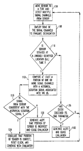
100041 In the evaluation of certain types of equipment, it is necessary to
evaluate a
degree of degradation or change over a period of time of the equipment. In
such
circumstances, it is typically necessary to compare the results of current
testing with
the results of prior testing. In so doing, it is necessary to retrieve
historical data,
compare it with current data, and evaluate any changes that have occurred in
order to
characterize the degradation of each such component of an object under test.
however, it is also necessary to ensure that the proper historical data is
being
compared with the proper current data. and it is therefore also necessary to
periodically verify that the position of the testing equipment is correct,
meaning that
the component which is being evaluated by sensors for comparison with
historical
data is the correct component and not, say, an adjacent, different component.
100051 It thus has been known to rely upon one or more Uniquely Identified
Locations (UILs) on an object under test to determine a current position of a
sensor,
for instance, of a testing apparatus. That is, the position of the sensor at
any given
time is determined in respect to one or more 1.111,s on the object under test.
It
CA 02808387 2013-02-14
WO 2012/036707
PCT/US2010/052987
therefore has also been known to periodically (during the course of an
evaluation
procedure) robotically move the sensor to one of the UILs in order to confirm
that the
position from which the sensor was moved to the UIL is, in fact, the position
where
the system believed it to be. While such methodologies have been generally
effective
for their intended purposes, they have not been without limitation.
[0006] An example of an environment in which an object under test has numerous
similar components that must be individually evaluated is in the case of a
steam
generator of a nuclear power plant. Such a steam generator might include ten
thousand or more tubes that are in fluid communication with a primary loop of
the
nuclear power plant, and each of the tubes must be periodically evaluated for
degradation in order to avoid the potential for leakage of primary coolant
into a
secondary loop. At various times, such testing is performed by causing a
robotically
controlled eddy current sensor to be passed through the various tubes of the
steam
generator, and the signal from the eddy current sensor is compared with a
historical
signal that is stored in a storage in order to enable an evaluation to be made
of
possible degradation of the tube. In order to ensure that the retrieved
historical data is
being compared with the proper current data, the robot moves the probe at
least once
every four hours, say, to a UIL to ensure that the position of the sensor
immediately
prior to its movement to the UIL was the position where the system believed
that the
sensor has been situated. However, such movement of the sensor to a UIL and
then
back to a component such as a tube has been time consuming and wasteful of
resources. It thus would be desired to provide an improved system that
overcomes
these and other shortcomings associated with the known art.
SUMMARY
[0007] An improved method for verifying a position of a sensor with respect to
an
object under test includes detecting a signal from the sensor that is
positioned at a
given location on an object under test and comparing the signal from the
sensor with a
historical signal that is associated with a Uniquely Identified Location (UIL)
on the
object under test. If the two signals are consistent, and if the position of
the sensor at
the given location on the object under test is the same as the UIL, it is
concluded that
the position of the sensor is correct and the evaluation procedure can
continue on the
object under test.
2
CA 02808387 2013-02-14
WO 2012/036707
PCT/US2010/052987
[0008] Accordingly, an aspect of the disclosed and claimed concept is to
provide an
improved method of verifying a position of a sensor with respect to an object
under
test by relying upon a signal from the sensor to assess the sensor's position
rather than
moving the sensor to a known location on the object under test to evaluate its
former
position.
[0009] Another aspect of the disclosed and claimed concept is to provide an
improved method of testing that saves time and avoids the wasting of valuable
resources.
[0010] Other aspects of the disclosed and claimed concept are provided by an
improved method of verifying a position of a sensor with respect to an object
under
test during an evaluation procedure performed with the use of the sensor on
the object
under test in which at least one of the sensor and the object under test moves
with
respect to the other of the sensor and the object under test. The general
nature of the
method can be stated as including detecting a signal from the sensor
positioned at a
location on the object under test, making a determination that the location on
the
object under test is the same as a Uniquely Identified Location (UIL) on the
object
under test, determining from a comparison of at least a portion of the signal
from the
sensor with at least a portion of a stored historical signal associated with
the UIL that
the signal from the sensor is consistent with the historical signal associated
with the
UIL and, responsive to the determining, concluding that the position of the
sensor
during the evaluation procedure is correct.
BRIEF DESCRIPTION OF THE DRAWINGS
[0011] A further understanding of the disclosed and claimed concept can be
gained
from the following Description when read in conjunction with the accompanying
drawings in which:
[0012] Fig. 1 is a schematic depiction of a facility that includes an object
under test
upon which an improved method in accordance with the disclosed and claimed
concept can be performed: and
[0013] Fig. 2 is a flowchart depicting certain aspects of the improved method.
[0014] Similar numerals refer to similar parts throughout the specification.
DESCRIPTION
[0015] An exemplary object under test 6 of an exemplary facility 10 is
depicted
generally in Fig. 1. While for purposes of the disclosure herein, the object
under test
3
CA 02808387 2013-02-14
WO 2012/036707
PCT/US2010/052987
6 is described as being a steam generator and the facility 10 is described as
being a
nuclear power plant, it is understood that other facilities and objects under
test can be
advantageously subjected to the improved method described herein without
departing
from the present concept. The exemplary facility 10 can be described as
further
comprising for a computer 14 that robotically controls an eddy current sensor
18 in
order to move the sensor 18 among and through the various tubes of the
exemplary
steam generator, i.e., the exemplary object under test 6. The computer 14
comprises a
processor and a storage, with one or more routines being stored in the storage
for
execution on the processor. The exemplary storage can be any one or more of
RAM,
ROM, EPROM, EEPROM, FLASH, and the like and in the depicted exemplary
embodiment includes a machine readable storage medium such as the exemplary CD-
ROM 22 depicted generally in Fig. 1
[0016] As is understood in the relevant art, a steam generator of a nuclear
power
plant includes a tube sheet that is in form of a plate of stainless steel or
other metal
that may be on the order of twenty-two inches thick. The two ends of each tube
pass
through the tube sheet and are affixed to the tube sheet by being
hydraulically
expanded into engagement with a hole formed in the tube sheet. The pattern of
expansion of the tube into engagement with the tube sheet is typically unique,
and the
patter of expansion as a function of distance along the tube can therefore be
stored in
the storage for subsequent retrieval. Depending upon a number of factors, such
as the
degree of uniqueness of the pattern of expansion of the tube within the tube
sheet, the
stored pattern of expansion can be relied upon as a Uniquely Identified
Location
(UIL) and, more particularly, as a UIL tube. That is, while any steam
generator may
include a number of locations such as plugged tubes, support rods, painted
tubes, and
the like that might serve as conventional UILs, in the present concept the
tubes
themselves are UILs and, more particularly, are UIL tubes based upon the
uniqueness
of the pattern of expansion of the tube metal into engagement with the tube
sheet.
[0017] That is, at the time of manufacture of the steam generator or at
another time,
the sensor 18 is passed through each tube and its signal is recorded and
stored in the
storage for future retrieval and comparison with another signal from the same
tube at
a later time. Such comparison is performed in order to assess the degradation
or other
change of the tube as a function of time. Advantageously, however, the
historical
signal stored in the storage can also be employed to designate the tube as a
UIL tube
4
CA 02808387 2013-02-14
WO 2012/036707 PCT/US2010/052987
if the pattern of expansion as represented by the historical signal is
sufficiently unique
from other historical signals of other nearby tubes. Each such historical
signal stored
in the storage will be associated with a particular tube of the steam
generator, and
more particularly, with the location of the tube on the steam generator. In
this regard,
it is noted that the expression "location" and variations thereof shall refer
generally to
the place where a portion of the object under test 6 is situated, whereas the
expression
"position" and variations thereof shall refer generally to the place where the
sensor 18
is situated.
[0018] During performance of an evaluation procedure on the steam generator,
the
eddy current sensor 18 is robotically manipulated by the computer 14 to pass
through
all of the tubes of the steam generator, which is the exemplary object under
test 6. It
is noted that the position of the sensor 18 may also be referred to as the
working point
of the robot. The eddy current sensor 18 typically has numerous data channels
which
enable output signals from the eddy current sensor 18 in different frequency
bands to
be simultaneously detected and recorded. Signals from some of the signal
channels of
the sensor 18 are usable for comparison with a retrieved historical signal for
the same
tube in order to evaluate the possible degradation of the tube. Signals from
other
signal channels of the sensor 18 are usable for comparison with certain
aspects of the
retrieved historical signal in order to verify the position of the sensor 18.
[0019] That is, the plurality of signal channels of the sensor 18 enable both
an
evaluation of possible degradation of the tube with certain of the channels as
well as
confirmation of the position of the sensor 18 with other channels. Each tube
is
evaluated for possible degradation. However, typically only those tubes which
are
designated as UIL tubes are additionally evaluated for purposes of verifying
the
position of the sensor 18. Any of a wide variety of criteria can be employed
in
establishing certain tubes as being UIL tubes. For example, a given tube might
have
one or more dents formed therein at specific locations along its length, and
such dents
likely will be sufficiently unique that they can serve as a signature of that
particular
tube. Similarly, one or more particular instances of wear of a tube and/or one
or more
instances of buffing of a tube may additionally or alternatively be employed
in
assessing a given tube as having a unique signal and therefore designating the
tube as
a UIL tube. However, in new installations, the tubes are likely to be largely
free of
dents, wear, and buffing, and thus the tubes that are designated as UIL tubes
typically
1
CA 02808387 2013-02-14
WO 2012/036707
PCT/US2010/052987
will be the tubes having the most unique pattern of expansion of the tube
against the
tube sheet. As can be readily understood, the historical location signal for
any given
UIL tube will be in the form a signal having an amplitude that varies as a
function of
distance into the tube.
[0020] The various locations of the UIL tubes on the steam generator are
compiled
in a list 26 that is stored in the storage and that is accessible to the
computer 14. Most
typically, when the computer 14 robotically moves the sensor 18 to a new tube
for
purposes of evaluating the tube, the location of the tube on the object under
test 6 is
compared with the list 26 to make a determination whether the location of the
tube is
the same as a UIL, meaning that the tube at the location is actually a UIL
tube. If the
tube is determined to not be a UIL tube, the sensor 18 is passed through the
length of
the tube and the signal from the sensor 18 is compared with a historical
degradation
signal that is stored in the storage and that is retrieved for purposes of
evaluating the
degradation of the tube.
[0021] On the other hand, if the location of the tube is identified in the
list 26 as
being the same as that of a UIL, meaning that the tube is a UIL tube, the
signal from
the sensor 18 is used both to evaluate degradation of the tube as well as to
confirm the
position of the sensor 18. That is, signal components from certain signal
channel of
the sensor 18 are compared with a historical degradation signal that has been
stored in
the storage and that is associated with the tube in order to evaluate
degradation, and
other signal components from other signal channels of the sensor 18 are
compared
with a historical location signal that is also stored in the storage. If the
location signal
components from the sensor 18 are determined to be consistent with the
historical
location signal that was retrieved from the storage, the position of the
sensor 18 is
verified and the evaluation procedure continues. That is, the position of the
sensor 18
is verified in the course of performing the evaluation operation on a tube and
without
resort to movement of the sensor 18 to and from a conventional UIL.
[0022] However, if a comparison of the location signal components from the
sensor
18 are inconsistent with the retrieved historical location signal, an alert is
generated in
order to indicate to a technician that the position of the sensor 18 is
suspect and is
likely incorrect. In such a situation, the evaluation procedure will be
suspended.
[00231 As has been suggested elsewhere herein, the requirements of the
facility 10
typically require that the position of the sensor 18 be verified periodically
and with a
6
CA 02808387 2013-02-14
WO 2012/036707
PCT/US2010/052987
certain level of frequency. For instance, the requirements of the facility 10
may be
that the position of the sensor must be verified every four hours at a
minimum. As
such, whenever the position of the sensor 18 is verified based upon a
comparison of a
location signal from the sensor 18 with a historical location signal from the
storage, a
"clock" is reset and the position of the sensor 18 will then need to be
verified again
within the next four hours (according to the example parameter set forth
herein). It is
understood that various other parameters may be required by the facility 10 to
be met
in order for the evaluation procedure to continue on the object under test 6.
[0024] A flowchart is depicted in Fig. 2 detailing certain aspects of an
improved
method of verifying a position of the sensor 18 with respect to the object
under test 6
in accordance with the disclosed and claimed concept. The method can be
generally
said to begin, as at 104, where the computer 14 robotically moves the sensor
18 to a
tube of a steam generator and multiple signal components from multiple signal
channels of the sensor 18 are detected. As has been set forth elsewhere
herein, the
exemplary facility 10 is a nuclear power plant and the exemplary object under
test 6 is
a steam generator of the nuclear power plant, but it is reiterated that the
method
described herein can be advantageously employed in other types of facilities
and other
objects under test without departing from the present concept. The signal
components
detected at 104 typically we be degradation signals, and such degradation
signals are
employed, as at 108, to evaluate degradation of the tube. Typically, a
historical
degradation signal that is associated with the tube is retrieved from the
storage, and a
comparison is performed between the retrieved historical degradation signal
and the
degradation signal received from the sensor 18.
[0025] It is also determined, as at 110, whether the location of the tube that
is being
evaluated by the sensor 18 is the same as that of a UIL tube. Such an inquiry
involves
comparing the location of the tube that is being evaluated (based upon the
position of
the sensor 18) with the list 26 of UILs. Such a determination can be performed
at any
time and is depicted in the flowchart of Fig. 2 as occurring subsequent to the
degradation evaluation at 108 merely for purposes of clarity, it being
understood that
the evaluation at 110 can be performed (and likely will be performed) prior to
the
detection of any signal from the sensor 18.
[0026] If it is determined as at 110 that the tube is a UIL tube, one or more
signal
channels of the sensor 18 that form a location signal are compared with a
retrieved
7
CA 02808387 2013-02-14
WO 2012/036707
PCT/US2010/052987
historical location signal that is associated with the UIL tube in order to
verify the
position of the sensor 18. If it is determined, as at 116, that the location
signal from
the sensor 18 is consistent with the historical location signal, processing
continues, as
at 124, where the system concludes that the position of the sensor 18 is
correct and is
therefore verified. In such a situation, the "clock" or other parameter of the
facility 10
is reset and the evaluation procedure continues. Processing thereafter
continues, as at
104.
[0027] However, if the location signal from the sensor 18 is determined, as at
116, to
be inconsistent with the retrieved historic location signal, processing
continues, as at
128, where an alert is generated to indicate that the position of the sensor
is suspect
and is likely incorrect. The evaluation procedure is then ceased.
[0028] As mentioned above, it is possible that the tube that is being
evaluated is not
a UIL tube, and in fact this is the more likely scenario in the present
exemplary
embodiment. That is, since in the exemplary embodiment the position of the
sensor
18 needs to be verified only once every four hours, and since the computer 14
can
evaluate approximately three hundred tubes per hour, roughly only one in about
twelve hundred tubes on average must be designated as a UIL tube. For reasons
of
simplicity, however, probably at least twice as many tubes will be designated
as UIL
tubes in order to avoid an unnecessary cessation of the evaluation procedure.
[0029] If it is determined, as at 110, that the tube is not a UIL tube, it is
still
determined, as at 136, whether the "clock" or other timing or other parameter
has
been exceeded, such as if more than four hours (by way of example) have
elapsed
since the last time the position of the sensor 18 was verified. If the timing
or other
parameters have not been exceeded, as at 136, processing continues, as at 104.
However, if the "clock" or other parameters have been exceed, as at 136,
processing
continues, as at 140, where an alert is generated and the evaluation procedure
is
ceased.
[0030] It thus can be seen from the foregoing that the position of the sensor
18 can
be verified by using signals, i.e., location signals from the sensor 18, that
are
generated and detected during the course of the evaluation procedure. The
designation of such UIL tubes thus avoids the need for the sensor 18 to be
periodically moved to a UIL such as a blocked tube, a support rod, or a
painted tube
in order to verify the position of the sensor 18, which results in saved time
and
8
CA 02808387 2013-02-14
WO 2012/036707
PCT/US2010/052987
reduced cost. Moreover, the automation of such position verification of the
sensor 18
avoids the need for a technician to independently evaluate visually, for
instance, the
position of the sensor 18 once it has been moved from a tube to a UIL such as
a
plugged tube, a support rod, or a painted rod, which spares expense and avoids
the
wasting of limited labor resources.
[0031] The present disclosure may be embodied in other specific forms without
departing from its spirit or essential characteristics. The described
embodiments are
to be considered in all respects only as illustrative and not restrictive. The
scope of
the disclosure is, therefore, indicated by the appended claims rather than by
the
foregoing description. All changes that come within the meaning and range of
equivalency of the claims are to be embraced within their scope.
9