Note: Descriptions are shown in the official language in which they were submitted.
CA 02808502 2013-02-15
WO 2012/037669 PCT/CA2011/050265
SYSTEM AND METHOD FOR DYNAMIC COORDINATION OF RADIO
RESOURCES USAGE IN A WIRELESS NETWORK ENVIRONMENT
CROSS-REFERENCE TO RELATED APPLICATION
This application claims the benefit of, and priority, to International
Application No.
PCT/CA2010/001463, filed September 23, 2010 under the title "SYSTEM AND METHOD
FOR DYNAMIC COORDINATION OF RADIO RESOURCES USAGE IN A WIRELESS
NETWORK ENVIRONMENT". The content of the above-noted patent application is
hereby expressly incorporated by reference into the detailed description
hereof.
FIELD OF THE DISCLOSURE
The present patent disclosure generally relates to mobile telecommunications
networks. More particularly, and not by way of any limitation, the present
patent disclosure
is directed to providing dynamic coordination of radio resource usage in a
network
environment.
BACKGROUND
In operation of mobile communications networks in spectra shared with other
systems an ongoing issue relates to assigning channels among the diverse
systems without
interference. In the shared or pooled spectrum, for example, lightly licensed
or "white
space" bands, there may be multiple networks, sources, and radio access
technologies
operating in the same geographic location as well as time-frequency spectra.
Further, some
channels may be unused by some systems or become available in local
geographical
locations at some times. Additionally, some channels may also be congested due
to traffic
or interference.
BRIEF DESCRIPTION OF THE DRAWINGS
A more complete understanding of the embodiments of the present patent
disclosure
may be had by reference to the following Detailed Description when taken in
conjunction
with the accompanying drawings wherein:
FIG. lA depicts an example radio network environment wherein radio resources
may
be managed in accordance with an embodiment of the present patent application;
FIG. 1B depicts an example radio network environment where channel occupancy
and location database (COLD) information may be deployed at one or more
elements of the
WO 2012/037669 CA 02808502 2013-02-15
PCT/CA2011/050265
network environment in a distributed architecture for purposes of the present
patent
application;
FIG. 2A depicts an example LTE-based radio network having interactivity with a
database of sensory data (e.g., channel occupancy and location information) in
accordance
with an embodiment of the present patent application;
FIG. 2B depicts a diagram of additional details pertaining to the example
network of
FIG. 2A in one aspect;
FIG. 2C depicts a diagram of a protocol architecture relative to the example
network
of FIG. 2A;
FIGS. 2D and 2E depict example frame structures operable with the network of
FIG.
2A;
FIG. 2F depicts an example resource grid where resource elements may be
allocated
relative to the example network of FIG. 2A according to an embodiment of the
present
disclosure;FIG. 3 depicts a block diagram of an example wireless UE device
according to one
embodiment of the present patent application;
FIG. 4 is an example radio network scenario where a sensing element (e.g., a
mobile
communications device (MCD) or UE device) may be configured to sense radio
resource
conditions in both licensed and unlicensed wavelengths according to an
embodiment of the
present patent application;
FIGS. 5A and 5B are flowcharts of embodiments of a radio resource management,
usage and allocation scheme of the present disclosure;
FIG. 6A is a diagrammatic representation of a sensory information acquisition
process according to one embodiment;
FIG. 6B is an example radio network scenario illustrative of a sensory
information
reporting process by proxy according to one embodiment of the present patent
application;
FIG. 7 is a diagrammatic representation of a sensory information acquisition
process
according to one embodiment wherein a network node (e.g., a base station) is
operative as a
sensing element;
FIG. 8 is a diagrammatic representation illustrative of a network node passing
requests for sensing to a UE device according to one embodiment of the present
patent
application;
FIG. 9 is a diagrammatic representation that illustrates exchange of commands
or
messages relative to radio resource allocation in one embodiment;2
WO 2012/037669 CA
02808502 2013-02-15
PCT/CA2011/050265
FIGS. 10A and 10B are a diagrammatic representation illustrative of exemplary
processes at an embodiment of a COLD server of the present patent application;
FIG. 11 is a diagrammatic representation illustrative of exemplary processes
with
respect to an embodiment of a distributed COLD architecture of the present
patent
application;
FIG. 12 is an arrangement illustrative of an example radio network scenario
where
multiple sensing elements (e.g.. UE devices and network nodes) interoperate in
a distributed
COLD environment; and
FIG. 13 is an arrangement illustrative of an example radio environment with
multi-
system mobile networks that may interoperate for purposes of radio resources
management
according to an embodiment of the present patent application.
DETAILED DESCRIPTION OF THE DRAWINGS
The present patent disclosure is broadly directed to providing dynamic
coordination
of resource usage in a diverse radio network environment. Various network
elements,
user equipment (UE) devices, base stations, and other nodes are configured to
operate as a
sensor network across one or more radio access technologies (RATs) to improve
the
efficiency and capacity of a mobile communications network.
In one aspect, an embodiment of a radio resource management method utilizing
multiple RATs in a communications network is disclosed. The claimed embodiment
comprises the following acts: scanning, by a sensing element, multiple radio
frequency
spectra for detecting sensory data associated with multiple radio channels
relative to a first
radio element; communicating the sensory data to a network node; and based on
the detected
sensory data, allocating a radio resource to a second radio element.
In another aspect, an embodiment of a radio resource management system or
apparatus is disclosed. The claimed embodiment comprises: a component
configured to
receive sensory data from one or more sensing elements operating in multiple
RATs and
multiple radio frequency spectra; a component configured to process the
sensory data
received from the one or more sensing elements; and a component configured to
send a
control message, based on the processing, for effectuating allocation of a
radio resource to at
least one radio element operating in a radio network environment.
In a further aspect, an embodiment of a wireless user equipment (UE) device is
disclosed, wherein the claimed embodiment comprises: a processor configured to
control at
least one of a plurality of subsystems to scan multiple radio frequency
spectra for detecting3
WO 2012/037669 CA 02808502 2013-02-15 PCT/CA2011/050265
sensory data associated with multiple radio channels relative to one or more
radio elements;
the processor further configured to control at least one of the plurality of
subsystems to
generate a message for reporting at least a portion of the sensory data to at
least network
node; and the processor further configured to control at least one of the
plurality of
subsystems to process a control message received from one of the network nodes
for
facilitating allocation of a radio resource to the wireless UE device.
In a further aspect, disclosed herein is an embodiment of method of processing
sensory reports of one or more sensing elements in a distributed channel
occupancy and
location database (COLD) system. The claimed embodiment comprises one or more
of the
following acts: receiving a sensory report from a sensing element operating in
multiple
RATs, the sensory report including sensory data associated with multiple radio
channels
relative to at least one radio element; identifying the sensing element's
identity and
determining if the sensory report has been tagged with a code generated by a
predetermined
code generator; responsive to the identifying and the determining,
authenticating the sensory
report; and correlating the sensory report from the sensing element with at
least one of one
or more previous sensory reports from the sensing element and one or more
previous
sensory reports received from another sensing element.
In a related aspect, disclosed herein is an embodiment of an apparatus for
processing
sensory reports of one or more sensing elements in a distributed COLD system.
The
claimed embodiment comprises one or more of the following features: a
component
configured to receive a sensory report from a sensing element operating in
multiple RATs,
the sensory report including sensory data associated with multiple radio
channels relative to
at least one radio element; a component configured to identify the sensing
element's identity
and to determine if the sensory report has been tagged with a code generated
by a
predetermined code generator; a component configured to authenticate the
sensory report;
and a component configured to correlate the sensory report from the sensing
element with at
least one of one or more previous sensory reports from the sensing element and
one or more
previous sensory reports received from another sensing element.
In a still further aspect, disclosed herein is an embodiment of a method
operable with
a wireless UE device in a radio communications environment utilizing multiple
radio access
technologies. The claimed embodiment comprises one or more of the following
acts:
scanning multiple radio frequency spectra for detecting sensory data
associated with
multiple radio channels relative to at least one radio element in a sensing
area of the wireless
UE device; determining if the wireless UE device is out of range of a wide
area cellular
CA 02808502 2013-02-15
WO 2012/037669 PCT/CA2011/050265
network; responsive to the determining, establishing a short-range wireless
communication
path with another wireless UE device having a wide area cellular communication
connection; and transmitting the sensory data to the another wireless UE
device for reporting
to a network element associated with the wide area cellular network.
In a related aspect, disclosed herein is another embodiment of a wireless UE
device
that comprises one or more of the following features: a processor configured
to control at
least one of a plurality of subsystems to scan multiple radio frequency
spectra for detecting
sensory data associated with multiple radio channels relative to at least one
radio element
utilizing multiple radio access technologies in a sensing area of the wireless
UE device; the
processor further configured to control at least one of the plurality of
subsystems to
determine if the wireless UE device is out of range of a wide area cellular
network; the
processor further configured to control at least one of the plurality of
subsystems to establish
a short-range wireless communication path with another wireless UE device
having a wide
area cellular communication connection; and the processor further configured
to control at
least one of the plurality of subsystems to transmit the sensory data to the
another wireless
UE device for reporting to a network element associated with the wide area
cellular network.
Embodiments of systems, methods, apparatuses and associated tangible computer-
readable media having instructions and tangible computer program products
relating to
dynamic coordination of radio resources usage and allocation in a radio
network of the
present patent disclosure will now be described with reference to various
examples of how
the embodiments can be made and used. Like reference numerals are used
throughout the
description and several views of the drawings to indicate like or
corresponding parts to the
extent feasible, wherein the various elements may not necessarily be drawn to
scale.
Referring now to the drawings, and more particularly to FIG. 1A, depicted
therein is an
example radio network environment 100A wherein radio resources may be managed
in
accordance with an embodiment of the present patent application. It should be
recognized
that the radio network environment 100A may be comprised of one or more
diverse
networks deployed by respective operators using any known or heretofore
unknown
technologies involving radio communications, for example, including but not
limited to wide
area cellular networks. WiFi networks, Wi-MAX networks, television (TV)
broadcast
networks, satellite communications networks, and the like. Further, radio
frequencies
utilized in the diverse technologies may comprise different licensed spectral
bands,
unlicensed spectral bands, shared or pooled radio frequencies, other lightly
licensed bands,
fixed TV white space bands (e.g., unused television frequencies between 54-698
MHz), and
5
CA 02808502 2013-02-15
WO 2012/037669 PCT/CA2011/050265
so on. Furthermore, the radio frequencies operable within the radio network
environment
100A may be compatible with Global System for Mobile Communications (GSM)
networks,
Enhanced Data Rates for GSM Evolution (EDGE) networks, Integrated Digital
Enhanced
Networks (IDEN), Code Division Multiple Access (CDMA) networks, Universal
Mobile
Telecommunications System (UMTS) networks, any 2nd- 2.5- 3rd- or subsequent
Generation networks, Long Term Evolution (LTE) networks (i.e., Enhanced UMTS
Terrestrial Radio Access or E-UTRA networks), networks capable of High Speed
Downlink
Packet Access (HSDPA) or High Speed Uplink Packet Access (HSUPA), or wireless
networks employing standards such as Institute of Electrical and Electronics
Engineers
(IEEE) standards, like IEEE 802.11a/b/g/n standards or other related standards
such as
HiperLan standard, HiperLan II standard, Wi-MAX standard, OpenAir standard,
and
Bluetooth standard, as well as any mobile satellite communications technology
such as Geo
Mobile Radio (GMR)-1, and other satellite-based technologies, e.g., GPS.
Accordingly, the
radio network environment 100A illustrated in FIG. 1A is envisaged to be a
comprehensive
environment that can also include other elements such as femto cells and pico
cells (that
extend coverage to indoor areas, for example), WiFi access points, relay
nodes, and the like.
By way of illustration, various coverage areas of the radio network
environment
100A are exemplified with one or more network infrastructure elements such as
base
stations that may be interconnected as well as connected to other network
components such
as radio network controllers (RNCs), core networks, and other network nodes.
Reference
numerals 102-1 through 102-5 refer to five example coverage areas each being
served by a
corresponding base station 104-1 through 104-5. Although the coverage areas
102-1 to 102-
5 are shown as distinctly separate areas, they may be overlapped. Also,
whereas only one
base station is illustrated with respect to a coverage area, there may be
additional base
stations overlapping the same coverage area that operate in the same or
different radio access
technologies (RATs). Again by example, base station 104-1 serving the coverage
area 102-1
is operable with a suitable radio access technology, e.g., RAT-B. Likewise,
base station
104-2 may also operate with RAT-B, whereas base stations 104-3 through 104-5
may
operate with RAT-A, RAT-D and RAT-C, respectively. Depending on the radio
access
technology, a base station may be coupled to an RNC 106 for connecting with an
associated
core network 108. Where an LTE-based network implementation is involved, the
base
station functionality as well as the RNC functionality may be integrated in a
single radio
network element known as evolved Node B (eNB). Additionally, a base station
may be
provided with peer-to-peer connectivity (e.g., a backhaul link) with other
base stations,
6
CA 02808502 2013-02-15
WO 2012/037669 PCT/CA2011/050265
which may be employed in one embodiment for exchanging sensory data
information as
well as resource allocation and management/usage messages, as will be
described below.
Each coverage area may serve a number of mobile communications devices (which
may also be somewhat interchangeably referred to as wireless user equipment
(UE) devices,
wireless terminals, mobile terminals, mobile stations, white-space devices,
etcetera). In a
more general representation, a wireless UE device may also comprise any
portable computer
(e.g., laptops, palmtops, or handheld computing devices) capable of wireless
communication
or any enhanced personal digital assistant (PDA) device or integrated
information appliance
capable of email, video mail, Internet access, corporate data access,
messaging, calendaring
and scheduling, information management, and the like, that may be operable in
one or more
modes of operation. For example, a UE device may operate in the cellular
telephony band
frequencies as well as wireless Local Area Network (WLAN) bands, or possibly
in the
WLAN bands alone. Further, other bands in which the UE device could operate
wirelessly
may comprise Wi-MAX bands, one or more satellite bands, TV white space bands,
etc. As
illustrated with respect to the coverage areas of the radio network
environment 100A,
reference numerals 110-1 through 110-4 refer to the example wireless UE
devices that may
operate in different coverage areas. Further, some of the UE devices may be
provided with
the capability to engage in inter-device communications whereby two devices
(e.g., MCD
110-3A and MCD 110-3B in coverage area 102-3) may exchange information in peer-
to-
peer radio links. In some instances, one or more UE devices may communicate
using a
satellite-based system (e.g., communications satellite 111). As will be
described in
additional detail below, one or more UE devices may also be configured in an
embodiment
to operate as a sensing element for detecting various pieces of sensory data
in one or more
radio channels of the radio network environment 100A.
Network 108 is illustrative of one or more core networks with which the
various
corresponding radio access networks (including, e.g., the base stations and
eNB nodes, etc.)
communicate for effectuating communication processes as well as for providing
interactivity
with other network domains. For instance, one or more mobile switching centers
(MSCs),
short message service centers (SMSCs), home location/visited location
registers, (e.g.,
HLR/VLR 118), authentication centers (e.g., Authentication, Authorization and
Accounting
(AAA) node 120), and the like may interoperate as part of or in conjunction
with the
network 108. In some embodiments, although not specifically shown in FIG. 1A,
an IP
Multimedia Subsystem (IMS) network and associated functional entities (e.g.,
Call Session
Control Function (CSCF) nodes, network domain selection (NeDS) nodes, and
other
7
CA 02808502 2013-02-15
WO 2012/037669 PCT/CA2011/050265
application servers) may also be interfaced with the network 108. With respect
to
connectivity to public switched and IP service networks (e.g., the Internet)
114, appropriate
gateway nodes (e.g., a Gateway GPRS Support Node or GGSN 116) may also be
provided
in association with the network 108. Likewise, satellite-based radio
communications
infrastructure (e.g., satellite ground stations 112 that support and control
uplink and
downlink communications with communications satellites 111) may also be
suitably
interfaced with the service network 114.
In accordance with the teachings of the present patent application, various
elements
of the radio network environment 100A may be used as sensing elements to
monitor,
determine, detect or otherwise measure radio resource usage and interference
conditions at
one or more geographic locations within a coverage area of region of a
network. Each
element of the network may act as a radio condition "sensor- (i.e., a sensing
element), which
can include existing network elements with sensing capability (e.g., base
stations) or
standalone sensing elements/modules coupled to the existing network elements.
Sensing
elements may comprise base stations, mobile/nomadic devices, relays, femto
cells, pico cells
and other access points in an area of interest and may operate across single
or multiple radio
access technologies as an overlay sensor network to sense radio conditions in
the
environment in order to help improve the efficiency and capacity of a mobile
communications network. Accordingly, the sensors are configured to measure and
report
radio resource usage and interference conditions (i.e., sensory data) at
various geographical
locations and spectrum bands within a coverage area of a network. In one
embodiment, the
sensory data information may be reported to and consolidated at a channel
occupancy and
location database (COLD) 122 as shown in FIG. 1A, that can be updated
dynamically to
provide the elements of the network with a real-time view of the channel usage
throughout
the network. The COLD database 122 may therefore be suitably interfaced with
the network
infrastructure (e.g., via appropriate connections to the core network 108. RAN
elements such
as base stations or eNBs, etc.). Additionally, the COLD database 122 may be
coupled to the
service network 114 for exchanging radio conditions information with other,
possibly third-
party, external channel occupancy databases, e.g.. ECOD 124, among others.
In another embodiment, the radio conditions information (i.e., sensory data)
may
alternatively or additionally be stored in distributed COLDs at nodes
throughout a radio
network including, e.g., mobile devices, but not limited thereto. The
distributed COLDs
share and exchange information in order to disseminate sensing information
throughout the
CA 02808502 2013-02-15
WO 2012/037669 PCT/CA2011/050265
network. This configuration may be used to manage mobile communications
traffic in the
network or for device-to-device communications. One of ordinary skill will
recognize that
sensor network information may also be used to improve the overall efficiency
of the
network and its sensors. FIG. 1B depicts an example radio network environment
100B
where COLD information may be deployed at one or more elements of the network
environment in a distributed architecture for purposes of the present patent
application. It
should be appreciated that the radio network environment 100B of FIG. 1B is
essentially
similar to the radio network environment 100A illustrated in FIG. lA in its
representation of
the exemplary and comprehensive scope of a radio network environment.
Accordingly, the
description of FIG. 1A is equally applicable here, mutatis mutandis. However,
in
accordance with the alternative embodiment of the distributed COLD
architecture, the radio
network environment 100B includes one or more mobile devices having a COLD
database
and appropriate sensor/processor logic for effectuating the sensing, reporting
and processing
of the sensed COLD information in their respective micro radio environments
(i.e., a small,
localized area, hereinafter referred to as "sensing area", within which a UE
device's radio
transceiver circuitry can effectively sense the channel conditions prevalent
in that area,
which is much smaller than a coverage area of a base station due to the UE
device's lower
operating power conditions). Additionally, a network-located filtering and
COLD server
functionality 160 may be provided within or in association with the core
network
infrastructure 108 also. By way of illustration, UE device 110-3C in the
coverage area 102-
3 of base station 104-3 in FIG. 1B is provided with a local COLD
processor/logic element
162. In similar fashion, UE device 110-4 in the coverage area 102-5 and UE
device 110-2 in
the coverage area of 102-2 are also provided with respective local COLD
processor/logic
functionalities 164, 168, for sensing, reporting, and processing the sensed
local radio
conditions. In addition, depending on the enhanced functionalities of a UE
device having
the COLD processor/logic, the sensing UE device may be configured to manage
its own
radio resource usage, or schedule a radio resource to another radio element in
its vicinity
(e.g., another UE device), or generate appropriate messages to a network node
adapted to
schedule radio resources within a coverage area.
Regardless of where the sensory data is stored or warehoused, the COLD
information
may be dynamically updated from input messages received from each sensor of
the sensor
network with its specific location and usage parameters such as, e.g.,
interference levels and
time of observation. As mentioned previously herein, such dynamically-updated
information
9
CA 02808502 2013-02-15
WO 2012/037669 PCT/CA2011/050265
may be combined with channel occupancy information from other external channel
occupancy databases (ECODs) that may indicate relatively static channel
availability in the
spectral bands such as TV white spaces and other lightly licensed or pooled
spectral
resources. In a distributed architecture, there may be multiple COLD
facilities and in some
implementations the COLD may be a distributed function among multiple nodes in
the
network including, or possibly exclusively, the mobile terminals in one
specific
implementation. The storage of sensory information in the database, and
functioning of the
COLD server to provide location/channel occupancy information is suited to,
but not limited
to, applications of shared or pooled spectrum in which multiple systems may
utilize the same
spectrum assignments involving both licensed and unlicensed spectrum channels.
In cases
where the spectrum is shared or pooled, there can be multiple interference
sources. RATs,
and networks operating in the same area and utilizing common radio spectrum
resources.
Accordingly, the dynamically-updated sensory data (e.g., the interference
levels, signal to
interference ratios (SIRs), signal to noise ratio (SNR) levels, inter-symbol
interference (1ST)
delays and associated location information) is useful in such scenarios for
facilitating and
effectuating a more intelligent resource scheduling by schedulers that can be
device-located,
network-located, or both. Further, the sensory data information may also be
useful to the
management of device-to-device session coordination as mentioned previously
herein, since
such communication may not follow the cellular frequency reuse pattern that is
prevalent in
radio communications networks. If significant inference is reported in a
geographical area
on a specific channel, the mobile network can identify and assign other
channels that have
less interference, or choose to schedule the session in another manner.
In addition, the COLD information can also be used manage and improve
efficiency
of the sensor network itself. For example, if multiple devices are located
very near each
other, the COLD sever can choose to request information from a subset or only
one of the
devices to limit battery use and signaling. As a result, those devices near
other sensing
elements such as base stations may not be requested to provide sensory
information. In
some implementations where devices are configured to provide sensory
information, the
COLD server functionality can specifically signal certain mobile devices to
not provide
sensory information, or to provide less (or more) information, or to provide
decreased (or
increased) frequency of the reporting of information in order to better manage
the sensory
device resources.
In some embodiments, the COLD functionality may make use of information about
WO 2012/037669 CA 02808502 2013-02-15 PCT/CA2011/050265
channel activities in addition to that provided directly by sensing elements.
For example,
many of the RATs include in their operations and protocols feedback
information that
communicates the state of the radio channel (e.g., channel state information
feedback and
channel sounding measures). This information is generally directly used by the
radio
apparatus to adapt the modulation and coding scheme (MCS) to the current
channel
condition. In accordance herewith, some sensory elements (such as base
stations and mobile
devices) may extract the channel condition information from these processes
and make it
available to the COLD server(s), possibly together with other aspects such as
location,
time-of-day information, reliability/confidence levels and the granularity of
data. For
example, local information available to local COLD servers may include details
of dynamic
channel occupancy such as type of signal, users/devices, and duration and
manner of usage
(which are illustrative of finer granularity), while high level COLD servers
may contain
"coarse" information such as whether a channel is active and the loading on
that channel
(which are illustrative of coarse granularity). It should be appreciated that
making such
information available through the COLD can improve the overall network channel
utilization through better scheduling arrangements.
Using the radio network environments of FIGS. 1A and 1B as an example, UE
device 110-3C may be configured to report its location and sensory information
about
activity and interference on channels as may be requested by the COLD server
(e.g., COLD
server 122 of FIG. 1A or any network-located server in a distributed
environment of FIG.
1B). For instance, the device may be configured to report sensory information
autonomously, on request, or periodically or in the event of change (i.e.,
event-driven or
event-triggered) or of a radio condition (e.g., changing a spectrum etc.). In
general, each
device or element of the network senses the channel directly related to it and
reports to the
base station, a COLD server, or both. Accordingly, UE device 110-3C may sense
interference and channel usage from nearby communication between UE device 110-
3A and
UE device 110-3B, and the base station or node (e.g., base station 104-3), as
well as the
signaling from the base station 104-3 to those devices. That is, UE device 110-
3C is
configured to monitor both the uplink channels (from the devices to the
network nodes) as
well as the downlink channels (from the network nodes to the devices).
Further, UE device
110-3C may also sense the device-to-device communications between UE device
110-3A
and UE device 110-3B, as well as transmissions from transmitters (and/or other
mobile
devices) in base station coverage areas 102-1 and 102-4 because of their
proximity to or
WO 2012/037669 CA 02808502 2013-02-15 PCT/CA2011/050265
overlap with the sensory coverage of UE device 110-3C. Likewise, UE device 110-
3C may
also be provided with the capability to sense and report information on
channel usage by UE
device 110-4 and base station 104-5 which may belong to another network or a
different
radio access technology. In some implementations, base stations from several
networks may
be "consolidated" so that a sensing UE device may be able to sense
transmitters from several
networks/technologies using a communications channel in a given area. Using
the
information of location and interference feedback by UE device 110-3C and
other sensing
elements of the overlay sensor network, the COLD severer(s) can provide
information as to
scheduling communications on various channels and managing the device-to-
device
communications.
Based on the foregoing, it should be appreciated that the sensory data (e.g.,
channel
occupancy/location data) may be stored and processed with respect to various
parameters of
activity of different channels at different locations. Such information,
gathered through
sensory reports from sensory elements in a sensor network, may be processed
with other
reports of sensory information, and may be stored in one or more databases,
centralized,
distributed, or a combination thereof. Such information can be used for radio
resource
management (RRM) by providing knowledge of channel use and availability, as
well as
more detailed parameters regarding the use of the channel at a given location.
Accordingly,
the radio resource allocation for devices using one or more mobile
communications
networks can be benefited by implementing a system as described herein that
includes one
or more of the following, inter alia: (i) sensing at the device the activity
of radio resources;
(ii) storing the sensory information in a database local to the device; (iii)
reporting the
sensory information to other devices; (iv) receiving sensory and database
information from
other devices or nodes in the communications network; and (v) processing the
information in
the database, together with received information to select and assign radio
resources for the
device for communications.
The foregoing teachings and certain aspects relating thereto may be further
exemplified within a particular type of network, e.g., an LTE-based network,
as set forth
immediately below. FIG. 2A depicts an example LTE-based radio network 200A
having
interactivity with a database 214 of sensory data (e.g., channel occupancy and
location
information) in accordance with an embodiment of the present patent
application. An LTE-
compliant UE device 202 is illustrative of one or more mobile devices provided
with a
sensor processing logic module 204 that facilitates sensory information
gathering, reporting
12
WO 2012/037669 CA
02808502 2013-02-15
PCT/CA2011/050265
and processing with respect to one or more RATs and radio frequency spectra
according to
one embodiment of the present patent application. An Evolved UTRAN 206 having
one or
more eNB nodes (of which eNB 208 is an illustrative representation) is
operable to serve the
UE device 202 with respect to the air interface and RNC functionality. At a
higher
hierarchical network level is an Evolved Packet Core (EPC) network 210 coupled
to E-
UTRAN 206, which comprises network entities relating to mobility management,
packet
data network interfacing as well as interfacing to the E-UTRAN. These
functionalities are
represented by entities such as a Mobility Management Entity (MME) (which
manages
mobility. UE identity, and security parameters), a Serving Gateway (S-GW) (a
node that
terminates the interface towards the RAN), and a Packet Data Network (PDN)
Gateway (P-
GW) (a node that terminates the interface towards the PDN), collectively
illustrated as block
212 in the packet core 210. As illustrated, a sensory database 214 may be
disposed in a
communication relationship with the elements in E-UTRAN 206, packet core 210,
or both.
Additionally, the sensory database 214 may also be provided with the
capability to engage in
a communication relationship with UE device 202.
FIG. 2B depicts a portion 200B relating to the example network of FIG. 2A in
one
aspect wherein additional details are illustrated. The exemplary eNB node 208
includes
appropriate hardware/software/firmware functionality including, e.g., one or
more
processors, memory, radio transceiver circuitry, etc. to process the necessary
Layer-1 to
Layer-3 functions relative to a suitable communications protocol stack that
may be
effectuated with the UE device on one side and with the EPC elements on the
other side.
Reference numeral 216 refers to the physical layer (PHY) functionality,
reference numeral
218 refers to the Media Access Control (MAC) layer functionality, and
reference numeral
220 refers to a Radio Link Control (RLC) layer functionality. A Packet Data
Convergence
Protocol (PDCP) functionality 222 and a Radio Resource Control (RRC)
functionality 224
overlay the lower levels of the communication protocol architecture. Also
included in eNB
208 are a dynamic resource allocation (i.e., scheduling) module 226, a
measurement,
configuration and provision module 228, a radio admission control module 230,
a
connection mobility control module 232, a radio bearer (RB) control module 234
as well as
an inter-cell radio resource management (RRM) module 234 for effectuating the
necessary
radio interface functions.
Representative EPC network element 212 of the network portion 200B is coupled
to
eNB node 208 via Si interface 237. As illustrated in FIG. 2B, the network
element 212
includes MME functionality 242. S-GW functionality 238 as well as P-GW
functionality13
CA 02808502 2013-02-15
WO 2012/037669 PCT/CA2011/050265
240 that interfaces with an IP network, e.g., the Internet 114. At least part
of the
hardware/software/firmware functionality of eNB node 208 may be enhanced or
otherwise
modified to effectuate COLD server processes as well as sensory data
processes. For
example, sensing channel conditions associated with the eNB node's own radio
frequencies
as well as the other networks and technologies, generating sensory data
requests to other
sensing elements (UE devices, other base stations or eNB nodes (via an X2
interface, for
example), relay nodes, femto cells, pico cells, WiFi access points, etc.),
receiving and
processing sensory data inputs from other sensing elements, interfacing with
the sensory
database 214 for sending reports thereto, and the like, may be effectuated
based on the
implementation and service requirements. In one embodiment, such sensor
processing logic
and COLD server functionality may be represented as a functional block 225
provided as
part of eNB node 208, which may be configured to send appropriate sensory data
messages
or processed sensory data messages to the scheduler 226 in order to control or
otherwise
adjust resource allocation processes after taking into account prevalent
channel conditions,
occupancy and usage. Where the sensory data is processed elsewhere in the
network (e.g., at
the COLD server 214, at the EPC node 212 or at some other network element on a
different
hierarchical level) and is received at eNB 208 via suitable messaging, such
messaging may
be relayed to the scheduler functionality 226 for resource allocation
adjustment. Further, at
least part of the EPC node 212 hardware/software/firmware functionality may
also be
modified or otherwise configured to effectuate suitable sensor data processing
logic and
interfacing, which may be provided as a separate module 241 in some
embodiments,
whereby appropriate processes such as COLD server processes, generating
sensory data
requests to sensing elements, receiving and processing sensory data inputs
from sensing
elements, interfacing with the sensory database 214 for sending/receiving
reports, and the
like may be undertaken.
Both downlink and uplink communications in the LTE network portion 200B may
take place in a number of well defined channels that operate at different
levels of the
protocol stack that may be mapped from one level to the next. As will be set
forth below,
some of these channels may be suitably modified to carry the sensory data
information for
purposes of the present patent disclosure. FIG. 2C depicts a diagram of a
protocol
architecture 200C relative to the example network of FIG. 2A from the
perspective of the
communication channels. A number of physical channels carry information
between the
radio apparatus 250 and PHY layer 252 that forms Layer-1 251 of the protocol
architecture.
With respect to downlink communications, the physical channels comprise: (i)
Physical
14
CA 02808502 2013-02-15
WO 2012/037669 PCT/CA2011/050265
Broadcast Channel (PBCH); (ii) Physical Control Format Indicator Channel
(PCFICH); (iii)
Physical Downlink Control Channel (PDCCH); (iv) Physical Hybrid ARQ Indicator
Channel (PHICH); (v) Physical Downlink Shared Channel (PDSCH); and (vi)
Physical
Multicast Channel (PMCH). With respect to uplink communications, the physical
channels
comprise: (i) Physical Uplink Control Channel (PUCCH); (ii) Physical Uplink
Shared
Channel (PUSCH); and (iii) Physical Random Access Channel (PRACH). A plurality
of
Physical layer transport channels support information transfer from PHY layer
252 to MAC
and higher layers 254. For downlink communications, these channels are: (i)
Broadcast
Channel (BCH); (ii) Downlink Shared Channel (DL-SCH); (iii) Paging Channel
(PCH); and
(iv) Multicast Channel (MCH). For uplink communications, the transport
channels are: (i)
Uplink Shared Channel (UL-SCH) and (ii) Random Access Channel (RACH). In turn,
MAC layer 254 offers a plurality of logical channels to an RLC layer 256,
which comprise
control channels (control-plane information) and traffic channels (user-plane
information)
for uplink and downlink communications. These control channels comprise: (i)
Broadcast
Control Channel (BCCH); (ii) Paging Control Channel (PCCH); (iii) Common
Control
Channel (CCCH); (iv) Multicast Control Channel (MCCH); (v) Dedicated Control
Channel
(DCCH). The traffic channels comprise: (i) Dedicated Traffic Channel (DTCH)
and (ii)
Multicast Traffic Channel (MTCH). Both MAC layer 252 and RLC layer 256 form
Layer-2
253 functionality of the protocol architecture. At Layer-3 255 is RRC layer
258 that may
also communicate with PHY layer 252 for control and measurements relating to
the physical
channels.
Information may be transmitted in the LTE network portion 200B in two types of
radio frame structures: (i) Frequency Division Duplex (FDD) frame structure
(also referred
to as type 1 structure) and (ii) Time Division Duplex (TDD) frame structure
(also referred to
as type 2 structure), which define the time-frequency radio resources, i.e.,
the bandwidth of
the carrier (which is divided into several sub-bands or subcarriers) and the
time domain
(which is divided into time slots) into appropriate radio frames. Typically, a
radio frame has
a duration of 10 ms, wherein a resource block (RB) spans 12 subcarriers over a
slot duration
of 0.5 ms. The subcarrier spacing is 15 kHz, thereby giving a bandwidth of 180
kHz per
RB. FIGS. 2D and 2E depict example FDD and TDD frame structures 200D and 200E,
respectively, operable with the network of FIG. 2A. Each radio frame of 10 ms
is comprised
of 20 time slots of 0.5 ms, numbered from 0 to 19. For FDD operation, 10
subframes are
available for downlink transmission and 10 subframes are available for uplink
transmissions
in each 10 ms interval. With respect to a TDD frame, special subframes such as
Downlink
15
WO 2012/037669 CA 02808502 2013-02-15 PCT/CA2011/050265
Pilot Timeslot (DwPTS), Guard Period (GP) and Uplink Pilot Timeslot (UpPTS),
each
having configurable lengths may be interposed in between the subframes
carrying
information.
The transmitted signal in each slot may be described by a resource grid of
subcarriers
and symbols as illustrated in FIG. 2F wherein reference numeral 200F is a
graphical
representation of an array of time-frequency resources. Each element in the
resource grid is
called a resource element (RE) and is uniquely defined by an index pair (k,l)
in a slot (where
k and I are the indices in the frequency and time domain, respectively). An
exemplary radio
frame 260 is divided into 20 time slots, with each time slot (e.g., time slot
262) comprising 7
symbols. The smallest time-frequency unit for transmission, i.e., a resource
element, is thus
defined as one symbol on one subcarrier. A group of 12 contiguous subcarriers
in frequency
and one slot in time form a resource block (RB) 264, wherein reference numeral
266 is an
illustrative resource element. Data may be allocated to each user/equipment in
units of RB
and in each time slot, users (i.e., UEs) may be scheduled to one or several
subcarriers or sub-
bands. In the uplink, when plural sub-bands are scheduled for the same user,
the plural sub-
bands may be provisioned to be consecutive. Users in adjacent and neighboring
cells can be
allocated to the same sub-band in the same time slot, and therefore can
interfere with each
other. Such conditions may therefore be sensed and reported to COLD servers or
processors
for appropriate scheduling or rescheduling of radio resources in order to
minimize, for
example, loss in signal strength, bit error rate (BER), block error rate
(BLER), etc.
Referring now to FIG. 3, depicted therein is a block diagram of an example
wireless
UE device 300 according to one embodiment of the present patent application.
Wireless UE
device 300 may be provided with a communication subsystem 304 that includes an
antenna
assembly 308 (with one or more antennas), suitable transceiver circuits 306
operable with
one or more RATs, as well as additional hardware/software components such as,
e.g., signal
processors and the like. A microprocessor 302 providing for the overall
control of the
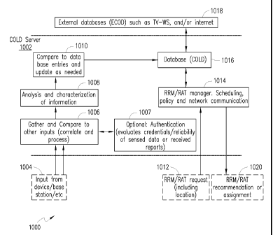
device 300 is operably coupled to the communication subsystem 304, which can
operate
with various access technologies, operating bands/frequencies and networks
(for example, to
effectuate multi-mode communications in voice, data, media, or any combination
thereof).
As will be apparent to those skilled in the field of communications, the
particular design of
the communication subsystem/module 304 may be dependent upon the
communications
network(s) with which the device is intended to operate, e.g., as exemplified
by
infrastructure elements 399 and 397.
16
CA 02808502 2013-02-15
WO 2012/037669 PCT/CA2011/050265
Microprocessor 302 also interfaces with additional device subsystems such as
auxiliary input/output (I/0) 318, serial port 320, display 322, keyboard 324,
speaker 326,
microphone 328, random access memory (RAM) 330, other communications
facilities 332,
which may include for example a short-range communications subsystem, and any
other
device subsystems generally labeled as reference numeral 333. Example
additional device
subsystems may include accelerometers, motion sensors, location sensors,
temperature
sensors, and the like. To support access as well as authentication and key
generation, a
SIM/USIM interface 334 (also generalized as a Removable User Identity Module
(RUIM)
interface) is also provided in communication with the microprocessor 302 and a
UICC 331
having suitable SIM/USIM applications.
Operating system software and other system software may be embodied in a
persistent storage module 335 (i.e., non-volatile storage subsystem) which may
be
implemented using Flash memory or another appropriate memory. In one
implementation,
persistent storage module 335 may be segregated into different areas, e.g.,
transport stack
345, storage area for computer programs 336, as well as data storage regions
such as device
state 337, address book 339, other personal information manager (PIM) data
341, and a
connect module manager including an IT policy module as well as other data
storage areas
generally labeled as reference numeral 343. Additionally, the persistent
memory may
include appropriate software/firmware 350 necessary to effectuate one or more
radio channel
sensing operations, filtering, report generation and transmission, generation
of resource-
allocation-related control messages and other COLD-related processes, etc., in
conjunction
with one or more subsystems set forth herein under control of the
microprocessor 302 or
specialized circuitry. Powered components may receive power from any power
source (not
shown in FIG. 3). The power source may be, for example, a battery, but the
power source
may also include a connection to power source external to wireless UE device
300, such as a
charger.
The radio apparatus and associated resources of UE device 300 (i.e., including
but
not limited to communication subsystem 304) may be extended,
configured/reconfigured, or
otherwise modified to enable the device to sense (or "sniff') the radio
environment without
interruption to any ongoing communications processes that may be occurring
with the
device's serving network station. Such functionality may include sensing
during idle times
between transmissions to its serving network station (or other stations) and
scheduling such
transmissions to enable sensing at times needed to detect external signals.
Accordingly, the
radio apparatus of UE device 300 may sense channel activities and radio
conditions in its
17
WO 2012/037669 CA 02808502 2013-02-15
PCT/CA2011/050265
own RATs as well as other RATs and frequency bands (e.g.. TV white spaces,
lightly-
licensed frequencies, etc.). The radio apparatus as well as any controlling
software/firmware
may be extended to effectuate measurement of the duration of the signals
sensed in a
particular radio channel of the radio environment. In a further variation, the
radio apparatus
and the associated software/firmware may be extended or configured to sense
one or more
channels substantially at the same time in addition to the channel that the
device may be
using to communicate with its serving network station. Additionally, the radio
apparatus
and the associated software/firmware of the device may be extended or
configured to include
sensing of channels that may be outside the normal set of channels used by the
device to
communicate with its serving network station. For example, a device that would
normally
communicate with its serving network station using FDD mode (where the device
is
normally equipped with a transmitter for one channel in a band to send radio
signals to the
serving network station (i.e., uplink), and a receiver for another channel in
another band for
receiving radio signals from the serving network station (i.e., downlink)),
the radio apparatus
of the device may be extended to include a receiver functionality capable of
receiving
signals in the uplink band so as to sense the uplink signals sent by other
devices that may be
nearby. Similarly, if the device is using TDD mode for its radio
communications, it may
divide its time between uplink transmissions and downlink reception. To
facilitate
additional sensing, the device may alter the timing of its receiver to enable
it to include
reception during the uplink intervals in order to sense the transmissions of
other devices.
In one arrangement, the sensing functionality of wireless UE device 300 may
comprise taking measurements of radio signals including but not limited to the
following,
inter alia: (i) The signal strength or noise level over bandwidths for the
expected signals in
the channel(s) being sensed. When there is no identifiable signal in the
channel, the sensing
process may report the "noise- strength in units such as dBm and the
bandwidth. When the
signal can be identified, the sensing process would report the "signal-
strength in units such
as dBm and the bandwidth of the detected signal. (ii) The sensed information,
when the
signal in the channel can be identified, may include the type of signal (e.g.,
the radio access
technology). The sensing measurements could also include the location of the
sensing
device, the identification of the stations (network or device) that may be
communicating and
the identification of the commercial network detected using the channel. (iii)
For some radio
signal formats, the device may estimate the "loading- of the channel, for
example, the
fraction of the time that the channel is occupied by radio signals (e.g.. IEEE
802.11 packets).
18
WO 2012/037669 CA
02808502 2013-02-15
PCT/CA2011/050265
In another variation. UE device 300 may store the sensed information for is
own
current and future use. Alternatively or additionally, the device may also
share the sensed
information with other devices or network stations when requested or by
subscription (or
some other distribution mechanism). Further, the device may receive (and
store) sensed
information from other devices or network stations (using the radio and
network
communications links with the serving network station or other devices). This
information
may be useful to the device (and optionally to other devices of network
stations) in
evaluating the radio conditions and determining what radio services to use to
communicate
using the channel currently or at some future time.
FIG. 4 is an example radio network scenario 400 where a sensing element 402
(e.g.,
a mobile communications device or UE device) may be configured to sense radio
resource
conditions in both licensed and unlicensed spectra (i.e., bands, wavelengths
or frequencies)
according to an embodiment of the present patent application. Sensing element
402 is
provided with a radio sensing/reporting apparatus 404 that in one embodiment
may comprise
one or more of the functionalities described hereinabove.
A portion of the radio
environment that the sensing element 302 is capable of sensing in its location
or area (i.e.,
the sensory region) may be populated at any one time by one or more radio
elements such
as, e.g., other wireless UE devices operating in the same or different RATs,
base stations,
and the like. By way of illustration, radio element 406 is exemplary of such a
radio element
in a non-limiting way that can communicate with one or more networks using
licensed,
unlicensed, lightly-licensed, or shared/pooled radio resources. For example,
radio element
406 may interact with network 412 using licensed resources 408 for its
downlink 410A and
uplink 410B communications. Likewise, radio element 406 may also interact with
network
418 using non-licensed resources 414 for both downlink 416A and uplink 416B
communications. Alternatively or additionally, radio element 406 may use
appropriate radio
resources for communicating with other devices (i.e., peer communications).
The radio
sensing apparatus 404 of sensing element 402 is configured to scan at least a
portion of the
RF spectrum to sense radio channels with respect to all such communications as
well as any
unoccupied channels. As illustrated, reference numerals 420A and 420B refer to
the sensory
signals received by sensing element 402 with respect to the downlink and
uplink channel
usage of radio element 406 in licensed communications with network 412. In
similar
fashion, reference numerals 422A and 422B refer to the sensory signals
received by sensing
element 402 relative to the downlink and uplink channel usage of radio element
406 in
unlicensed communications with network 418. Reference numerals 424, 426 and
428 are19
CA 02808502 2013-02-15
WO 2012/037669
PCT/CA2011/050265
illustrative of sensory signals in other RF spectra received by the sensing
apparatus 404 of
sensing element 402 that may be processed, reported, or otherwise managed for
purposes of
the present patent application.
FIGS. 5A and 5B are flowcharts of embodiments of a radio resource management,
usage and allocation scheme of the present disclosure. As set forth in block
502 of
embodiment 500A, a sensing element scans an RF spectrum for sensing data
associated with
a particular radio channel (e.g., occupancy of the channel by a radio element,
noise/interference characteristics, reliability of the sensed data, etc.). As
described
previously, the sensing element may be a wireless UE device, a base station or
eNB, a
serving network node, a relay node, a femto cell, an access point, and the
like. Based on the
detected sensory data, a radio resource may be allocated, assigned or
reassigned, or
otherwise managed for the sensing element's own use or of another radio
element, which
can be another sensing element (block 504). Additionally or alternatively, the
detected
sensory data may be reported to other sensing elements (block 506). In another
alternative
or additional arrangement, the sensory data may be reported to an external
database, e.g., a
database or server associated with a wide area IP network such as the Internet
(block 510).
In a still further arrangement, the sensory database may be reported to a
service network,
e.g., a COLD server (block 508).
As illustrated in FIG. 5B, embodiment 500B involves receiving sensory data
from
one or more sensing elements operating in one or more portions of the RF
spectrum (block
550). The received sensory data may be processed, e.g., calculation of
interferences,
correlation/comparison/combining of expected/projected channel occupancies and
durations
thereof, application of thresholds on signal strengths (for instance, pre-
assigned thresholds),
SIR/SNR measurements, error rates, as well as taking into account data
granularity and data
reliability indications, etc. (block 552). It should be appreciated that
"processing" of sensory
data may include these and other functions described below in additional
detail may be
performed in any combination, order or sequence, for purposes of the present
disclosure.
Responsive to the processed sensory data, a control message (e.g., a resource
allocation
control message) may be sent to a network (for instance, a resource scheduler
operating at an
eNB node) or to a UE device to effectuate allocation of a radio resource to at
least one radio
element operating in the radio network environment (block 554).
FIG. 6A is a diagrammatic representation of a sensory information acquisition
process 600A according to one embodiment. A sensing element 602 may be
provided with
the sensory information acquisition functionality which may be implemented as
a process
20
CA 02808502 2013-02-15
WO 2012/037669 PCT/CA2011/050265
executing on one or more control processors of the sensing element (e.g., a UE
device or
other network elements). In one implementation, the sensing element 602 may be
instructed
to sense and report sensory data pursuant to instructions signaled from the
network/COLD
server (block 604). A processing module 606 is operable to process the
instructions, sensed
radio conditions, or other observed events. A sensing scheduler 608 and a
report scheduler
618 may be configured as sub-processes of the overall sensing element process
602 wherein
the sensing scheduler 608 is mainly tasked with controlling a channel sensing
process block
610. A data accumulator process 612 may locally store and process the sensed
data that may
be used for report creation (block 614) based on control inputs from the
report scheduler 618
as well as based on previous reports obtained from storage 620. Newly created
reports or
updated reports from previous reports are provided to a transmitter process
622 that may be
configured for sending the reports to specific locations based on, e.g.,
inputs from the report
scheduler 618. The reports may be locally stored (block 620) or sent to base
stations,
network nodes and/or one or more COLD servers 624 (generally referred to as
network
elements, cumulatively), possibly via a proxy element if the sensing element
does not have
the necessary connectivity (i.e., out of coverage area).
As set forth previously, a sensor element can be instructed to send back
information
via instructions signalled from the COLD server, which can be part of the
radio
communications air interface such as sensor-specific or cell broadcast
transmissions, or can
be achieved by application-layer signaling (i.e.., "over¨the-top" or OtT type
signaling, e.g.,
that may utilize TCP/IP or forms of the Short Messaging Service (SMS) or
Multimedia
Messaging Service (MMS)). The sensor element can also be instructed to report
specific
information in response to a query message from the COLD server. Further, a
request may
be configured to initiate a series of report events from the sensor element.
In one embodiment, the sensor element can be configured to sense and report
radio
environment information autonomously during some specific condition, such as
when using
a channel with specific characteristics. For example, the sensor element can
be configured
to communicate sensory information and location information to the COLD server
when
using spectrum that is shared, pooled, or unlicensed. In another embodiment,
the sensing
element processes and in particular those associated with the mobile devices
may be
instructed to report on the interference and usage in select shared channels
only. The sensor
element may recognize such a requirement of providing the information from a
default
configuration that is activated when the mobile device is operating in shared
channels or by
21
WO 2012/037669 CA 02808502 2013-02-15 PCT/CA2011/050265
some signaling (such as broadcast messages, or System Information or Master
Information
Block (SIB/MIB) messages in LTE systems, for example) from the radio
communications
network such as when instructed to use a particular carrier or band. This
signaling may take
the form of OtT signaling, an indication in a broadcast message of the cell,
or in sensor-
specific information.
In an additional embodiment, the sensor element may be triggered to sense and
report radio environment information based on a change in conditions. For
example, a
sensor element may be configured to recognize when the interference level of a
communications channel exceeds some threshold. In one implementation, this may
be
determined by measuring the interference level directly and comparing to a
threshold. In an
alternative embodiment, a ratio may be measured (e.g., SNR or SIR) and
compared to a
threshold. A feedback signal may be triggered when the applicable ratio
crosses a given
threshold. In yet another embodiment, the sensor element may be triggered when
the
communications channel is degraded beyond a threshold based on one or more
performance
metrics including but not limited to supportable modulation and coding schemes
(MCS),
supportable data rate, received signal strength, etc. The sensing process of a
sensor element
may be configured to be triggered when one or more of above conditions are
satisfied such
that the sensor element may communicate its sensory data reports to a COLD
server. In
addition, the sensor element may continue to sense the channel and report only
when the
conditions change from the last sensing interval or period, or alternately,
from the last
transmitted report. The conditions for reporting can be configured in the
sensor element by
broadcast messages signaled by the communications network or can be sent via
OtT
signaling by the COLD sever.
In some embodiments each sensory data report from the sensing element can
contain
information of the most recent sensory event (which may be triggered by the
initiation of a
report itself). In some additional variants of this implementation, the
sensory data report
may also include information accumulated since the last reporting event or
accumulated over
some predetermined time window (e.g., a fixed time period or a sliding time
window). In a
further variation, the information sensed and recorded between reports can be
expressed
and/or reported as average values over the period for a given metric. Other
variants of this
implementation may include expressing the sensor information as a log of a
series of values,
statistical representations of processes observed (including variance,
cumulative and
probability density distributions, etcetera). In yet another embodiment, the
sensing cycles
22
WO 2012/037669 CA 02808502 2013-02-15 PCT/CA2011/050265
and reporting cycles may not be aligned. For example, the sensing may occur
opportunistically at irregular intervals (as may be scheduled by the sensing
scheduler 608),
while reporting can occur when determined by a regular schedule (based on the
reporting
scheduler 618).
In some implementations, the mechanism for initiating sensing events may be
based
on one or more of the following features. (i) When a channel measurement is
made or
becomes available: For example, channel quality indication (CQI) feedback may
be sent as
part of regular operation in a cellular system such as Wi-MAX, LTE etc. At
every interval,
or alternatively, every nth interval as configured, a sensing operation may be
configured to
coincide with the CQI measurements). (ii) Device is or becomes idle: In this
embodiment,
sensing is only performed at intervals when the device is not sending or
receiving traffic.
(iii) Change in radio resource allocation to different carrier, band, or
licensing/administrative
region: For example, sensing operations may be configured to coincide with one
or more of
changing from GSM to a 3G connection, or 3G to IEEE 802.11a/b/g, or changing
from 2.4
GHz band to 5 GHz band in IEEE 802.11 operation). (iv) A reporting event
occurring: In
this implementation, a sensing event is initiated each time a report event
occurs. For
example, a report event may be scheduled every 10 seconds. After each time a
report is
sent, the sensing event begins. The duration of the sensing event and time
needed for
processing of the information may be configured to fit in the report interval.
(v) Periodic
time interval: For example, a sensing event is regularly scheduled to occur
every "x"
seconds. In some variations, the sensing events may only be completed if the
device is a
specified mode, for example, an active mode.
In similar fashion, reporting events may be initiated based on one or more of
the
following features. (i) Sensing event occurred: In this implementation, a
report event is
initiated at the end of a sensing event. In further variations of this
implementation, the report
may include information accumulated over multiple sensing events. (ii) Change
in sensed
data: In this variation a reporting event is initiated when channel conditions
change beyond a
configured threshold as illustrated by examples set forth previously. (iii)
Periodic time
interval: For example, a reporting event is regularly scheduled to occur every
"y" seconds.
In some implementations, the reporting events will only be completed if the
device is in a
specified mode, for example, an active mode. (iv) Device is idle: In this
variation, reporting
is only performed at intervals when the device is not sending or receiving
traffic. (v)
Transmitting other information to network or base station: In this aspect,
reporting is
23
WO 2012/037669 CA 02808502 2013-02-15 PCT/CA2011/050265
initiated to be transmitted with other information being sent via the uplink.
In an additional
variant, a timer may be introduced to specify an interval over which the
device does not send
a report unless other information is sent on the uplink. If other information
is sent by the
device on the uplink during the interval, the report is sent with the other
information and the
timer is reset.
As mentioned previously herein, the information sensed and reported from the
sensing element or device may include the location of the device, time of
detection, range of
spectrum and strength of the signals, among others. The time of detection may
allow the
COLD server to identify whether the reports of interference from sensing
elements belong to
the same interference burst or the same interference sources. In some
implementations the
mobile device need not do sensing or detection separately from its normal
operation. For
example, the mobile device may regularly conduct the detection of channel
quality, and may
simply report this parameter when queried by the COLD server. In one
embodiment, the
sensing device may be able to, instructed to, and/or configured to identify
the signal by type
(e.g., noise, TV signal, 802.11, CDMA-1S95, LTE, unidentifiable, etcetera)
and/or network
type/ID and include such information in the report to the COLD server. As
pointed out
earlier, the sensing device may also identify the type of RAT(s). Such an
operation may be
simplified for the device if the detected signal is a RAT supported by the
sensing device.
The sensing device may therefore additionally identify the signal as
originally from its own
radio communications network (i.e., the network to which the UE device is
currently
reporting) or a different radio communications network. Other information may
also be
requested (and/or reported) in the sensory data report including the bandwidth
and/or center
frequency of the signals detected. For example, a 3G/2G device using Network A
can be
instructed to report 2G/3G base stations sensed in the area, the network(s)
they are identified
with, received signal strength indicator (RSSI) and the bands on which they
are transmitting
any broadcasting access information. The sensory data reports may also include
details
regarding broadcast information (available from MIB and/or SIB messages in an
LTE
network implementation, for example, or similar broadcast channels) such as
active primary
and secondary carriers. Further, the sensing device may be configured to
report interference
on bands that exceed a threshold on energy level, or where the base station or
transmitter
cannot be properly identified. In some cases to limit the volume of reporting,
some sensing
devices may be configured to exclude the RAT or signal type information from
the sensory
reports. In other cases, only the interference level in the band(s) may be
reported.
24
CA 02808502 2013-02-15
WO 2012/037669 PCT/CA2011/050265
Optionally, the bandwidth and nature of the time duration of the interference
(e.g. 1 ms
burst, continuous, bursty with 50% duty cycle, etcetera) may also be reported
depending on
the sensing device's capabilities and/or the inquiry messages from a COLD
server.
In general a sensory data report may include one or more of the following
items, or
any combination thereof: (i) device location; (ii) time stamp, or
alternatively, report number;
(iii) interference level; (iv) interference signal bandwidth; (v) band and/or
channel (which
may be a band instructed in the report request); (vi) center frequency of
signal; (vii) signal
type (TV, noise, cellular, etcetera); (viii) mobile communications RAT(S);
(ix)
network/system identification; (x) transmitter station identification; (xi)
duty cycle of signal;
(xii) expected duration; (xiii) location of receivers (which may include
mobile devices);
(xiv) sensor identification or authentication; and the like. Additionally, the
sensing element
may also sense and/or report further parameters of the interference including:
(i) FDD or
TDD operation; (ii) TDD UL/DL partition ratio and/or timing, etc.
In one aspect, the sensory data information may be gathered from sensing of
activity
of the signal where determining the sources or the type of signaling
(including, e.g.,
modulation method, multi-user or single-user sources, etc.) at different times
in the observed
frame may indicate FDD or TDD operation, and if TDD, the partition ratio. In
another
embodiment, such information may be gathered at the sensing device by
acquisition,
detection or decoding of a broadcast channel (such as MIB and/or SIB's in LTE
systems) or
some other signaling that indicates the system parameters. In a further
variation, the sensing
element may be configured to estimate for how long the interference measured
is expected
to be valid (i.e., valid duration). Such information can be useful in
processing reports by
including only reports that are valid (i.e., within their valid duration), and
decaying of the
weighting factor user in combining multiple reports conditional on the age of
the report. In
one variation of the embodiment, the sensing element may observe the duration
of channel
occupancy over a longer window (which may be several frames). For example, the
sensing
element may estimate that the traffic is due to bursty users by observation
over a longer
window, and indicate the valid duration of the interference report as
relatively short-term. In
another variation, the sensing element infers the valid duration of the
information from the
identification of the source or source type. For example, in another location,
a sensing
element may observe a type of traffic that is expected to be in use longer-
term such as a TV
station.
In some additional embodiments, the sensing element report may also include
25
CA 02808502 2013-02-15
WO 2012/037669 PCT/CA2011/050265
location of receivers, where the sensing element may identify receivers
through signaling or
be aware of the receiver(s) from direct communications or broadcast
communication. If
available, the report can contain parameters (band, bandwidth, type, etc.) of
the signal the
receiver is intended to receive. For example, if a reporting device is engaged
in dev ice-to-
device communications, it may report details of the other device as well so
that the database
is aware of both transmitter and adjacent locations which are to be protected
from
interference. In some embodiments, the sensor or sending element may also
include its own
identity so that the origin of the report may be traced and calibrated. For
example, the
sensing element may indicate its unique ID in the report. In another
embodiment, the sensor
identification may be replaced by a method for authentication such as a
certificate or pass
code which may be represented as a sequence included in the message, usage in
the
encoding/encryption of the message, or alternatively in the scrambling of the
message after
encoding. In a variation of this last embodiment, the identification may
contain both a
portion associated with the device ID, and another portion consisting of
certificate or pass
code. The two portions may be sent as composite ID through concatenation, or
other
combining methods. As will be set forth below in further detail, such
information from the
sensing elements may be used at a COLD server process for authentication,
verification and
possibly for filtering of sensory data reports before updating any sensory
database(s).
In another aspect, the sensory report itself may be expressed as indexed
results from
a lookup table of possibilities. For example, the interference levels can be
quantized so that
they can be expressed as an N-bit value. Other table indices can be used to
represent the
other category values. In some cases, in order to minimize the information
transmitted, the
fields transmitted may be expressed as a differential (or a "delta-) from the
last report
transmission. In some cases, only those fields that have changed may be
included in the
report. The report can also contain and index at the beginning of the report
to indicate which
fields are included in the report. In some implementations, a report of
absolute values (i.e.,
non-differential) can be sent periodically, or on-demand to reduce the effect
of propagation
of errors due to missed reports. By observing the report number, or tracking
the arrival of
expected periodic reports, the network and COLD server may also be able to
determine
when a report was missed.
In another implementation with respect to reporting, the value of one of the
fields
other than the report type index may be configured to indicate what is
represented in the
other fields of the report or how the rest of the report is to be interpreted.
For example, the
26
CA 02808502 2013-02-15
WO 2012/037669 PCT/CA2011/050265
report may contain different fields, and even be different lengths for
different report types.
For a specific report type (e.g., 0001), the field "signal type- may be
presented with possible
values as follows: 1: TV type 1; 2: TV type 2; 3: Mobile Cellular 802.16; 4:
Mobile Cellular
LTE; 5: Mobile Cellular IS-95; 6: Mobile Cellular HSDPA; 7: Mobile Cellular
GSM; and 8:
Unknown. The fields that comprise the rest of the report may be of a similar
or same
configuration if values 1-7 are transmitted. However, different field
configurations may be
present in the report if the example value "8- is indicated.
A sensory data report may also include a reliability indication with respect
to any
piece of the sensed/reported data, e.g., the interference value or other
information. The
reliability indication may be provided as a statistical measure of the
confidence level that
interference has been correctly characterized by the reporting, or
alternatively the sensing,
mechanism(s). In one implementation, the reliability indication or value may
indicate the
confidence that the RAT has been correctly identified. In another embodiment,
the
reliability value may provide an indication that the interference has been
correctly identified
as a communications signal and not noise. In this embodiment, the reliability
value may be
a measurement of the interference level. In another embodiment, the
reliability value may
also indicate the error tolerance in the measurements (for example +/- 10%, or
location
within +/- 50 meters, and the like). In yet another embodiment, the
reliability indicator(s)
included in the report may be based on the channel conditions under which the
report was
created, including but not limited to: SNR/SIR, error rates, duration of
measurement
interval, etc., or the equipment and/or method used to make the measurement,
or the
confidence of the results/measurements. In some embodiments, the database may
also use
the identity of the sensor as a factor to assess the reliability of the
sensing report based on
past reports, local phenomena around that sensor, or other information.
In some embodiments of a radio network environment, it is possible that not
all
sensing devices are in contact with the communications network. Some may be
able to
participate in device-to-device communications and be in range of another
device that is
connected to the network. In some cases, a device that is not connected to the
network can
send its sensory information to another device (that in and itself may or may
not have the
sensing capability), which can then be forwarded to the communications network
and the
COLD sever (i.e., proxy reporting). FIG. 6B is an arrangement illustrative of
a sensory
information reporting process by proxy according to one embodiment 600B of the
present
patent application. Mobile device 650A is illustrative of a device (e.g., a UE
with multi-
27
WO 2012/037669 CA 02808502 2013-02-15
PCT/CA2011/050265
RAT/multi-channel sensing capability) within a wide area cellular network
having
connectivity with network infrastructure 652 via a communication path 666.
Mobile device
650B is illustrative of a sensing device without such wide area cellular
connectivity. It
should be realized that either mobile device 650A or mobile device 650B, or
both, may be
implemented as a wireless UE device 300 described in detail hereinabove. By
way of
illustration, as exemplary sensing devices, each mobile device comprises
respective sensing
modules 656A, 656B; reporting modules 658A, 658B; processing modules 660A,
660B; and
local database modules 662A, 662B. Each device may also include respective
antenna
arrangements 654A and 654B with respect to wide area cellular communications
or other
radio communications. Additionally, each device also includes appropriate WiFi
radio
apparatus 664A and 664B whereby an ad hoc or direct WiFi communication path
668 (e.g.,
via device-to-device communications using short-range RF communication) may be
established between the devices for sending the sensory data sensed by mobile
device 650B
that does not have WAN radio access. Accordingly, mobile device 650A acts as a
"proxy
device" for reporting the sensed data to the network on behalf of mobile
device 650B.
Furthermore, where mobile device 650B is instructed to provide sensory and
location
information via signaling, such instructions/messages may be relayed to it via
the directly
connected device, i.e., mobile device 650A. In one embodiment, when one device
(mobile
device 650B in FIG. 6B) comes back into suitable WAN/network access range, its
own
sensing/reporting may take over and the proxy service via WiFi communication
with mobile
device 650A may be terminated or otherwise superseded. However, as long as
mobile
device 650A operates as a valid proxy agent for mobile device 650B (i.e.,
relaying sensing
information of mobile device 650B to and from the network), it may aggregate
its own
sensing information with the sensory data from mobile device 650B before
communicating
with the network. Likewise, mobile device 650B may also aggregate its own
sensory data
into batch reports to be sent to mobile device 650A (i.e., batch mode
transmission). Such
transmissions may be performed responsive to, for example, (i) receiving a
request from
mobile device 650A or from the network (via device 650A) for the sensory data,
(ii)
detecting a change in a radio condition in the sensing area of mobile device
650A or 650B,
(iii) mobile device 650B commencing operation in a shared radio frequency
band, (iv)
mobile device 650B changing operation from one radio frequency band to another
radio
frequency band, (v) passage of an idle period of a predetermined duration, and
(vi) passage
of a predetermined periodic time duration, and the like.
28
CA 02808502 2013-02-15
WO 2012/037669 PCT/CA2011/050265
Based on the foregoing, an exemplary implementation of a method operable with
a
wireless UE device that requires proxy reporting may be set forth as follows.
As described
previously, the UE device, although may not have any coverage with respect to
a wide area
cellular network, is capable of scanning multiple radio frequency spectra for
detecting
sensory data associated with multiple radio channels relative to at least one
radio element in
within its sensing area. A determination may be made if the wireless UE device
is out of
range of a wide area cellular network; and responsive to that determining, a
short-range
wireless communication path may be established with another wireless UE device
having a
wide area cellular communication connection. Thereafter, the wireless UE
device
commences transmitting the sensory data to the other wireless UE device (i.e.,
proxy) for
reporting to a network element associated with the wide area cellular network
(e.g., a base
station, an eNB node or a COLD server). It should be realized that the
software and
hardware resources of the wireless UE device (e.g., processors, memory, I/O
communications subsystems, etc.) may be adapted as components configured to
perform the
foregoing acts in accordance with overall processor control.
As pointed out previously, in some embodiments sensory information may also be
reported from network element access points such as base stations, eNB nodes,
relays, femto
cells, sensing stations, etc. that communicate with the radio communications
network and
the COLD server through wireless and wired connections. For purposes of the
present
patent application, the term "base station" is used as a general
representation for any of such
"fixed" sensing elements. FIG. 7 is a diagrammatic representation of a sensory
information
acquisition process 700 according to one embodiment wherein a network node 702
(e.g., a
base station) is operative as a sensing element. In some configurations of the
embodiment,
the base station may be queried to sense and/or provide reports on radio
conditions such as,
e.g., channel usage and interference. As illustrated, such querying may
emanate from the
network or a COLD server (block 704). In other configurations of the
embodiment, the
base station process may also sense and/or provide scheduled reports to the
network or
COLD server, and/or be configured in such way that conditions of the channel
and/or
network may trigger a report or sensing event. In an embodiment similar to the
UE device
sensing and reporting process described in the foregoing sections, the base
station process
702 can report on the channel occupancy and interference levels in one or more
bands or
spectra. A processing module 706 is operable to process the network/COLD
instructions,
sensed radio conditions, or other observed events. A sensing scheduler 708 and
a report
scheduler 718 may be configured as sub-processes of the overall base station
process 702
29
WO 2012/037669 CA 02808502 2013-02-15 PCT/CA2011/050265
wherein the sensing scheduler 708 may be tasked with controlling a channel
sensing process
block 710. A data accumulator process 712 may locally store and process the
sensed data
that may be used for report creation (block 714) based on control inputs from
the report
scheduler 718 as well as based on previous reports obtained from a storage
720. Newly
created reports or updated reports from previous reports are provided to a
transmitter process
722 that may be configured for sending the reports to specific locations based
on, e.g., inputs
from the report scheduler 718. The reports may be locally stored (block 720)
or sent to
network locations (e.g., other base stations or network nodes tasked with RRM
functionalities, etc.) and/or one or more COLD servers, as exemplified in
block 724.
As the base station may have more power and equipment resources, the radio
apparatus and associated resources may be configured to sense several channels
simultaneously or intermittently, and hence may be able to provide at least
the level of
sensory and channel information as described in the earlier sections relating
to the UE
device sensing/reporting process. Because of additional processing power, the
base station
may also be capable of better characterization of the interference in each
channel including
the type of signal and RAT. In some embodiments, base stations may be
configured to
detect and report information on RATs that are not supported for access by the
base station.
In addition to advanced sensing of channel occupancy and interference, the
base
station process 702 may also be configured to report its own channel usage or
RRM
information to the network and/or COLD sever. With this information, the COLD
server
may be able to correlate the usage information with other sensing/interference
reports in
order to properly identify and/or confirm the identity of interference
sources. In one
variation of this embodiment, the base station can report when a different
carrier is used
(such as, e.g., an LTE carrier). In another embodiment the base station may be
configured to
report changing the bandwidth of a carrier (such as, e.g., an LTE carrier). In
a still further
embodiment, the base station or access point may be configured to report
changing to a
different channel, or even different band (such as, e.g., a WLAN AP changing
from 2.4 GHz
to a 5 GHz band and channel). In another embodiment, information can be
reported to the
COLD server wherever and/or whenever the scheduling information is available.
For
example, the base station can report the assignment of persistent resources
to/for a mobile
user, or assignment of a frame, slot or carrier as one used for multi-cast
broadcast services
(MBS). Such information may contain information of future scheduling events
and details
of the interference expected with respect to any surrounding systems.
30
WO 2012/037669 CA 02808502 2013-02-15 PCT/CA2011/050265
In yet another aspect, a base station may be configured to request
information, or
pass on a request for information to a device in its serving region. FIG. 8 is
a diagram
illustrative of a process 800 wherein a network node (e.g., base station 802)
passes requests
for sensing to a UE device according to one embodiment of the present patent
application.
As illustrated, base station 802 includes one or more sub-processes, modules
or functional
blocks for effectuating the request handling/passing process 800. A MAC/PHY
processing
block 806 is operative to process signals received from a UE device over
control or data
channels such as, e.g., PUCCH, PUSCH or RACH channels in an LTE network (block
804),
as well as control signals provided by a MAC/PHY request signaling process
block 816
which is operative to send requests to a UE device over control/data channels
such as, e.g.,
PDCCH/PDSCH channels of an LTE network (block 818). The MAC/PHY processing
block 806 is configured to provide appropriate information to a report
creation block 808
which interfaces with a report database 812 as well as a report scheduler 814.
In addition,
the base station process 802 may include a packet processing block 820
configured to
process packets received from the network, COLD server(s) or other base
stations or devices
as well as a resource request processing block 826 that is configured to
process and route
radio resources requests from a UE device towards a network node, COLD server,
or other
RRM entity (as illustrated in block 810). Some of the foregoing
functionalities are set forth
in additional detail hereinbelow.
As shown in FIG. 8, the process of requesting reports from a UE device may be
initiated in several different ways, e.g., from the network and/or COLD server
or base
station or another device as exemplified in block 813. The request may be
initiated from the
network or COLD servers using, for example, OtT signaling. Such a request may
be sent in
a packet to the UE/mobile device after being scheduled by the base station's
RAT. In some
embodiments, the request may be initiated from the network or COLD severs and
be
signalled to the base station to gather sensory information. In some
embodiments this
process may include the base station signaling of the UE device through either
a control
channel or an embedded data channel. For example, as mentioned above with
respect to an
LTE-type system, the request may be indicated by a modified type of physical
downlink
control channel (PDCCH) or sent in a packet over the physical downlink shared
channel
(PDSCH) (block 822). Likewise, a resource request or a sensory report from the
UE device
towards the network or COLD server may be indicated via a modified channel
such as a
PUSCH channel (block 824). In an alternative embodiment, the base station
itself may
31
WO 2012/037669 CA 02808502 2013-02-15 PCT/CA2011/050265
request the sensing and/or reporting from the UE mobile device and also send
the request
using suitable control and/or data channels as described above. In a further
variation of this
embodiment, the base station may initiate the requesting process in order to
gain information
for a sensing report either requested or scheduled by the network or COLD
server.
In some embodiments, a UE device may be configured to report sensory
information
directly to the base station 802. The sensory information from the UE device
is processed
by the base station's MAC/PHY processing if received over the uplink control
channel or
passed in an uplink packet intended for the base station. As mentioned
previously with
respect to an LTE-type system, the report may be indicated by a modified type
of physical
uplink control channel (PUCCH), sent in a packet over the physical uplink
shared channel
(PUSCH), or sent using packets over the random access channels (RACH), as set
forth in
block 804. The base station 802 can relay the raw sensory information from the
UE device
directly to the network node or COLD server, or may include additional
information from
other sensor reports (including reports generated by the base station itself).
In generating a
report for the COLD server from the UE device report(s), the base station 802
may process
some of the information including correlating reports from one or more UE
devices, and
possibly information from the sensing of the base station itself, in order to
determine a more
reliable estimation of the channel occupancy and interference data. The base
station 802
may also use the reliability estimates from the sensory reports to properly
weight the reports
when processing (e.g., combining) the information. Such processes may be
exemplified in
the report creation block 808. In an alternative variation, the UE device may
send its
sensory report in one or more packets directed towards the COLD server using
OtT
signaling. In at least this configuration, the sensory reports from the UE
device may be in
response to, but not limited to, a request sent via OtT signaling.
In another aspect, a base station may also be configured as a point of
exchange of
radio resource allocation commands and radio resource requests from a COLD
server and
UE devices, respectively. FIG. 9 is a diagrammatic representation of a process
900 that
illustrates exchange of commands or messages at a base station 900 relative to
radio
resource allocation in one embodiment. Similar to the base station processes
described
above, base station 902 includes one or more sub-processes, modules or
functional blocks
for effectuating the overall exchange functionality set forth herein. A radio
resource request
routing block 906 is operative analogous to the block 826 of FIG. 8 for
receiving and
processing/routing resource requests emanating from a UE device via OtT
signaling (e.g.,
32
WO 2012/037669 CA 02808502 2013-02-15 PCT/CA2011/050265
network packets in uplink channels such as PUSCH channels as illustrated in
block 904). A
MAC/PHY processing block 912 is operative for processing resource requests
emanating
from the UE device via modified uplink channels (e.g., PUCCH, PUSCH or RACH
channels
as illustrated in block 910). A sending block 914 is operable responsive to a
base station
traffic scheduler 916 in conjunction with the output of MAC/PHY processing
block 912 for
sending the processed radio resource requests to the network and/or COLD
servers, as
illustratively exemplified in block 908.
Radio resource availability messages from the network and COLD servers (as
exemplified in block 918) are processed for scheduling of radio resource
assignment (block
920), which interfaces with a MAC/PHY signaling/scheduling block 922 for
transmission of
allocation messages to the UE device. As exemplified in block 924, such
allocation
messages may be effectuated via downlink channels such as modified PDCCH and
PDSCH
channels to the UE device. Radio resource assignment messaging from the
network and/or
COLD servers (block 926) may be handled via two mechanisms. In one mechanism,
the
resource assignment messages may be processed by MAC/PHY signaling/scheduling
block
922 for transmission to the UE device as described above. Alternatively, the
radio resource
assignment messages may be routed by a routing block 928 for transmission to
the UE
device via OtT signaling (as network packets in a downlink channel such as a
PDSCH
channel, as exemplified in block 930).
It should be appreciated that although the base station 902 in one embodiment
may
handle all of its radio resource management functions within a given channel,
in some
embodiments as described herein the COLD server may be queried for channel
suitability, or
in a further variation of the embodiment, the COLD server itself may allocate
radio
resources. Accordingly, in some embodiments the COLD server may be configured
to
determine available channels based on the sensory information received. In
such an
implementation, channel availability may be chosen based on characteristics
such as, e.g.,
interfering beyond operating parameters with respect to the operation or
coverage of primary
users, whether or not certain channels are fully loaded, or otherwise have
unacceptable
levels of interference or activity, and the like. Additionally, in some
embodiments, the
COLD server may further consider a "best" channel, e.g., a channel determined
as having
the least interference, or best performance, or lowest cost that is available.
As described elsewhere herein, requests for radio resource allocations may
originate
from a UE mobile device (through OtT signaling or through PHY/MAC control and
data
33
WO 2012/037669 CA 02808502 2013-02-15 PCT/CA2011/050265
channels), or from the base station. Such requests may be relayed to the COLD
server, and
depending on the configuration the COLD server may indicate one or more of:
(i) a
suggested resource assignment; (ii) available channels; (iii)
approval/disapproval of
requested resource assignment; (iv) assignment of radio resources; (v)
restrictions of radio
resource assignment or usage. In one embodiment, the COLD server may be
configured to
indicate or otherwise suggest a resource assignment based on the request. For
instance, the
assignment may be based on the requirements specified in the request, such as,
e.g., one or
more of RAT(s), bandwidth, and/or service request. In an alternative
embodiment, the
COLD server can provide a list of possible candidate channel assignments that
satisfy the
requirements set forth in the resource allocation request. In a further
variation, the COLD
server may be configured to provide a response that approves or disapproves of
the request
for channel by a UE device. For example, the COLD server may disapprove of a
channel
assignment request if the channel is "unavailable" or expected to become
unavailable for the
duration of the requested channel occupancy. In a still further variation, the
COLD server
may assign a resource assignment based on a request and its requirements, and
thereafter
update an assignment database so that future assignments to another device do
not conflict
with the assignments already made or currently active. In another embodiment
that may be
used in conjunction with other embodiments set forth herein, the COLD server
may be
configured to provide a message indicating one or more restrictions as to the
usage of a
particular radio channel. For example, the COLD server may provide
restrictions with
respect to the range, distance, or other geolocation of the use of the
channel. Additionally,
alternatively or optionally, the COLD server may also restrict certain
transmit parameters of
the transmission. For example, in one variation the COLD server may restrict
the RAT that
a device is to use in a particular channel. In another variation, the COLD
server may restrict
the maximum transmit power the device can use in the channel. In some
embodiments
where the resources have been assigned by the COLD server, the base station
902 may
communicate the resource assignment to the UE device(s) via control/data
signaling
channels, OtT signaling, and the like depending on the configuration, as
described above. In
other embodiments where the response from the COLD server did not include a
radio
resource assignment (e.g. channel availability, etc.), the base station 902
may be configured
to process the information from the COLD server and complete the radio
resource
assignment as applicable.
34
WO 2012/037669 CA
02808502 2013-02-15
PCT/CA2011/050265
FIG. 10A is a diagrammatic representation illustrative of exemplary processes
1000
at an embodiment of a COLD server 1002 of the present patent application for
effectuating
one or more of the COLD server features described hereinabove. A
comparison/correlation
sub-process, module or functional block 1006 is operative in response to
sensory inputs and
other reports from UE devices, base stations, access points, other network
nodes, and the
like. As an optional implementation, authentication block 1007 may be provided
for
evaluating credentials and/or reliability of the sensed data and other
received reports. Such
authentication may be performed as part of or prior to comparing the data
and/or reports and
performing appropriate correlations as may be warranted. An analysis module or
sub-
process (block 1008) is provided for analyzing and characterizing the
processed data from
the comparison/correlation module 1006. An updating module or sub-process
(block 1010)
compares and updates data as may be needed, which is then provided to a
database (block
1016). An entity responsible for RRM, scheduling, assignment and policy (block
1014) is
operable responsive to RRM requests (as exemplified in block 1012) and the
stored data
1016 for providing suitable RRM recommendations, assignments, etc. to UE
devices, base
stations, other network nodes, as exemplified in block 1020. Additionally, the
database
1016 of COLD server 1002 may be interfaced with external databases such as
those
associated with a TV white space system, the Internet, and the like, as
exemplified in block
1018. Based on the foregoing, it should be appreciated that the COLD
server 1002 in one
embodiment may be configured to collect information from various sensory
elements of the
network to determine regional/local channel occupancy at any given time. The
database
1016 may be configured to contain a map of information indicating the times
and locations
of channel occupancies, among others. As described elsewhere in the present
disclosure,
such information may be gathered from sources including network sensor element
reports,
network activity/channel usage reports, and external information and
databases. As to the
organization of the database structure, there may be several alternatives that
may be
combined in different ways depending on implementation. In one embodiment, the
database
may be organized by sources and receivers of various types, including but not
limited to UE
devices, access points, microphones, base stations, etc. In this embodiment,
each transmitter
or receiver known to the database is identified as an entry or record in the
database, wherein
each entry may contain one or more of the following fields: (i) location; (ii)
transmit power;
(iii) band/channels of use; (v) signal type (TV, noise, RADAR, cellular RAT,
etc.) for each
band/channel; (vi) network/system identification; (vii) transmitter station
identification;35
CA 02808502 2013-02-15
WO 2012/037669 PCT/CA2011/050265
(viii) expected duration; (ix) reliability of reported information; and the
like. In another
embodiment of the database, the information may be organized based on
entries/records for
channels and locations. As described previously, the sources/locations of
interference may
be determined based on the sensory data reports and reporting range of the
sensor elements
of the network. In a further variation, the entries of the database contain
one or more
parameters including, for example: (i) channel; (ii) location; (iii)
interference level; (iv)
signal type or RAT; (v) duty cycle; (vi) source; (vii) reliability of reported
information; and
the like. In yet another embodiment, a combination of transmitter/receiver
databases and
channel occupancy databases can be used. Additionally, as mentioned previously
herein, the
database may be configured to interact with other databases to gather
information from
external sources so that a local copy of the external information may be made
available at
the COLD server 1002.
Taking reference now to FIG. 10B, additional details with respect to the
processes set
forth in blocks 1006 and 1008 may be described. The COLD server 1002 is
operable to
gather sensory information via methods including sending of explicit requests,
scheduled
requests, or by sensor configurations that are triggered to sense and/or
report upon a specific
set of conditions. In one implementation, reports from multiple sensors may be
gathered,
which can be correlated so that the same signal is not mapped multiple times,
and its full
extent can be determined (e.g., block 1052). Appropriate reliability weights
may be applied
before a correlation analysis is performed. The process of correlation may
involve
comparing the interference received at different times from different sensor
reports.
Commonalities in the reports can be seen as belonging to the same source.
Other
information can also be extracted for making such comparative analysis, which
may include
determining the signal's source and coverage. For example, if two or more
reports identify
an interference burst from the same source (by comparing the time of the
interference and
other characteristics of interference such as duration, bandwidth, etcetera),
the level of
interference power can be used to approximately determine the distance of the
source from
each sensor. By comparing such data, and averaging out time variations, an
approximate
location for the source can be estimated. The foregoing functionalities may be
illustrated as
blocks 1054 and 1056, for example.
In one arrangement, both "hard" combining and "soft" combining of reports may
be
incorporated to improve reliability of detection (block 1058). Also, in the
case of
determining an identity of an interference source, particularly bursts (e.g.,
when scanning for
36
WO 2012/037669 CA 02808502 2013-02-15 PCT/CA2011/050265
RADAR signals or occasional channel usage), the reports of time can be used to
distinguish
such signals from noise. In one variant of this embodiment, the reports for
multiple sensors
may be compared to verify that a burst received was in fact a source and not
spurious noise.
In another variant, the reports may be "soft-combined" (which involves
combining weighted
soft samples using a known technique) to improve the reception of the received
signal, and
allow a higher probability of successfully identifying the signal as (i) other-
than-noise, and
(ii) the identity of the transmission source (e.g., TV, RADAR, cellular RAT,
etcetera).
Reports can also be processed in other ways including soft-combining of
sensory
information to improve reliability through diversity, or using multiple
reports to determine
the location of interferer or the extent of its interference by determining
interference strength
contours. Directional information may also be useful in combining such
measurements to
locate the source of the signals that have been sensed. For example,
directional information
obtained by the sensor may specify the direction from which the signal was
received. The
COLD server 1002 may make use of reliability information provided or inferred
to
appropriately weight different sensing reports when processing database
updates.
In some embodiments, during analysis of the information, the COLD server 1002
may also determine that critical information is absent or unreliable and
request additional
reports from the reporting or other sensory devices. In this way, the COLD
server 1002 may
assess the coverage and completeness of its channel occupancy and radio
conditions
database, and generate suitable queries to address any deficiencies. For
example, in the
process of determining the feasibility of channel assignment the COLD server
1002 can
determine that information regarding the interference due to a specific source
is unknown,
unreliable, or outdated in a given region. The COLD server 1002 may request
specific
information from a nearby sensor node to address this deficiency. In another
embodiment,
the COLD server 1002 may also use the processed sensory information to trigger
distribution of the information to other nodes that need it or may be affected
by such
information. Such nodes may have, for example, subscribed to receive reports
involving
certain frequency bands, levels of interference, signal types detected, or for
certain
geographic regions. For instance, according to one or more of the embodiments
described,
the COLD server 1002 may identify: (i) a location for a source of
interference; and (ii)
characteristics regarding the transmission from that source. Such information
may be
distributed to UE devices or nodes in the vicinity of the source.
The processed information may be provided to the analysis block 1008 as shown
in
37
WO 2012/037669 CA 02808502 2013-02-15 PCT/CA2011/050265
FIGS. 10A and 10B. The overall functionalities of the analysis block 1008 may
include,
inter alia, source triangulation using signal power, angle of arrival, or both
(block 1060), in
addition to source identification, source location as well as characterization
of source
transmission (as exemplified by blocks 1062, 1063 and 1064). Processed reports
on source
activity and processed characterization of interference at the sensor (or
other location) may
be interfaced/updated to existing databases, which may include comparison to
and
combining with existing entries. The foregoing functionalities are exemplified
in blocks
1066, 1068 and 1070).
The COLD server 1002 may also make use of when the information was recorded
and for how long it is expected to be valid (i.e., duration). Such information
may be useful
in processing reports in view of correlated reports that were recorded at the
same time from
different sources, and also to decay the relevance of the reports as the time
since the
measurement increases conditional to the expected duration of the
interference. For
example, database information of interference that was due to short-term
traffic may be
considered with less reliability, or discarded after some time in comparison
to newer reports.
In general, the total information gathered and processed may be used to update
the database,
whereupon such information may be queried by the various elements of the
network for
purposes of radio resource management throughout the network.
In certain aspects, the COLD server database 1016 may be used as either a
complementary radio resource database or as an integral part of the RRM system
of an
existing mobile communications network. In other aspects, the COLD server 1002
may act
as a supervisor of the RRM systems operating in diverse locations and networks
(e.g., with
different RATs and having overlapping coverages). The COLD server 1002 may be
configured to provide approval for resource requests by the RRM of the
network. As
described previously, the COLD server 1002 in certain configurations may
provide the radio
resource assignments in response to a radio resource request, thus enabling
the COLD server
1002 to act as the radio resource manager. The COLD server 1002 may allocate
channels
for only a subset of the radio resources of the network; for example, the
channels that enable
shared spectrum pooling or it may make assignments for a superset of channels
affecting
multiple diverse systems. In another arrangement, the COLD server 1002 may
provide only
information to the RRM functions of the network and suggest "clear" channels
appropriate
for use in response to requests for specific areas and communications paths
(i.e., advisory
functionality).
38
WO 2012/037669 CA 02808502 2013-02-15 PCT/CA2011/050265
The COLD server database 1016 may also be configured to report and possibly
resolve potential resource conflicts in the network (i.e., policy manager
functionality). For
example, the database may receive reports of relatively higher levels of
interference in a
given location/channel. With the information available at the database, the
COLD server
1002 can initiate one or more of the following actions in a non-limiting
manner: (i) report
radio resource conflict to the network, base station(s), or UE device(s); (ii)
suggest alternate
available sources; (iii) suggest conflict resolution by re-assignment; (iv)
assign alternate
radio resources or other RRM assignment(s); (v) request additional sensory
information
from sensory element(s); (vi) suggest alternate multiplexing or time for
transmission; (vii)
issue a restriction for channel/location (which may also include a time
restriction); (viii)
issue a usage policy or protocol to be followed in a given channel and
location. In some
embodiments, the COLD server 1002 may also react in a preventative manner by
using
predictive methods. For example, the COLD server 1002 may extrapolate from
historical
activity to anticipate radio resource occupancy in a given location, time and
channel. If such
activity may result in a conflict (e.g., excess interference), the COLD server
1002 may issue
instructions to the base stations or UE devices to use alternative channels or
time slots. In
another alternative, the COLD server may predict a channel conflict by
monitoring one or
more moving transmitters or receivers, moving along a path where they may
cause or
experience unacceptable levels of interference. To assist in resolving such
issues, the COLD
server 1002 may initiate one or more of the actions or measures set forth
hereinabove in a
preventative manner.
In some example implementations, the COLD server functionality may be
distributed
across network nodes. The structure and function of a distributed COLD server
arrangement
are basically the same as described in the foregoing sections concerning a
centralized COLD
server, e.g., COLD server 1002 illustrated in FIG. 10. In a distributed COLD
arrangement,
appropriate communications protocols may be established to connect the nodes
to the
distributed information database(s). Nodes may also query other nodes for
updated
information on channel occupancy and locations in surrounding network
locations.
Accordingly, the distributed databases (which may be located in base stations
or other
network nodes) are configured to exchange information, reports and other
sensory data.
It should be appreciated that in the example implementation illustrated in
FIG. 1B,
one or more UE devices are provided with COLD databases as described in
additional detail
hereinabove with respect to the radio network environment 100B of FIG. 1B. In
a further
39
CA 02808502 2013-02-15
WO 2012/037669 PCT/CA2011/050265
variation, the COLD server 160 disposed in the network environment 100B of
FIG. 1B may
be replaced by distributed COLD servers within the UE devices, e.g., UE device
110-3C, UE
device 110-4, etc. As previously mentioned, it is not necessary that all UE
devices in the
network have COLD server functionality. In addition, the UE devices that do
have the
COLD server functionality may not have the same capability of sensory,
reporting and/or
database functions. In order to ensure efficient operation of distributed
database elements,
certain methods and processes exemplified below may be employed with respect
to a UE
device's COLD server functionality: (i) receive sensory reports from other
network networks
nodes or databases; (ii) process sensory reports from other elements, possibly
including
information from its own reports; (iii) communicate the sensory information to
other devices
and network nodes; (iv) receive processed information reports from another
node; (v) store
the received information from other devices and network nodes; (vi) store in a
database
information relating to channel occupancy and parameters and for various
locations (e.g., a
location-based information map); (vii) process the sensory and stored database
information;
(viii) share/exchange information with other databases and nodes; (ix)
authenticate sensory
reports; (x) apply processed information for radio resource management; (xi)
use sensory
and database information in selecting device operation for the radio resources
and radio
access technology formats.
FIG. 11 is a diagrammatic representation illustrative of exemplary processes
with
respect to an embodiment of a distributed COLD architecture of the present
patent
application. As before, a distributed COLD server process 1102, which may be
executed at
a UE device or other node having the COLD functionality, may include one or
more sub-
processes, modules or functional blocks for effectuating the overall
distributed COLD
architecture. Data sensed from channel scanning (as exemplified in block 1104)
may be
gathered and compared to other inputs (for correlation and comparison
analysis, among
others) as set forth in block 1108. An optional authentication block 1110 may
be provided
for evaluating credentials and/or reliability of the sensed data, which also
receives reports
and data from other devices, RAN(s), and other distributed COLD nodes and/or
any external
databases (as exemplified in block 1106). An analysis and processing block
1112 may be
provided for analyzing and characterizing the information. It should be noted
that the
functionalities of process blocks 1110 and 1112 may be provided as optional
functions in
certain distributed COLD server implementations. An updater block or sub-
process 1114 is
provided for comparing the new data with the existing data so that the
database may be
40
CA 02808502 2013-02-15
WO 2012/037669 PCT/CA2011/050265
updated as needed. A local COLD database 1116 is operable for storing the
processed/updated sensory data and reports, which may contain divisions or
segmentations
based on characterization such as, e.g., "permanent", "dynamic",
"authenticated", etc. An
RRM functionality 1118 is provided for managing RAT/resource assignment,
scheduling,
policy management and network communications as described previously. The
local COLD
database 1116 may also interface with the RRM functionality 1118 for providing
appropriate
resource assignment messages, reports and sensory data, etc. to other devices,
RAN(s),
COLD servers as well as any external databases (as exemplified in block 1120).
In general,
those skilled in the art should recognize that the processes set forth in
blocks 1108 and 1112
may largely encompass the functionalities of blocks 1006 and 1008 described in
detail above
in reference to FIG. 10B. Additionally, the processes may be performed in any
combination,
order or sequence of the various sub-processes of the processes, including
omission of some
sub-processes.
As described for sensing elements in the embodiments in earlier sections of
the
present disclosure, the UE devices sense the channel occupancy and associated
radio
conditions, and generate reports on sensed data for processing at a network
node or a COLD
server. In some cases such reports can also be processed at the UE devices,
and only
database updates may be transmitted between the UE devices. In the case of
distributed
COLD server functionalities located at a plurality of UE devices, the
information may be
transferred using one or more of the procedures described herein such as
device-to-device
communications (WiFi ad hoc or WiFI direct mode communications), distribution
of
sensory reports, or transmission of processed reports or database updates. In
some
embodiments, the information transmitted to each mobile node need not be the
same as not
all nodes require reports from all locations or channels (or some may not
require this service
at all). For example, reports can be restricted to nodes with a specific
proximity from the
originator of the report. In some cases, reports can be sent to mobile nodes
in response to a
query or standing forwarding request for reports or a specified subset of the
reports.
Distribution of the reports may be effectuated through broadcast channels (for
example, such
as SIB/MIB messages in LTE implementations) or mobile-specific messages (for
example in
LTE implementations, as a specific message carried by the PDSCH channel to a
UE device,
or in general via MMS, SMS or IP data).
In other embodiments, individual reports can be broadcast to UE devices
whereby
correlation and processing of the sensory reports can occur at the each mobile
node. FIG. 12
41
WO 2012/037669 CA 02808502 2013-02-15 PCT/CA2011/050265
is an arrangement illustrative of an example radio network scenario 1200 where
multiple
sensing elements (e.g.. UE devices and network nodes) inter-operate in a
distributed COLD
environment. UE device 1204 is illustrative of a mobile sensing element or
node that is
operable to receive sensory data reports and/or updates from other nodes
(mobile/nomadic
nodes or fixed nodes) within the network, including for example a base station
or eNB node
1216 or other UE devices 1222. The example UE device 1204 includes sensing
functionality 1206, reporting functionality 1208, a database 1212 as well as a
processing
entity 1210 that controls the overall COLD server processes at the UE device
1204. Device-
to-multi-device communications 1220 may be employed to provide sensory reports
and/or
updates to other devices 1222 whereas uplink/downlink communications 1218 may
be
employed for communicating sensory data reports and/or updates to the base
station 1216 or
to beyond the range of device-to-device communications. In some variants of
the foregoing
embodiment, UE device 1204 may accumulate the reports, including sensing
information of
its own, and processes the cumulative information (in a manner similar to that
described
earlier for processing reports) in order to reliably determine the channel
occupancy at
different locations, as well as additional characteristics of the interference
such as RAT type,
bandwidth, power, etc. In a still further embodiment, another form of
distribution of reports
and database information may be achieved through mobility. The UE devices may
roam in
multiple geographical locations, and can therefore be configured to provide
information
through previous reports or database information on its previous locations. As
described, the
information can be distributed to the COLD server's new location through
device-to-device
communications or communications with the network (which may be followed by
broadcasting the messages to devices near the network node).
In some embodiments, a device, network element or database may query another
network element for information on upcoming channel use. This is a different
type of report
that allows other elements of the network to be aware of channel occupancy in
the future
(i.e., predictive information reporting). Examples of such information are
those that can be
provided by any network node that has scheduling information (for instance, a
base station),
or an element that is involved in ongoing communications. In some variants of
the
embodiment, the information can also include predictive location information.
For example,
a sensing element may be moving and report that it will be at a new location
at some time in
the future. In a still further variation, the sensing element may also report,
for example, the
planned use of a channel at some future time or location. For example, the
sensing element
42
WO 2012/037669 CA 02808502 2013-02-15 PCT/CA2011/050265
may report an upcoming persistent assignment made to it by the LTE network,
where the
assignment is periodically occurring for some duration. In yet another
embodiment, a UE
device may query another UE device for such information regarding future
transmissions by
the UE device (i.e., the queried device) or its network. Such information can
be processed
and included in the databases as with other reports of real-time channel
usage.
The use of predictive reports, however, may introduce the danger that some
"rogue-
or "unauthorized' nodes may also receive the sensory reports, which may use
the predictive
information to either block the predicted radio resource usage, or to divert
the radio
resources for their own purposes. To protect against this danger, in some
embodiments the
predictive information reports may have the identity of transmitter/receiver
disguised or
otherwise scrambled in order to prevent or at least reduce malicious use of
the sensory
information and/or radio resource assignment information. For example, the
identity may be
hidden by means of the receiving database not including the source address in
further
distribution of the information. In some embodiments, to protect the identity
of the sender
when transmitting the report, the sender may use a local ID that is not
public, for example, a
Radio Network Temporary Identifier (RNTI) as assigned by radio access network
(RAN),
that is not traceable to the actual identity of the sender except by trusted
nodes within the
RAN.
In some embodiments of a distributed COLD architecture, the information
exchange
between distributed COLD servers and sensing elements can be managed by using
subscription service and distribution centers. In an example implementation,
both sensory
reports and database updates may be transmitted and received using a
subscription
methodology. Such reports and/or updates may originate from distributed
sources, or can be
consolidated at a central or regional center(s). From these points, the
information may be
transmitted throughout the network to distributed database locations. In some
variants,
distribution lists can be used in order to send the information to the
distributed COLD
servers. The distribution lists can be subject to constraints of distance from
the point of
origin, or valid for only specific regions, frequency bands or levels in a
hierarchy of
databases. Limiting the distribution of the sensory reports, processed
information reports
and/or updates in this manner may have the advantage of reducing the volume of
traffic in
the network, thereby preventing the network becoming overloaded with messages
being sent
to places where they are not needed.
In some example implementations, the distribution list information can also
contain
43
WO 2012/037669 CA 02808502 2013-02-15 PCT/CA2011/050265
constraints on the type of information requested for each database. For
example, a UE
device database may not need to know dynamically changing channel occupancy
information from a far away location, but may be interested in primary user
information in
its vicinity. Location can be based on global position references (e.g., via
GPS) or related to
the network cell ID. Moreover, in some example implementations information
classes can
be introduced to facilitate efficient distribution of information. The class
of information can
refer to the general class of the interference which relates to its source and
expected
duration. Illustrative examples of possible classes are: (i) dynamic
interference (referring to
a single observed event at some frequency and time; (ii) semi-static / primary
user activity;
(iii) static/regulatory; (vi) location/region area; (vii) frequency band; and
(viii) RAT.
In an additional variation, distribution centers can be defined as "regional-
where the
information that is most relevant to users and RRM database(s) within a
reasonable
proximity is provided. As an example, a regional distribution center may be
located within
or hardware-attached to base stations or regional base station controllers.
Furthermore,
distribution of information may include both database updates as well as
sensory data
reports. As not all information may be gathered by each sensing element, the
information
content can differ greatly. Accordingly, additional classes of sensory
information and
classes of database updates can be defined based on the information content.
For example,
the following classes of information can be defined to identify reports that
contain only
interference information and others that contain more detailed information:
(i) basic: in-band
interference measurement only; (ii) identifiable: interference with knowledge
of RAT and
can include broadcast parameters (if available); (iii) detailed scan: an
interference scan of a
frequency band with information of possibly several sources of interference,
which may or
may not be RAT-identifiable; (iv) predictive: detailed knowledge of
interference event that
will occur at a future time.
In a still further variation, implementation reports and database updates may
be
distributed through the network in a broadcast format. Additionally, the
information may
also originate or be filtered and re-distributed by central or distributed
regional centers.
Distributed COLD servers may operate as regional centers to perform the
filtering/redistribution process, but other network elements such as, e.g.,
properly configured
base stations, network hubs. GGSNs, etc. may also be involved in
redistribution. In some
embodiments, the reports and database information may include descriptive
headers so that
receivers can determine if the broadcast information is useful for them to
decode. In this
44
WO 2012/037669 CA 02808502 2013-02-15 PCT/CA2011/050265
process, the receivers are informed of the meaning of various headings through
broadcast
information when subscribing to the service. The receivers may be configured
to examine
the headers on different broadcast message that arrive, and based on the
examination may
continue to decode and process the reports that pertain to the receivers'
channel usage and/or
location, depending on the configuration. Identifying the class of information
or class of
sensory report(s) or update(s) are examples of possible descriptive headers.
In some
implementations, information may be distributed to databases by both broadcast
and
subscription methods.
With respect to RRM functionality, a UE device requesting a particular channel
for
communication can use the information in its local COLD server database in
order to specify
desired channel(s) and its parameters. For example, the UE device may be
configured to
generate a request for resources specifying the exact resources and/or other
parameters. In
an example implementation, such a request can include specifying a RAT, or
parameters of
RAT that are best suited to the channel usage as known to the UE device
through its own
sensory data gathering as well as reports and/or database updates from other
distributed
nodes. For instance, the database may choose a RAT that has the flexibility to
schedule the
UE device communications in time and frequency (i.e., the resource grid in an
LTE network
implementation) such that it avoids the transmission pattern of the existing
channel usage.
In such an arrangement, the UE device may be configured to adjust one or more
transmission parameters to avoid interfering with another communications
channel,
including but not limited to symbol shaping filter roll-off, transmit power,
spatial pre-coding
vector/matrix, direction of transmission, polarization, etc.
In another implementation, a UE device may be configured to make use of the
COLD server database information in negotiation for device-to-device
communication
sessions. In the process of session set up, the UE devices can exchange
information from
each respective COLD server database in order to determine an appropriate
channel for
communications. It should be appreciated that such information exchange may
include
predictive information of upcoming transmissions. In one example variation,
the initiating
device may be configured to suggest a possible channel for communication based
on its
database information. Further, the device may also include a database report
to provide
status information regarding the channels visible to the initiating device.
The terminating
device may accept the channel assignment suggested, respond with a new channel
suggestion, or respond with database information of its own. Additionally, the
initiating UE
45
WO 2012/037669 CA 02808502 2013-02-15
PCT/CA2011/050265
device may also choose or suggest a RAT, or optional parameters within a RAT
that will be
most suitable given the information known about the channel and its usage at
its location,
and the other device's location. For example, a device may determine that only
a
narrowband of spectrum is available for communication, whereupon the device
may suggest
communication over the narrowband channel using a RAT that is appropriate for
that
bandwidth.
In further embodiments with a distributed COLD architecture, the reliability
of the
sensory data reports and/or database updates may be assured by screening and
authentication. As described previously, reports and updates may be
transmitted from
sensor nodes across the network and distributed databases and exchanged
through
mechanisms including subscription and responses to queries. The authentication
of
reports/updates can be controlled by indicating the origin of the
report/update in the
message. In this manner, the recipient can choose to accept reports/updates
from only
trusted sources. In another variation, the report/update may also be encrypted
such that only
certain recipients can correctly receive the report. Accordingly, any number
of suitable
cryptographic methodologies may be used to verify the authenticity of
exchanged sensory
data reports and/or updates. For example, the report/update may be scrambled
by a
sequence known only to subscribers such as a subscriber ID. In another
variation, the
known sequence can be used in a method for addressing the report/update as
well. In a still
further variation, multiple reports from different sources can help confirm
the validity of the
report in some cases.
In a further embodiment, authenticating sensory data reports and/or database
updates
at a database may be achieved by evaluating certificates that are included in
the message and
have been issued from a source trusted by both the sender and the receiver.
Alternatively or
additionally, the identity of the originating device may be used for
authentication as well.
The originating device can be identified by including in the report the device
ID, MAC ID
(RNTI or local ID) or the serial number of the device or some combination
thereof. In a still
further variation, the reporting message can be tagged with a code from a
specific codebook
or code generator, based on a key exchange between the device and the
database. In a
variant of this implementation, the authentication key may be given to the
device as part of
an off-line registration process. For example, the key may be exchanged over a
secure,
wireline link so that the danger of wireless eavesdropping of the message is
eliminated. In
one example, the key is issued from a trusted source and the identifying tag
for sensing
46
WO 2012/037669 CA 02808502 2013-02-15 PCT/CA2011/050265
messages may be based on a perturbation of the device ID or serial number
(e.g., a known
changing perturbation).
In another embodiment, a sensing element may be required to answer a periodic
challenge question by the receiving database (i.e., a challenge-response
protocol). In one
related implementation, the sensing element may be provided with answer(s) to
challenge
questions(s) from a database or database(s). A challenge from the receiving
database may
be issued to sensors issuing report(s) that must be answered and verified. The
challenge and
answer/response transaction confirms the identity of the source and sensing
reports received.
The database may be configured to monitor validity of previous reports tagged
to a given
sensor by confirming interference activity and issuing challenge questions
occasionally to
confirm identity. The database may use its estimate of the accuracy of the
received reports
to rate the reliability of the reports. Such reliability ratings may be used
to weight the future
reports from the sensor in processing so that if the reports are historically
inaccurate the
sensor will be rated lower and its sensor reports will not be considered
reliable or potentially
not valid.
Based on the foregoing, an exemplary implementation of a method of processing
sensory reports of one or more sensing elements may be described as part of a
COLD server
process in, e.g., in a distributed COLD system as shown in FIG. 11. As
described
previously, a sensory report from a sensing element operating in multiple
radio technologies
(RATs) may be received at a node of the COLD system, wherein the sensory
report includes
sensory data associated with multiple radio channels relative to at least one
radio element.
The process may involve identifying the sensing element's identity and
determining if the
sensory report has been tagged with a code generated by a predetermined code
generator.
Responsive to the identifying and the determining, the COLD server process may
proceed
with authenticating the sensory report and correlating the authenticated
sensory report with
at least one of one or more previous sensory reports from the sensing element
and one or
more previous sensory reports received from another sensing element. It should
be realized
that the software and hardware resources of the COLD system (e.g., processors,
memory,
I/O communications subsystems, etc.) may be adapted as components configured
to
perform the foregoing acts in accordance with overall processor control.
In order to combat devices using a false identity and issuing a message
containing
sensing reports and/or database updates sensors, issuing elements may be
configured in one
embodiment to monitor the sensing reports and/or database updates being
transmitted in the
47
WO 2012/037669 CA 02808502 2013-02-15 PCT/CA2011/050265
network to detect if their identity is used in an unauthorized manner. Where
fraudulent use
is detected, such use may be reported to the COLD server databases of the
distributed
architecture for potential censure. In one arrangement, sensory reports may
include a unique
report number (for example an incremental message number) that may be used by
the
receiver to detect duplicate messages, missing messages or false messages sent
by rogue
nodes. If the receiver receives a duplicate message with the same content, it
is likely the
result of a re-transmission within the network. However, if the duplicate
messages have
different contents, it is likely that they are false reports.
In another embodiment, sensory data reports and/or updates can also be
filtered from
the network by screening nodes. Such nodes may be located at any point of the
network,
e.g., a base station, as well as co-located with the mobile sensing elements
(i.e., UE devices).
Similar to the authentication/verification functionalities set forth above,
the screening nodes
may be configured to determine the authenticity of the report(s) and/or
updates and remove
reports/updates that do not meet the requirements of a preconfigured
verification process. In
this manner, fraudulent or erroneous reports may be prevented from propagating
through the
network and corrupting the databases. Reports/updates that are deemed
trustworthy can
continue to circulate and be distributed to update the databases. With the
presence of such
filters for non-authenticated reports, not all device-based or distributed
databases need to
possess complete or full-scale security systems for report/update
authentication. In one
variation, a COLD sever may be configured to provide a screening function to
filter
unreliable reports. Accordingly, the distribution of false sensory information
may be limited
without the requirement for each receiving node or database update module to
include an
independent authentication process. As a further variation, information
distributed
throughout the network can also be filtered based on its time stamp and
duration. As
described earlier in the present patent disclosure, sensory data reports can
include time
information as well as the duration for which the information is valid (e.g.,
static, 1 ms,
1 hour, and the like). Accordingly, any information that has expired or has
become stale
may be removed from the distribution streams and storage.
It should be appreciated that the COLD server arrangements and processes set
forth
herein may be used for coordination among devices operating in multiple mobile
radio
networks, wherein such devices are capable of operating with multiple networks
and
utilizing multiple RATs. Their operation, however, needs to be coordinated
with other local
devices and the larger network base stations and networks that may also be
using the same
48
WO 2012/037669 CA 02808502 2013-02-15 PCT/CA2011/050265
radio resources and with overlapping coverage. FIG. 13 is a diagrammatic
representation
illustrative of an example radio environment 1300 with multi-system mobile
networks that
may interoperate for purposes of radio resources management according to an
embodiment
of the present patent application. A plurality of sensing devices or elements
1302-1 through
1302-N are operable to provide sensory data 1312 to one or more
filters/concentrators 1304-
1 through 1304-M. In accordance with the processes described in detail
previously, the
filters/concentrators provide filtered information to one or more COLD servers
1306-1
through 1306-K that may be arranged in a centralized or distributed
architecture. Depending
on the configuration, there may be inter-COLD requests 1316 for sensory data
reports and/or
updates. A plurality of UE/mobile devices 1308-1 through 1308-L are configured
to receive
suitable requests and information 1318 from COLD servers 1306-1 to 1306-K. As
described
in earlier sections, COLD servers 1306-1 to 1306-K are also operable to
generate sense
requests 1314 to one or more sensing devices via filters/concentrators 1304-1
to 1304-M for
receiving the filtered sensory reports and/or database updates (i.e., filtered
information).
The sensing devices (e.g., UE devices, access points, base stations, etc.)
sense
conditions of the radio resources in their local area as set forth
hereinabove. In one
arrangement, each device may include aspects of sensing device,
filter/concentrator
functionality, COLD server functionality and the functionality of a mobile
device. Mobile
devices may perform sensing as part of their normal operation or they may be
requested to
perform sensing and provide sensory information to a COLD server (as a result
of receiving
sense request messages from other devices). The sensed information is sent
towards the
COLD servers (of which there may be one within the sensing device, and others
in other
devices). As discussed previously, the sense requests and the sensed
information may be
communicated among the devices using any of a number of possible known formats
including IP datagrams transported over the network connections of the devices
or messages
embedded in the data signaling channels of the radio access technology (e.g.,
PUCCH/PUSCH/RACH channels in an LTE network implementation). In a further
variation, the sensing requests and information may be distributed, for
example, using
emails" or SMS or MMS communication among devices. Where some sensing devices
are
connected to the network using "wired" links, suitable IP datagram formats may
be used for
information transmission.
In accordance with the embodiments discussed previously, the sensed
information
may include, for multiple radio access technologies and networks, the
occupancy (or non-
49
CA 02808502 2013-02-15
WO 2012/037669 PCT/CA2011/050265
occupancy) of channels, the signal strength of signals received, the signal
formats (i.e..
RAT) received on channels or identification of the devices or their network
affiliation. The
sensed information may be filtered by an intermediary filter/concentrator
function (e.g.,
which may be distributed as filter/concentrator nodes 1304-1 to 1304-M)
described above.
The filter/concentrator function may act as a regional collection/distribution
point that filters
and routes the sensed information to the appropriate COLD servers depending on
the
intended recipient devices. As discussed before, the filtering functionality
may be based,
e.g., on geographic region. RAT, commercial network vendor, frequency band,
time of
occurrence or other attributes. The filter/concentrators 1304-1 to 1304-M may
also perform
functions such as removing duplicate messages or redundant or expired sensed
information.
Additionally, the filter/concentrator function may be configured to calculate
the average of
sensed parameters (or the peak, in one variation) from several sensors and
generate
information summary reports for appropriate COLD Servers 1306-1 to 1306-K. The
filter/concentrator function may also monitor the sensed information and
detect the addition
of new devices in the region (i.e., new devices or network facilities turned
on or off, e.g., a
new home Node B turned on or of), or a change in their configuration, and
generate a report
of these events for the appropriate COLD servers 1306-1 to 1306-M.
The filter/concentrator function may also consolidate sensed information
reports
from multiple devices into combined information reports for the COLD servers.
This
consolidation of multiple messages by the filters has the advantage of
reducing the number
of sensory messages flowing through the network and hence minimizing the
traffic burden
on the network. In some implementations, the filter/concentrator function may
be a
component of the mobile network base station, base station controller or
access point. In
another implementation, the filter/concentrator may be a functionality co-
located with a
sensing element or COLD server or the mobile device. In some cases, there may
also be
sensing devices that function only to sense and report information about their
local radio
conditions. Those skilled in the art will recognize that the
filter/concentrator function and/or
the COLD server function may be implemented as computer applications (i.e.,
programs or
code) associated with suitable information storage on general purpose
computing devices
(either as a computer platform configured to operate as a node on the network
or as part of a
processor in a UE device).
In accordance with the embodiments discussed above, the distribution of the
sensed
and filtered information may be accomplished using a number of methods.
Further, several
50
WO 2012/037669 CA 02808502 2013-02-15 PCT/CA2011/050265
methods may also be used concurrently. One of the functions of the
filter/concentrator
entity is to distribute the sensed information among the appropriate devices
and their COLD
servers. The information may therefore be categorized, for example, according
to
geographic location, region. RAT, device type, commercial network vendor,
frequency
band, etc. as described previously. The filter/concentrator function may then
send the
reports to COLD servers that have requested information in a particular
category (e.g., those
that have "subscribed- to this category of information). COLD servers may
subscribe to
more than one category of information, and in one implementation, a report of
sensed
information may be directed to multiple devices. In this "subscribe/publish-
distribution
model, the COLD servers subscribe with the filter/concentrator function
indicating their
categories of interest. The filter/concentrator may be configured to maintain
the subscription
information on an updated basis and forward sensed information to the validly
subscribed
COLD servers.
In an additional variation, a COLD server may request from the sensing
devices, via
the filter/concentrator function, sensed information of a particular category
(e.g., geographic
region or frequency band). In FIG. 13, such requests are illustrated as sense
requests 1314.
Upon receiving a sense request from a COLD server, the filter/concentrator
function may
then request sensed information from the devices that have provided such
information
previously. The new sensed information reports may be passed back to the
requesting
COLD server as well as to others that may have subscribed to the particular
category of
information. In addition to subscription lists, the filter/concentrator
function may also make
use of, for example, location information, to direct reports to appropriate
devices and their
COLD servers. For instance, the filter/concentrator may store the geographic
region,
frequency band, RAT, or network affiliation for COLD servers and forward
incoming
sensed information reports matching these categories to such COLD servers.
Whereas the COLD servers 1306-1 to 1306-K are operable to receive the filtered
information reports from the sensing devices (via the filter/concentrators
1304-1 to 1304-M),
they may also make use of information, such as network topology, from a System
Information Database 1310. The filtered/sensed information provides the COLD
with
current measurements (typically dynamically changing) about the activity
affecting radio
resources in its area of interest. The System Information Database 1310 (which
may be co-
located with the COLD server(s) or may be a network resource) provides
information about
the system configuration, such as location of base stations, coverage regions
and business
51
WO 2012/037669 CA 02808502 2013-02-15 PCT/CA2011/050265
arrangements with other radio resource users in the area, which is largely
static in most
arrangements.
Continuing to refer to FIG. 13, the COLD server(s) may additionally
consolidate the
sensed and system information and provide response to information requests
1318 from the
devices 1308-1 to 1308-L. The mobile devices 1308-1 to 1308-L may, for
example, request
the COLD server(s) to provide information about current and potential channel
usage in their
radio frequency band and location area. Such information may be employed by
the devices
to determine the appropriate radio resources to use. As described previously,
in some
implementations the COLD server(s) may include RRM functionality and therefore
may be
configured to provide the requesting device with recommended radio resource
allocations.
For example, if there are no regulatory limitations and the level of
interference is sufficiently
low, a COLD server may respond to a request with an available channel in
response to an
information request from a device. In other situations, the COLD server may
respond that
radio resources are unavailable due to commercial or regulatory constraints,
or that the
sensed information indicates that radio resources are unavailable due to
interference. In still
further cases, the COLD server may respond to the requesting device(s) with
the current
information of radio resource conditions (e.g., levels of interference
reported by sensors) for
their location and the inquiring device may use this information to guide its
selection of
resources.
As illustrated in FIG. 13, there can be more than one COLD server within a
network,
or among multiple networks. In terms of architecture, a COLD server may be
organized in a
hierarchy of databases based on geographic region, which may also be further
categorized
based on RAT(s), RF band(s) or the commercial arrangements of the network
operators. In
the case of categorization based on geographic region, there may be regions of
adjacent or
overlapping coverage. When a mobile device that is near or within the
overlapping/adjacent
region requests information from one of the COLD servers having overlap
coverage,
additional intelligence may be provided or resolving such a request. For
example, a COLD
server, upon recognizing the location of the device in an area of adjacent or
overlapping
coverage, may request information from neighboring COLD servers about the
conditions in
the overlapping/adjacent area. Such "cross-area-verification" of the data may
enable the
serving COLD server to provide more accurate information about current radio
resource
conditions in the area.
As pointed out previously, a COLD server may consolidate the sensed and system
52
WO 2012/037669 CA 02808502 2013-02-15 PCT/CA2011/050265
information in a number of ways that enable it to better respond to requests
for information.
For instance, consolidation of information may include categorizing the
information based
on commercial association (e.g., network operator), frequency band, access
technology (e.g.,
GSM, UMTS, CDMA, LTE, etc.,) or geographic region. The COLD server may be
configured to facilitate information requests that cross category boundaries.
For example,
sensed information from multiple RATS or network operators may be requested
and such
requests may be serviced appropriately. The COLD server processes, discussed
previously
in reference to FIGS. 10 and 11, inter alia, are operable to determine
available radio
resources for a device based on local information received and the reports
from other
appropriate sensors. For example, the determination of channel availability
may include
consideration of: (i) interference beyond regulated parameters within the
operation or
coverage of primary users; (ii) the traffic channel loading; (iii) the channel
with the least
interference or otherwise with acceptable levels of interference or activity;
(iv) the suitability
of the radio access technology for the desired service (e.g., voice, data, or
video services);
(v) commercial relationship(s) of the device user with the network; (vi)
compatibility of the
channel with other concurrent services; (vii) location restrictions for use of
the channel;
(viii) time constraints for use of the channel; (ix) suitability for services
of the channel and
associated radio access technology and network. In some embodiments which may
be used
in conjunction with other embodiments, the response messages from a COLD
server may
also include restrictions as to the usage of channel. That is, a COLD server
may restrict the
range, distance, or other geolocation with respect to using the particular
channel. As set
forth previously, the COLD server may also restrict transmit parameters of the
device's
transmission with respect to the requested channel (e.g., RAT, MCS, maximum
transmit
power, etc.).
It should be recognized that in certain situations, some of the sensing
devices and the
mobile devices of multi-network environment 1300 of FIG. 13 may be the same.
Accordingly, some devices may also provide sensed information in addition to
requesting
information from the COLD server. For example, when a mobile device is
activated, it may
inquire of the COLD server to determine the local radio resource usage and
system
conditions and then choose an appropriate radio resource allocation (e.g.,
radio access
technology, subtending base station and channel). Once it is activated, the
device may
provide sensed information to the COLD server in the network or to those in
appropriate
devices.
53
WO 2012/037669 CA 02808502 2013-02-15 PCT/CA2011/050265
Referring back to FIG. 3 and in conjunction therewith, any of the sensing
devices
1302-1 to 1302-N or mobile devices 1308-1 to 1308-L (shown in FIG. 13) may be
realized
as UE device 300 illustrated in FIG. 3 in one exemplary embodiment. The
sensing, filtering
and COLD processes set forth above may be realized as executable code or
programs 350
operating on processor 302 in conjunction with other subsystems of the device
300. The
sensing process interacts with the device's communications subsystem 304 and
its associated
radio transceivers and antennas for effectuating sensing of the radio
conditions including
signal strengths, signal timing, RAT(s), network identification,
identification of devices
transmitting signals and interference in the channels of interest. The sensory
information
may be stored in RAM 330 or Flash memory elements 335 as directed by the
sensing and
COLD process 350. In addition, the communications subsystem 304 may be
configured to
monitor the signaling between the communications network and devices to
determine the
activity in the channels of interest to the device 300, which may also be
stored in a suitable
memory as directed by the sensing and COLD process 350. The Communications
subsystem 304 may also receive messages with sensory and database information
from other
devices and nodes in the communications network, which is also suitably stored
in the
device. The information in the RAM or Flash memory elements is processed by
the COLD
process 350, which may involve formatting of sensory and database information
for the
reporting to other devices and nodes in the network. Such reports may be
transmitted via the
communications subsystem 304. The processing may also include determining if
channels
are suitable for use by the UE device. The selected channels may be
communicated to
communications subsystem 304 which configures the radio transceiver circuitry
306 to
operate on the selected channels using the appropriate band and radio access
technology.
Accordingly, in certain device embodiments, many of the elements of the
sensing,
filtering and COLD processes may be incorporated as a program capability
within aspects of
the main processor of the device. The communications subsystem, for example,
may use the
existing antennas and transceivers in the UE device. The sensing apparatus may
be
incorporated within existing sensing capabilities of the radio transceivers of
communications
subsystem of the UE device. The storage of sensing information, sensing
reports and COLD
processing may be incorporated within the memory and main processor apparatus
of the
mobile device.
It should be further appreciated that the COLD server arrangements and
processes set
forth hereinabove may also be used for coordination of radio resources with
respect to
54
CA 02808502 2013-02-15
WO 2012/037669 PCT/CA2011/050265
elements such as femto cells, pico cells, home node B (hNB) elements, and the
like. As
mentioned before, a femto cell is essentially a small cellular base station,
typically designed
for use in a home or small business, and connects to a service provider's
network via
broadband (such as DSL or cable, for example). Current designs typically
support 2 to 4
active mobile phones in a residential setting, and 8 to 16 active mobile
phones in enterprise
settings. A femto cell allows service providers to extend service coverage
indoors,
especially where access would otherwise be limited or unavailable. A pico cell
is a wireless
communication system typically covering a small area, such as in-building
(offices,
shopping malls, train stations, etc.), or more recently in-aircraft. In
general, a pico cell is
analogous to a WiFi access point. Such elements providing specialized coverage
in a mobile
communications network may be added or removed from the network as usage and
business
conditions dictate, but they require coordination with the radio resources
being used by
devices that may be nearby. Typically the femto cells and hNB nodes are of low
power
operation, and their use of radio resources (e.g., radio frequency channel,
time slot,
spreading code or sub-carrier grouping) is confined to a localized area. On
the hand, their
operation may have to be coordinated with other local femto cells and hNB
nodes as well as
the larger network base stations that may also be using the same radio
resources and with
overlapping coverage. Where such elements are deployed in a multi-network
environment
such as the environment 1300 illustrated in FIG. 13, a femto/pico cell or hNB
node may
inquire of a COLD server to determine local radio usage conditions and then
choose an
appropriate radio resource allocation or receive a suitable radio resource
assignment from
the COLD server as described above.
Various processes, structures, components and functions set forth above in
detail,
associated with one or more network nodes, COLD servers or sensing devices,
may be
embodied in software, firmware, hardware, or in any combination thereof, and
may
accordingly comprise suitable computer-implemented methods or systems for
purposes of
the present disclosure. Where the processes are embodied in software, such
software may
comprise program instructions that form a computer program product,
instructions on a
computer-accessible media, uploadable service application software, or
software
downloadable from a remote station, and the like. Further, where the
processes, data
structures, or both, are stored in computer accessible storage, such storage
may include
semiconductor memory, internal and external computer storage media and
encompasses, but
is not limited to, nonvolatile media, volatile media, and transmission media.
Nonvolatile
55
WO 2012/037669 CA 02808502 2013-02-15 PCT/CA2011/050265
media may include CD-ROMs, magnetic tapes, PROMs, Flash memory, or optical
media.
Volatile media may include dynamic memory, caches, RAMs, etc. Transmission
media may
include carrier waves or other signal-bearing media. As used herein, the
phrase "computer-
accessible medium" encompasses "computer-readable medium" as well as "computer
executable medium."
It is believed that the operation and construction of the embodiments of the
present
patent application will be apparent from the Detailed Description set forth
above. While
example embodiments have been shown and described, it should be readily
understood that
various changes and modifications could be made therein without departing from
the scope
of the present disclosure as set forth in the following claims.
56