Note: Descriptions are shown in the official language in which they were submitted.
CA 02808522 2013-02-13
-1-
SPECIFICATION
TITLE OF THE INVENTION
BASE STATION, RELAY STATION AND METHOD IN
MOBILE COMMUNICATION SYSTEM
TECHNICAL FIELD
The present invention relates to a base
station, a relay station and a method.
BACKGROUND ART
In a cellular mobile communication system,
in order to enlarge coverage of a cell and/or in
order to realize load distribution in a base station
(eNB), there is a case where a relay station (relay
node : RN) is provided between the base station
(eNB) and a mobile station (more generally, user
apparatus (UE)). The base station (eNB) in this
case functions as a parent station, and may be
referred to as a donor base station (donor eNodeB :
DeNB). Although the user apparatus (UE) is a mobile
station typically, it may be a fixed station. The
user apparatus (UE) may be any proper apparatus such
as a mobile phone, an information terminal, a smart
phone, a personal digital assistant, and a mobile
personal computer. A radio interface between the
base station (eNB) and the relay station (RN) is
referred to as "Un". A radio interface between the
relay station (RN) and the mobile station (UE) is
referred to as "RN-Un".
In order to perform radio communication
with the base station (eNB), it is necessary to
properly establish a radio bearer or a logical path
after it becomes possible to access the base station
(eNB) by receiving a notification signal from the
base station (eNB). That is, it is necessary to
adapt various parameters in each sublayer such as
RLC, MAC, and PDCP sublayer to the base station
CA 02808522 2013-02-13
-2-
(eNB). Setting of the logical path needs to be
carried out not only by the user apparatus (UE) but
also by the relay station (RN). In this case,
setting of the logical path of the user apparatus
(UE) and setting of the logical path of the relay
station (RN) are different at least partially.
For example, the relay station (RN) uses
the time division duplex (TDD) scheme in order to
realize reception from the base station (eNB) and
transmission to the user apparatus (UE) by half
duplex scheme using the same frequency. In this
case, it is necessary that the relay station (RN)
receives a signal from the base station (eNB) by
using a subframe that can be configured to transmit
MBSFN (Multimedia Broadcast multicast service Single
Frequency Network). On the other hand, there is no
such restriction for the user apparatus (UE).
Therefore, setting of the logical channel is
different between the relay station (RN) and the
user apparatus (UE) at least with respect to usage
of the subframe. Other than the setting of the
subframe, there is a possibility that there are
differences in settings of information indicating
usage of resources in semi-persistent scheduling
(SPS), information indicating resources of a
sounding reference signal (SRS), and configuration
information in MAC sublayer, for example.
Therefore, it is necessary that the base
station (eNB) provides information for establishing
(setting) the logical path for the relay station
(RN) and the user apparatus (UE). According to a
3GPP standard specification discussed before filing
the present application, it is studied that the base
station (eNB) transmits an individual RRC message
including setting information common to the user
apparatus (UE) and the relay station (RN), and an
individual RRC message including setting information
1
CA 02808522 2013-02-13
-3-
dedicated to the relay station (RN) (for this
technique, please refer to non-patent document 1,
for example).
[Prior art document]
5 [Non-patent document 1] Report of 3GPP TSG RAN
WG2 meeting #69, R2-101978
SUMMARY OF THE INVENTION
PROBLEM TO BE SOLVED BY THE INVENTION
10 However, it is not decided how the base
station reports, to the relay station, setting
information of the logical path necessary for the
relay station in detail.
An object of the present invention is to
15 properly report, from the base station to the relay
station, setting information of the logical path
necessary for the relay station that communicates
with the base station and the user apparatus.
20 MEANS FOR SOLVING THE PROBLEM
A base station of an embodiment of the
present invention is a base station in a mobile
communication system, including:
a generation unit configured to generate
25 first setting information commonly used for
establishing a logical path for communication with a
user apparatus and for establishing a logical path
for communication with a relay station, and second
setting information used only for establishing the
30 logical path for communication with the relay
station; and
a transmission unit configured to transmit
an individual second RRC message including the
second setting information to the relay station
35 after transmitting an individual first RRC message
including the first setting information to the relay
station,
CA 02808522 2013-02-13
-4-
wherein the first setting information
includes at least information indicating a priority
of a radio bearer in the logical path, information
indicating usage of resources in semi-persistent
scheduling, information indicating resources of a
sounding reference signal, configuration information
in a MAC sublayer, and information on change of a
security encryption key in handover, and
the second setting information includes at
least system information reported to the user
apparatus and information indicating a subframe for
MBSFN.
EFFECT OF THE PRESENT INVENTION
According to an embodiment of the present
invention, it becomes possible is to properly report,
from the base station to the relay station, setting
information of a logical path necessary for the
relay station that communicates with the base
station and the user apparatus.
BRIEF DESCRIPTION OF THE DRAWINGS
Fig. 1 is a diagram of a sequence
performed between a base station (eNB) and a relay
station (RN) when reporting given setting
information to the relay station (RN);
Fig. 2 is a diagram of another sequence
performed between the base station (eNB) and the
relay station (RN) when reporting given setting
information to the relay station (RN);
Fig. 3 is a diagram of another sequence
performed between the base station (eNB) and the
relay station (RN) when reporting given setting
information for updating to the relay station (RN);
Fig. 4 is a diagram of a sequence
performed between the base station (eNB) and the
relay station (RN);
CA 02808522 2013-02-13
-5-
Fig. 5 is a diagram of another sequence
performed between the base station (eNB) and the
relay station (RN);
Fig. 6 is a diagram of another sequence
performed between the base station (eNB) and the
relay station (RN);
Fig. 7 is a diagram of another sequence
performed between the base station (eNB) and the
relay station (RN);
Fig. 8 is a diagram of another sequence
performed between the base station (eNB) and the
relay station (RN);
Fig. 9 is a flowchart showing operation in
the relay station (RN);
Fig. 10 is a diagram of a sequence
performed between the base station (eNB) and the
relay station (RN);
Fig. 11 is a functional block diagram of
the base station (eNB) and the relay station (RN).
EMBODIMENTS FOR CARRYING OUT THE INVENTION
Next, embodiments are described from the
viewpoint of the following aspects.
1. Setting order
2. A case where setting fails
2.1 Reconnection request for each message
2.2 Reconnection request as a whole
2.3 Reconnection request when updating
2.4 Operation flow
3. Setting items
4. Base station (eNB) and relay station
(RN)
[Embodiment 1]
<1. Setting order>
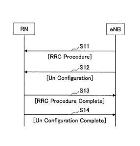
Fig. 1 shows a sequence performed between
the base station (eNB) and the relay station (RN)
when reporting given setting information to the
1
CA 02808522 2013-02-13
-6-
relay station (RN).
In step Sll, the base station (eNB)
transmits, to the relay station (RN), first setting
information common to the user apparatus (UE) and
the relay station (RN) by using an individual first
RRC message. In the figure, "RRC Procedure"
indicates that the procedure using the first RRC
message is a procedure for setting an RRC connection
such as an RRC connection reconfiguration message.
More particularly, the first setting information
includes information indicating a priority of a
radio bearer by a logical path, information
indicating usage of resources in semi-persistent
scheduling (SPS), information indicating resources
of the sounding reference signal (SRS), and
configuration information in a MAC sublayer and the
like. But, the first setting information is not
limited to these pieces of information. For example,
information on change of a security encryption key
in handover may be included in the first setting
information. Although not shown in the figure, the
relay station (RN) establishes a logical path
according to the first setting information so as to
be able to communicate with the base station (eNB)
like the user apparatus (UE).
In step S12, the base station (eNB)
transmits, to the relay station (RN), second setting
information dedicated to the relay station (RN) by
using an individual second RRC message. In the
figure, "Un Configuration" indicates that the second
setting information is related to configuration of
the relay station (RN). There is no conventional
RRC procedure corresponding to this procedure using
the second RRC message. The second setting
information includes, for example, system
information reported to the user apparatus and
information indicating a subframe for MBSFN. But,
CA 02808522 2013-02-13
-7-
the second setting information is not limited to
these pieces of information. Although not shown in
the figure, the relay station (RN) establishes a
logical path according to the second setting
information in addition to the first setting
information so as to be able to communicate with the
base station (eNB) as a relay station (RN).
In step S13, the relay station (RN)
reports, to the base station (eNB), that the relay
station (RN) has properly received the first RRC
message in step Sll by using an RRC Procedure
Complete message.
In step S14, the relay station (RN)
reports, to the base station (eNB), that the relay
station (RN) has properly received the second RRC
message in step S12 by using a Un Configuration
Complete message.
According to the procedure shown in the
figure, after the base station (eNB) transmits the
first RRC message in step Sll, the base station
(eNB) transmits the second RRC message in step S12
without waiting for reception of a response message
(RRC Procedure Complete) for the first RRC message.
Therefore, the relay station (RN) can receive the
first and the second RRC messages quickly and can
make settings as a relay station promptly.
Fig. 2 shows another sequence performed
between the base station (eNB) and the relay station
(RN) when reporting given setting information to the
relay station (RN).
In step S21, the base station (eNB)
transmits, to the relay station (RN), first setting
information common to the user apparatus (UE) and
the relay station (RN) by using an individual first
RRC message. This corresponds to the procedure of
step Sll in Fig. 1. Although not shown in the
figure, the relay station (RN) establishes a logical
CA 02808522 2013-02-13
-8-
path according to the first setting information so
as to be able to communicate with the base station
(eNB) like the user apparatus (UE).
In step S22, the relay station (RN) reports,
to the base station (eNB), that the relay station
(RN) has properly received the first RRC message in
step S21 by using an RRC Procedure Complete message.
It should be noted that the order of the sequence is
different from that shown in Fig. 1 in this point.
In step S23, the base station (eNB)
transmits, to the relay station (RN), second setting
information dedicated to the relay station (RN) by
using an individual second RRC message. This step
corresponds to the procedure of step S12 in Fig. 1.
Although not shown in the figure, the relay station
(RN) establishes a logical path according to the
second setting information in addition to the first
setting information so as to be able to communicate
with the base station (eNB) as a relay station (RN).
In step S24, the relay station (RN) reports,
to the base station (eNB), that the relay station
(RN) has properly received the second RRC message in
step S23 by using a Un Configuration Complete
message.
According to the procedure shown in Fig. 2,
after the base station (eNB) transmits the first RRC
message in step S21, the base station (eNB) receives
the response massage (RRC Procedure Complete) for
the first RRC message in step S22. After that, the
base station (eNB) transmits the second RRC message
in step S23. Therefore, the time when the relay
station (RN) can receive both of the first and the
second RRC messages is later than the case of the
sequence of Fig. 1. However, in the sequence of Fig.
2, in a case when the response signal (RRC Procedure
Complete) for the first RRC message does not arrive
at the base station (eNB), the base station (eNB)
CA 02808522 2013-02-13
-9-
can avoid wasteful transmission of the second RRC
message. This point is advantageous.
Fig. 3 shows another sequence performed
between the base station (eNB) and the relay station
(RN) when reporting given setting information to the
relay station (RN). Figs. 1 and 2 correspond to
sequences when the relay station (RN) is launched,
and Fig. 3 corresponds to a sequence while the relay
station (RN) is operating after the relay station
(RN) is launched.
In step S31, the base station (eNB)
transmits, to the relay station (RN), first setting
information common to the user apparatus (UE) and
the relay station (RN) by using an individual first
RRC message. This step corresponds to the procedure
of step Sll of Fig. 1. Although not shown in the
figure, the relay station (RN) establishes a logical
path according to the first setting information so
as to be able to communicate with the base station
(eNB) like the user apparatus (UE). After that,
procedures described with reference to Fig. 1 or Fig.
2 are performed, so that the relay station (RN)
establishes a logical path according to the second
setting information in addition to the first setting
information so as to be able to communicate with the
base station (eNB) as a relay station (RN). After
that, it is assumed that second setting information
required for the relay station (RN) to function as a
relay station (RN) is updated in the base station
(eNB).
In step S32, the base station (eNB)
transmits the updated second setting information to
the relay station (RN) by using an individual second
RRC message. The relay station (RN) establishes a
logical path according to the updated second setting
information so that the relay station (RN) is able
to communicate with the base station (eNB) as a
CA 02808522 2013-02-13
-10-
proper relay station (RN).
In step S33, the relay station (RN)
reports, to the base station (eNB), that the relay
station (RN) has properly received the second RRC
message in step S32 by using a Un Configuration
Complete message.
As mentioned above, in the case where the
second setting information is updated in the base
station (eNB), the relay station (RN) receives the
updated second setting information so that the relay
station (RN) can efficiently establish the logical
path having updated settings. If the relay station
(RN) does not perform such an updating procedure,
there is a fear that a radio link cannot be properly
maintained between the base station (eNB) having the
updated new settings and the relay station (RN)
having old settings.
As described with reference to Figs. 1-3,
first, the base station (eNB) transmits, to the
relay station (RN), the first setting information
that is common to the user apparatus (UE) and the
relay station (RN) by using the individual first RRC
message. By establishing a logical path according
to the first setting information, it becomes
possible that the relay station (RN) can communicate
with the base station (eNB) in the same way as the
user apparatus (UE).
Next, the base station (eNB) transmits, to
the relay station (RN), the second setting
information that is dedicated to the relay station
(RN) by using the individual second RRC message. By
re-establishing a logical path according to the
second setting information in addition to the first
setting information, the relay station (RN) can
communicate with the base station (eNB) as a relay
station (RN).
If the logical path is re-established
CA 02808522 2013-02-13
-11-
according to the first setting information after
establishing the logical path according to the
second setting information, there is a fear that the
relay station (RN) cannot properly operate as a
relay station (RN) since settings dedicated to the
relay station (RN) are changed to settings common to
the relay station (RN) and the user apparatus (UE).
In addition, the relay station (RN) needs to receive
a signal from the base station (eNB) by using
subframes (for example, one or more of #1, #2, #3,
#6, #7, #8) that can be configured as MBSFN in a
radio frame including 10 subframes, for example
(there is no such restriction in the user apparatus
(UE)). Therefore, if this setting is made first,
the relay station (RN) needs to receive a signal
from the base station (eNB) in limited subframes
equal to or less than 6, so that there is a fear
that the time of completion of setting is delayed.
Therefore, it is preferable to establish the logical
path according to the second setting information
dedicated to the relay station (RN) after
establishing the logical path according to the first
setting information common to the user apparatus
(UE) and the relay station (RN), and to update the
second setting information as necessary.
<2. In a case where setting fails>
<<2.1 Reconnection request for each message>>
As described with reference to Figs. 1-3,
the relay station (RN) establishes the logical path
by properly receiving the first RRC message (RRC
Procedure) and the second RRC message (Un
Configuration) so that the relay station (RN) can
function as a relay station (RN). Therefore, in a
case where both or one of the first and the second
RRC messages cannot be properly received, the relay
station (RN) cannot function as a proper relay
station (RN). In such a case, in the following
CA 02808522 2013-02-13
-12-
example, the relay station (RN) can urge the base
station (eNB) to retransmit the first and the second
RRC messages by using an RRC message for
reconnection.
Fig. 4 shows a sequence performed between
the base station (eNB) and the relay station (RN).
In step S41, the base station (eNB) transmits, to
the relay station (RN), first setting information
common to the user apparatus (UE) and the relay
station (RN) by using an individual first RRC
message. This corresponds to the procedure of step
Sll in Fig. 1. However, it is assumed that the
relay station (RN) cannot properly set the first
setting information for some reason. For example,
it can be considered that all or a part of pieces of
setting information are lost due to fading.
In step S42, the relay station (RN)
transmits an RRC message for reconnection (RRC
connection re-establishment) to the base station
(eNB). Although not shown in the figure, when the
base station (eNB) receives the RRC message for
reconnection (RRC connection re-est), the base
station (eNB) retransmits the first setting
information by using the first RRC message (RRC
Procedure).
Fig. 5 shows another sequence performed
between the base station (eNB) and the relay station
(RN). In step S51, the base station (eNB) transmits,
to the relay station (RN), first setting information
common to the user apparatus (UE) and the relay
station (RN) by using an individual first RRC
message. This corresponds to the procedure of step
Sll in Fig. 1. Although not shown in the figure,
the relay station (RN) establishes a logical path
according to the first setting information so as to
be able to communicate with the base station (eNB)
like the user apparatus (UE).
,
CA 02808522 2013-02-13
-13-
In step S52, the relay station (RN)
reports, to the base station (eNB), that the relay
station (RN) has properly received the first RRC
message in step S51 by using an RRC Procedure
Complete message.
In step S53, the base station (eNB)
transmits, to the relay station (RN), second setting
information dedicated to the relay station (RN) by
using an individual second RRC message. This
corresponds to the procedure of step S12 in Fig. 1.
However, it is assumed that the relay station (RN)
cannot properly set the second setting information
for some reason. For example, it can be considered
that all or a part of pieces of the setting
information are lost due to fading.
In step S54, the relay station (RN)
transmits an RRC message for reconnection (RRC
connection re-establishment) to the base station
(eNB). Although not shown in the figure, when the
base station (eNB) receives the RRC message for
reconnection (RRC connection re-est), the base
station (eNB) retransmits the first setting
information by using the first RRC message (RRC
Procedure). The second RRC message (Un
Configuration) in step S53 is a message that does
not exist in a conventional sequence. Thus, it
should be noted that the RRC message for
reconnection (RRC connection re-est) is also a
message that does not exist in a conventional
sequence, in which the RRC message for reconnection
is transmitted in step S54 in response to the event
that the second RRC message cannot be properly
received.
In the cases of the examples shown in Figs.
4 and 5, the RRC message for reconnection (RRC
connection re-est) is transmitted as necessary for
each of the first RRC message (RRC Procedure) and
CA 02808522 2013-02-13
-14-
the second RRC message (Un Configuration).
Therefore, the base station that receives the RRC
message for reconnection (RRC connection re-est) can
identify which one of the first and the second RRC
messages cannot be properly received. For example,
in a case where the base station (eNB) receives the
RRC message for reconnection (RRC connection re-est)
instead of the response signal (RRC Procedure
Complete) for the first RRC message, the base
station (eNB) can retransmit the first RRC message
quickly without transmitting the second RRC message
wastefully.
<<2.2 Request retransmission collectively>>
Fig. 6 shows another sequence performed
between the base station (eNB) and the relay station
(RN). In step S61, the base station (eNB) transmits,
to the relay station (RN), first setting information
common to the user apparatus (UE) and the relay
station (RN) by using an individual first RRC
message. This corresponds to the procedure of step
Sll in Fig. 1. However, it is assumed that the
relay station (RN) cannot properly set the first
setting information for some reason. For example,
it can be considered that all or a part of pieces of
setting information are lost due to fading.
In the sequence of Fig. 6, different from
the sequence of Fig. 4, in step S62, the base
station (eNB) transmits, to the relay station (RN),
the second setting information dedicated to the
relay station (RN) by using the individual second
RRC message (Un Configuration). That is, the base
station (eNB) transmits the second RRC message (Un
Configuration) to the relay station (RN),
irrespective of whether the base station (eNB)
receives the response signal (RRC Procedure
Complete) from the relay station (RN) for the first
RRC message (RRC Procedure).
CA 02808522 2013-02-13
-15-
In step S63, the relay station (RN)
transmits an RRC message for reconnection (RRC
connection re-establishment) to the base station
(eNB). Although not shown in the figure, when the
base station (eNB) receives the RRC message for
reconnection (RRC connection re-est), the base
station (eNB) retransmits the first RRC message (RRC
Procedure) and the second RRC message (Un
Configuration).
Fig. 7 shows a sequence performed between
the base station (eNB) and the relay station (RN).
The sequence is similar to the sequence of Fig. 6 in
general, but they are different in the time at which
reception fails.
In step S71, the base station (eNB)
transmits, to the relay station (RN), the first
setting information common to the user apparatus
(UE) and the relay station (RN) by using an
individual first RRC message. This corresponds to
the procedure of step Sll in Fig. 1.
In step S72, the base station (eNB)
transmits the second setting information dedicated
to the relay station (RN) by using an individual
second RRC message. That is, the base station (eNB)
transmits the second RRC message to the relay
station (RN) irrespective of whether the base
station (eNB) receives the response signal (RRC
Procedure Complete) from the relay station (RN) for
the first RRC message. However, it is assumed that
the relay station (RN) cannot properly set the
second setting information for some reason. For
example, it can be considered that all or a part of
pieces of setting information are lost due to fading.
In step S73, the relay station (RN)
transmits an RRC message for reconnection (RRC
connection re-establishment) to the base station
(eNB). Although not shown in the figure, when the
CA 02808522 2013-02-13
-16-
base station (eNB) receives the RRC message for
reconnection (RRC connection re-est), the base
station (eNB) retransmits the first RRC message (RRC
Procedure) and the second RRC message (Un
Configuration).
In the cases of the examples shown in Figs.
6 and 7, the relay station (RN) transmits the RRC
message for reconnection (RRC connection re-est)
after the second RRC message that is after the first
RRC message. Therefore, the RRC message for
reconnection (RRC connection re-est) is transmitted
only once for the two first and second RRC messages.
In this point, sequences of Figs. 6 and 7 are
different from the sequences of Figs. 4 and 5 in
which the RRC message for reconnection (RRC
connection re-est) is transmitted as necessary for
each of the first and the second RRC messages.
<<2.3 Retransmission request when updating>>
Fig. 8 shows another sequence performed
between the base station (eNB) and the relay station
(RN). Figs. 4-7 correspond to sequences when the
relay station (RN) is launched, and Fig. 8
corresponds to a sequence while the relay station
(RN) is operating after it is launched.
In step S81, the base station (eNB)
transmits, to the relay station (RN), the first
setting information common to the user apparatus
(UE) and the relay station (RN) by using an
individual first RRC message. This corresponds to
the procedure of step Sll in Fig. 1. Although not
shown in the figure, the relay station (RN)
establishes a logical path according to the first
setting information so that the relay station (RN)
can communicate with the base station (eNB) like the
user apparatus (UE). After that, procedures
described in Fig. 1 or Fig. 2 are performed, and the
relay station (RN) can communicate with the base
,
CA 02808522 2013-02-13
-17-
station (eNB) as a relay station (RN) by
establishing a logical path according to the second
setting information. After that, it is assumed that
the second setting information necessary for the
relay station (RN) to function as a relay station
(RN) is updated in the base station (eNB).
In step S82, the base station (eNB)
transmits the second setting information dedicated
to the relay station (RN) by using an individual
second RRC message. This corresponds to the
procedure of step S12 in Fig. 1. However, it is
assumed that the relay station (RN) cannot properly
set the second setting information for some reason.
For example, it can be considered that all or a part
of pieces of setting information are lost due to
fading.
In step S83, the relay station (RN)
transmits the RRC message for reconnection (RRC
connection re-establishment) to the base station
(eNB). Although not shown in the figure, when the
base station (eNB) receives the RRC message for
reconnection (RRC connection re-est), the base
station (eNB) retransmits updated second setting
information by using a second RRC message (Un
Configuration).
As described with reference to Figs. 4-8,
in a case where the relay station (RN) fails to
receive the first RRC message (RRC Procedure) and/or
the second RRC message (Un Configuration), the relay
station (RN) transmits the RRC message for
reconnection (RRC connection re-est) to the base
station (eNB). Accordingly, the base station (eNB)
can retransmit the first and the second RRC messages
to the relay station (RN).
<<2.4 Operation flow>>
Fig. 9 is a flowchart for explaining
operation described with reference to Figs. 4-8 from
[
CA 02808522 2013-02-13
-18-
the viewpoint of the relay station (RN).
In step S91, the relay station (RN)
determines whether there are existing settings of
the first RRC message (RRC Procedure) and the second
RRC message (Un Configuration). When the
determination is No, since there are no existing
settings, this operation corresponds to operation
when the relay station (RN) is launched. Thus, the
flow goes to step S92. When the determination is
Yes, since there are the existing settings, this
operation corresponds to operation when updating.
Thus, the flow goes to step S96.
In step S92, the relay station (RN)
determines whether setting by the first RRC message
(RRC Procedure) is completed. When the setting has
not been completed, the flow goes to step S93.
In step S93, due to failure of the setting,
the relay station (RN) transmits an RRC message for
reconnection (RRC connection re-est) to the base
station (eNB). This step corresponds to step S42 of
Fig. 4 and step S63 of Fig. 6. After that, the base
station (eNB) transmits, to the relay station (RN),
the first RRC message (RRC Procedure) and the second
RRC message (Un Configuration).
On the other hand, when setting of the
first RRC message (RRC Procedure) has been completed
in step S92, the flow goes to step S94.
In step S94, the relay station (RN)
determines whether setting by the second RRC message
(Un Configuration) has been completed. When the
setting has not been completed, the flow goes to
step S93, and the relay station (RN) transmits the
RRC message for reconnection (RRC connection re-est)
to the base station (eNB). This step corresponds to
step S54 of Fig. 5 and step S73 of Fig. 7. After
that, the base station (eNB) transmits, to the relay
station (RN), the first RRC message (RRC Procedure)
CA 02808522 2013-02-13
-19-
and the second RRC message (Un Configuration). On
the other hand, when the setting by the second RRC
message (Un Configuration) has been completed, the
flow goes to step S95.
In the case where the flow goes to step
S95, settings by the first RRC message (RRC
Procedure) and the second RRC message (Un
Configuration) have been properly made, so that
setting of the logical path in the relay station
(RN) completes, and the flow ends.
On the other hand, in step S91, when there
are existing settings of the first RRC message (RRC
Procedure) and the second RRC message (Un
Configuration), the flow goes to step S96.
In step S96, the relay station (RN)
determines whether setting by the second RRC message
has been completed. When the setting has not been
completed, the flow goes to step S93, and the relay
station (RN) transmits the RRC message for
reconnection (RRC connection re-est) to the base
station (eNB). After that, the base station (eNB)
transmits, to the relay station (RN), the first RRC
message (RRC Procedure) and the second RRC message
(Un Configuration). On the other hand, in step S96,
when the setting by the second RRC message (Un
Configuration) has been completed, the flow goes to
step S95. As mentioned above, this case corresponds
to operation when updating.
In the case where the flow goes to step
S95, settings by the first RRC message (RRC
Procedure) and the second RRC message (Un
Configuration) have been properly made, so that
setting of the logical path in the relay station
(RN) completes, and the flow ends.
<3. Setting items>
As mentioned above, in the case when the
relay station (RN) is launched, the relay station
CA 02808522 2013-02-13
-20-
(RN) receives the first RRC message (RRC Procedure)
and the second RRC message (Un Configuration) to
make settings, and when updating, the relay station
(RN) receives the second RRC message (Un
Configuration) to make settings. Therefore, in
order that such operation can be realized, it is
necessary to properly set the first setting
information included in the first RRC message (RRC
Procedure) and the second setting message included
in the second RRC message (Un Configuration).
The first setting information is
information common to the user apparatus (UE) and
the relay station (RN). More particularly, the
first setting information includes information
indicating priority of a radio bearer by a logical
path, information indicating usage of resources in
semi-persistent scheduling (SPS), information
indicating resources of a sounding reference signal
(SRS), and configuration information in MAC sublayer,
and the like. But the first setting information is
not limited to these pieces of information. For
example, information on change of a security
encryption key by handover may be included in the
first setting information.
The second setting information is
information dedicated to the relay station (RN).
More specifically, the second setting information
includes system information reported to the user
apparatus, and information indicating a subframe for
MBSFN. System information is information
transmitted by a master information block (MIB) and
a system information block (SIB). The system
information includes, for example, the minimum
information such as system bandwidth and system
frame number, information indicating cell ID, cell
selection information, tracking area and the like,
scheduling information for information after SIB2,
i
CA 02808522 2013-02-13
-21-
configuration information of radio resources common
to all user apparatuses (UE), information common to
cell reselection of the same frequency and different
frequency, information on cell reselection of the
same frequency, information on cell reselection of
different frequency and different RAT, and the like.
But, the system information is not limited to these
pieces of information.
Fig. 10 shows a sequence performed between
the base station (eNB) and the relay station (RN).
Although the sequence is the same as the sequence
described with reference to Fig. 2, other sequences
such as ones shown in Figs. 1 and 3 and the like may
be used.
In step S101, the base station (eNB)
transmits, to the relay station (RN), the first
setting information common to the user apparatus
(UE) and the relay station (RN) by using the
individual first RRC message (RRC Procedure). The
first setting information is stored in a setting
database for user apparatus (setting DB for UE) of
the base station (eNB). In the example shown in the
figure, there are 26 items, in total, that are
settable in the user apparatus (UE) and the relay
station (RN). In the items, there are 20 items for
the first setting information, the 20 items being
represented as A, B, ...T for the sake of
convenience. The value of the setting item A is 1,
the value of the setting item B is 2, values are set
in this manner for the following items, and the
value of the setting item T is 20. The number of
the setting items and the values are merely shown as
examples for the sake of convenience of explanation,
and any proper values may be used. The relay
station (RN) sets the values of the setting items A-
T according to the first setting information, so
that the relay station (RN) can communicate with the
1
CA 02808522 2013-02-13
-22-
base station (eNB) like the user apparatus (UE).
In step S102, the relay station (RN)
reports, to the base station (eNB), that the relay
station (RN) has properly received a first RRC
message in step S101 by using an RRC Procedure
Complete message. The report of the RRC Procedure
Complete message may be performed at later timing.
In step S103, the base station (eNB)
transmits, to the relay station (RN), the second
setting information dedicated to the relay station
(RN) by using an individual second RRC message. The
second setting information is stored in a setting
database for relay station (setting DB for RN) in
the base station (eNB). The setting DB for UE and
the setting DB for RN may be provided separately, or
the setting DB for UE and the setting DB for RN may
be provided by dividing one database. The relay
station (RN) sets the values of the setting item A
and the setting items U-Z according to the second
setting information, so as to be able to communicate
with the base station (eNB) as a relay station (RN).
The setting item A is included in both of the first
setting information and the second setting
information. But, they are different in that the
value is 1 in the first setting information and the
value is 30 in the second setting information. In
this case, setting (the value of setting item A in
the second setting information) as the relay station
(RN) is prioritized, so that the value of the
setting item A is changed (overwritten) from 1 to 30.
The setting items U-Z are not included in the first
setting information for the user apparatus (UE), but
are included in the second setting information for
the relay station (RN). As to such items that
correspond to differences of setting items, settings
are added in the relay station (RN), and, as to an
overlapping setting item, the value for the relay
CA 02808522 2013-02-13
-23-
station (RN) is overwritten.
Information corresponding to the setting
items A-T is information common to the user
apparatus (UE) and the relay station (RN). More
particularly, the information includes information
indicating priority of radio bearer by a logical
path, information indicating usage of resources in
semi-persistent scheduling (SPS), information
indicating resources of a sounding reference signal
(SRS), and configuration information in MAC sublayer,
and the like. But the information is not limited to
these pieces of information. For example,
information on change of security encryption key by
handover may be included in the information.
Processing for overwriting a setting item is
performed not only when launching but also when
updating the setting item as a matter of course.
Information corresponding to the setting
items U-Z is information dedicated to the relay
station (RN). More specifically, the information is
system information reported to the user apparatus
and information indicating a subframe for MBSFN, and
the like.
In step S104, the relay station (RN)
reports, to the base station (eNB), that the relay
station (RN) has properly received the second RRC
message (Un Configuration) in step S103 by using a
Un Configuration Complete message.
As mentioned above, setting items common
to the user apparatus (UE) and the relay station
(RN) are reported to the relay station (RN) by the
first RRC message (RRC Procedure), and the setting
items dedicated to the relay station (RN) are
reported to the relay station (RN) by the second RRC
message (Un Configuration). By reporting the
various setting items separately in this way, it is
only necessary to report only the second RRC message
CA 02808522 2013-02-13
-24-
(Un Configuration) to the relay station (RN) in the
case when changing settings of the relay station
(RN) after step S104. Accordingly, the sequence
described with reference to Fig. 3 can be realized.
<4. Base station (eNB) and relay station (RN)>
Fig. 11 shows a functional block diagram
of the base station (eNB) and the relay station (RN).
As to functional elements shown in the figure,
functional elements necessary for above-mentioned
various operations are shown in various functional
elements included in the base station (eNB) and the
relay station.
The base station (eNB) which is a donor
base station (DeNB) includes, at least, an RRC
setting item separating unit 111, a transmission
order control unit 112, a setting information
transmission unit 113, and a reconnection control
unit 114. The relay station (RN) includes, at least,
a setting information receiving unit 115, an
overwriting determination unit 116, a setting
reflection unit 117, and a reconnection necessity
determination unit 118.
In the RRC setting item separation unit
111, the base station (eNB) identifies the first
setting information (setting items A-T in Fig. 10)
common to the user apparatus (UE) and the relay
station (RN), and second setting information
(setting items A, U-Z) dedicated to the relay
station (RN), and outputs the first and the second
setting information. The transmission order control
unit 112 controls transmission order such that the
second RRC message (Un Configuration) including the
second setting information is transmitted after the
first RRC message (RRC Procedure) including the
first setting information. The setting information
transmission unit 113 transmits, to the relay
station (RN), the second RRC message (Un
CA 02808522 2013-02-13
-25-
Configuration) including the second setting
information after the first RRC message (RRC .
Procedure) including the first setting information,
according to an instruction from the transmission
order control unit 112.
In the relay station (RN), the setting
information receiving unit 115 receives the second
RRC message (Un Configuration) including the second
setting information after receiving the first RRC
message (RRC Procedure) including the first setting
information. The overwriting determination unit 116
determines necessity of overwriting already-set
setting items. The overwriting determination unit
116 is not only used in the case when determining
whether to overwrite the setting item A in step S103
of Fig. 10 but also used in the case when
determining whether to update a value in updating.
The setting reflection unit 117 sets a value of each
setting item.
On the other hand, the relay station (RN)
determines, by the reconnection necessity
determination unit 118, determines whether setting
information is properly obtained from the received
first and the second RRC messages. When the setting
information is not properly obtained, the relay
station (RN) transmits an RRC message (RRC
connection re-est) for requesting reconnection to
the base station (eNB). The base station (eNB)
processes, by the reconnection control unit 114, the
RRC message (RRC connection re-est) for requesting
reconnection and sends an instruction to the setting
information transmission unit 113 so as to
retransmit the first and the second RRC messages.
In the above, the present invention has
been explained while referring to the specific
embodiments. However, these are merely exemplary.
Those skilled in the art will conceive of various
CA 02808522 2013-02-13
-26-
modified examples, corrected examples, alternative
examples, substituted examples, and the like.
Classification into each embodiment or item in the
description is not essential in the present
invention, and features described in two or more
items may be combined and used as necessary.
Subject matter described in an item may be applied
to subject matter described in another item
(provided that they do not contradict).
For example, when performing the processes
shown in Fig. 1 in which the second RRC message (Un
Configuration) is reported to the relay station (RN)
after the first RRC message (RRC Procedure), the
processes shown in Figs. 6 and 7 may be used
together in which the relay station (RN) transmits
the RRC message for reconnection (RRC connection re-
est) as necessary. In addition, dividing setting
items and prioritizing setting items of the relay
station (RN) described with reference to Fig. 10 may
be performed when performing the processes shown in
Fig. 1. Similarly, the processes shown in Figs. 4
and 5 may be performed when performing the processes
shown in Fig. 2. Further, dividing setting items
and prioritizing setting items of the relay station
(RN) may be performed when performing the processes
shown in Fig. 2. Also, the processes shown in Fig.
3 and 5 may be performed when performing the
processes shown in Fig. 8. Further, dividing
setting items and prioritizing setting items of the
relay station (RN) may be performed when performing
the processes shown in Fig. 3.
The present invention may be applied to
any suitable mobile communication system using a
relay station that relays communication between a
base station and a user apparatus. For example, the
present invention may be applied to systems of W-
CDMA scheme, W-CDMA systems of the HSDPA/HSUPA
CA 02808522 2013-02-13
-27-
scheme, systems of the LTE scheme, systems of the
LTE-Advanced scheme, systems of the TNT-Advanced
scheme, WiMAX, Wi-Fi scheme systems and the like.
While specific numerical value examples are used to
facilitate understanding of the present invention,
such numerical values are merely examples, and any
appropriate value may be used unless specified
otherwise. For convenience of explanation, the
apparatus according to the embodiment of the present
invention has been explained by using a functional
block diagram. However, the apparatus may be
implemented in hardware, software, or a combination
thereof. The software may be stored in any proper
storage medium such as a RAM (Random Access Memory),
a flash memory, a ROM (Read Only Memory), an
EPROM(Erasable Programmable ROM), an
EEPROM(Electronically Erasable and Programmable ROM),
a register, a hard disk (HDD), a removable disk, a
CD-ROM, database, server and the like.
Therefore, the present invention is not
limited to the above-mentioned embodiment and is
intended to include various variations,
modifications, alterations, substitutions and so on
without departing from the spirit of the present
invention.
In the following, measures taught by the
present invention are listed as examples.
(eNB1)
A base station in a mobile communication
system, including:
a generation unit configured to generate
first setting information commonly used for
establishing a logical path for communication with a
user apparatus and for establishing a logical path
for communication with a relay station, and second
setting information used only for establishing the
logical path for communication with the relay
CA 02808522 2013-02-13
-28-
station; and
a transmission unit configured to transmit
an individual second RRC message including the
second setting information to the relay station
after transmitting an individual first RRC message
including the first setting information to the relay
station.
(eNB2)
The base station as described in eNB1,
wherein, after the transmission unit transmits the
first RRC message to the relay station, the
transmission unit transmits the second RRC message
to the relay station irrespective of whether the
base station receives a response signal for the
first RRC message.
(eNB3)
The base station as described in eNB1,
wherein, after the transmission unit transmits the
first RRC message to the relay station and the base
station receives a response signal for the first RRC
message, the transmission unit transmits the second
RRC message to the relay station.
(eNB4)
The base station as described in any one
of eNB1-eNB3, wherein, after the transmission unit
transmits the first RRC message to the relay station,
the base station updates settings of the logical
path by the second setting information by
transmitting the second RRC message to the relay
station repetitively.
(eNB5)
The base station as described in any one
of eNB1-eNB4, wherein, in a case where the relay
station fails to receive the first setting
information and/or the second setting information,
the base station receives an RRC message for
reconnection from the relay station, and transmits
CA 02808522 2013-02-13
-29-
the first and the second RRC message to the relay
station.
(eNB6)
The base station as described in eNB5,
wherein, in a case where the relay station fails to
receive the first setting information, the base
station receives an RRC message for reconnection
from the relay station, and, in a case where the
relay station fails to receive the second setting
information, the base station receives the RRC
message for reconnection from the relay station.
(RN1)
A relay station that communicates with a
user apparatus and a base station, including:
a receiving unit configured to receive,
from the base station, an individual second RRC
message that includes second setting information
used only for establishing a logical path for
communication with the base station after receiving,
from the base station, an individual first RRC
message that includes first setting information
commonly used for establishing a logical path for
communication with the user apparatus and for
establishing a logical path for communication with
the base station, and
a setting unit configured to establish the
logical path for communication with the user
apparatus and the logical path for communication
with the base station according to the first setting
information and to establish the logical path for
communication with the base station according to the
second setting information.
(RN 2)
The relay station as described in RN1,
wherein, the receiving unit receives the first RRC
message from the base station, and, before the relay
station transmits a response signal for the first
1
CA 02808522 2013-02-13
-30-
RRC message to the base station, the receiving unit
receives the second RRC message from the base
station.
(RN 3)
5 The relay station as described in RN1,
wherein, after the receiving unit receives the first
RRC message from the base station and the relay
station transmits a response signal for the first
RRC message to the base station, the receiving unit
receives the second RRC message from the base
station.
(RN 4)
The relay station as described in any one
of RN1-RN3, wherein, after the receiving unit
receives the first RRC message from the base station,
the relay station updates setting of the logical
path by the second setting information by receiving
the second RRC message from the base station
repetitively.
20 (RN5)
The relay station as described in any one
of RN1-RN4, wherein, in a case where the relay
station fails to receive the first setting
information and/or the second setting information,
the relay station transmits an RRC message for
reconnection to the base station, and receives the
first and the second RRC message from the base
station.
(RN 6)
30 The relay station as described in RN5,
wherein, in a case where the relay station fails to
receive the first setting information, the relay
station transmits an RRC message for reconnection to
the base station, and, in a case where the relay
station fails to receive the second setting
information, the relay station transmits the RRC
message for reconnection to the base station.
CA 02808522 2013-02-13
-31-
(Method 1)
A method in a mobile communication system,
including the steps of:
generating, in a base station, first
setting information commonly used for establishing a
logical path for communication with a user apparatus
and for establishing a logical path for
communication with a relay station, and second
setting information used only for establishing a
logical path for communication with the relay
station; and
transmitting, from the base station, an
individual second RRC message including the second
setting information to the relay station after
transmitting, from the base station, an individual
first RRC message including the first setting
information to the relay station.
(eNB1)
A base station in a mobile communication
system, including:
a generation unit configured to generate
first setting information commonly used for
establishing a logical path for communication with a
user apparatus and for establishing a logical path
for communication with a relay station, and second
setting information used only for establishing the
logical path for communication with the relay
station; and
a transmission unit configured to transmit
an individual second RRC message including the
second setting information to the relay station
after transmitting an individual first RRC message
including the first setting information to the relay
station,
wherein the first setting information
includes at least information indicating a priority
of a radio bearer in the logical path, information
CA 02808522 2013-02-13
-32-
indicating usage of resources in semi-persistent
scheduling, information indicating resources of a
sounding reference signal, configuration information
in a MAC sublayer, and information on change of a
security encryption key in handover, and
the second setting information includes at
least system information reported to the user
apparatus and information indicating a subframe for
MBSFN.
(eNB2)
The base station as described in eNB1,
wherein, in a case where there is information of a
setting item that is included in both of the first
and the second setting information in which values
of the setting item are different, a value in the
second setting information is prioritized in the
relay station.
(RN1)
A relay station that communicates with a
user apparatus and a base station, including:
a receiving unit configured to receive,
from the base station, an individual second RRC
message that includes second setting information
used only for establishing a logical path for
communication with the base station after receiving,
from the base station, an individual first RRC
message that includes first setting information
commonly used for establishing a logical path for
communication with the user apparatus and for
establishing a logical path for communication with
the base station, and
a setting unit configured to establish the
logical path for communication with the user
apparatus and the logical path for communication
with the base station according to the first setting
information and to establish the logical path for
communication with the base station according to the
1
CA 02808522 2013-02-13
-33-
second setting information,
wherein the first setting information
includes at least information indicating a priority
of a radio bearer in the logical path, information
indicating usage of resources in semi-persistent
scheduling, information indicating resources of a
sounding reference signal, configuration information
in a MAC sublayer, and information on change of a
security encryption key in handover, and
the second setting information includes at
least system information reported to the user
apparatus and information indicating a subframe for
MBSFN.
(RN 2)
The relay station as described in RN1,
wherein, in a case where there is information of a
setting item that is included in both of the first
and the second setting information in which values
of the setting item are different, a value in the
second setting information is prioritized in the
relay station.
(Methodl)
A method in a mobile communication system,
including the steps of:
generating, in a base station, first
setting information commonly used for establishing a
logical path for communication with a user apparatus
and for establishing a logical path for
communication with a relay station, and second
setting information used only for establishing a
logical path for communication with the relay
station; and
transmitting, from the base station, an
individual second RRC message including the second
setting information to the relay station after
transmitting, from the base station, an individual
first RRC message including the first setting
CA 02808522 2014-12-16
=
-34-
information to the relay station,
wherein the first setting information
includes at least information indicating a priority
of a radio bearer in the logical path, information
indicating usage of resources in semi-persistent
scheduling, information indicating resources of a
sounding reference signal, configuration information
in a MAC sublayer, and information on change of a
security encryption key in handover, and
the second setting information includes at
least system information reported to the user
apparatus and information indicating a subframe for
MBSFN.