Note: Descriptions are shown in the official language in which they were submitted.
WO 2012/027097 CA 02808616 2013-02-15PCT/US2011/047020
METHODS OF PREPARING A CROSSLIKED FIBER MEMBRANE
BACKGROUND
1. Technical Field
[0001] The present invention generally relates to methods for preparing
crosslinked fiber
membranes and their use in separating components of a gaseous mixture.
2. Description of the Related Art
[0002] Polymeric membranes for separating mixtures of gases, such as methane
and
carbon dioxide are known. For example, U.S. Pat. Nos. 7,247,191; 6,932,859;
and 6,755,900,
disclose crosslinkable polymers and crosslinked hollow fiber membranes made
from such
crosslinkable polymers. These patents further disclose a crosslinkable
polyimide polymer. The
crosslinkable polyimide polymer can be made by monoesterifying a polyimide
polymer with a
crosslinking agent.
[0003] A crosslinked hollow fiber membrane can be made by forming fibers from
the
crosslinkable polyimide polymer and transesterifying the crosslinkable
polyimide polymer
within the fibers. More specifically, the crosslinkable polyimide polymer can
be formed into
crosslinkable fibers, which are then subjected to transesterification
conditions in order to create
covalent ester crosslinks within the fibers. Such fibers can be hollow fibers
or other types of
fibers. Crosslinked hollow fiber membranes can be incorporated into a
separation module. Other
types of membranes for separation include flat sheet separation membranes or
flat stack
permeators.
[0004] Integrally skinned hollow fiber membranes can be formed by contacting
the
polymer solution with a non-solvent and forming the membrane in a one step
process. On
contact with the non-solvent, mass transfer takes place between the non-
solvent from the
1
WO 2012/027097 CA 02808616 2013-02-15 PCT/US2011/047020
coagulation bath and the solvent in the nascent membrane resulting in micro-
phase separation
within the membrane. Depending on the pathway of phase separation, a dense
layer, also called
the skin layer, is believed to form on the surface of the membrane. The skin
formation is
hypothesized to occur when solvent outflow from the membrane exceeds the non-
solvent inflow
resulting in delayed demixing. This process increases the concentration of the
polymer at the
membrane¨coagulant interface and forms the skin. An evaporative step in the
air gap can be
included prior to the phase separation step to enhance skin formation by the
evaporation of the
volatile solvent from the nascent membrane followed by a rapid phase
separation of the
underlying region to form a highly porous support.
[0005] Polymer solutions used in hollow fiber membrane spinning consist of
polymer,
solvents, non-solvent and additives. When the number of components exceeds
three, a pseudo-
ternary phase diagram of more than three components can be devised by dividing
the
components into categories of polymer, solvent and non-solvent. Within each
category, the
components can be fixed in ratio to each other to restrict solvency and/or non-
solvency power.
This approach based on fixed ratios enables holding solvency parameters
constant for the
solvents and nonsolvents that can be explored in the system and a binodal (set
of concentrations
separating the single phase and two phase regions) obtained.
[0006] While not wishing to be bound by any particular theory, ternary phase
diagrams
can be developed (1) by the titration of the polymer solution with non-
solvent, (2) through the
use of the three-phase Flory-Huggins theory for polymer solutions, and (3) by
inspection of
polymer solutions of various compositions of polymer/solvent/nonsolvent.
Depending on the
polymer viscosity in solution, the dope compositions are made to cover the
region of interest for
fiber spinning (usually 20 to 40 wt. % polymer). The binodal curve can be
generated by making
2
WO 2012/027097 CA 02808616 2013-02-15PCT/US2011/047020
small samples (10 to 15 gram) of various compositions and visually inspecting
them for phase
separation.
[0007] Once the binodal has been identified, three factors taken into
consideration when
determining the dope formulation are: (1) proximity of the dope composition to
the binodal, (2)
osmotic pressure of the solution, and (3) polymer solution viscosity.
[0008] The proximity of the polymer solution composition to the binodal and
osmotic
pressure of the solution determine the kinetics of membrane formation and
membrane
morphology. Osmotic pressure has earlier been suggested as the cause for the
large finger/tear
shaped voids (macrovoids) found in certain membranes. To describe the phase
separation of the
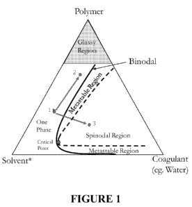
polymer solution (in forming the membrane), a ternary diagram can be formed
which groups all
the solvents, nonsolvents and additives into the solvent category, and depicts
the coagulant
(typically water) in the nonsolvent category. Based on the proximity of the
polymer solution to
the binodal, the quantity of coagulant required to phase separate the polymer
solution can be
determined. Since the penetration of the coagulant into the polymer solution
is limited by the
rate of diffusion, the distance of the polymer solution from the binodal and
the osmotic pressure
driving force determines the rate and type of phase separation. Compositional
change on the
ternary phase diagram (Figure 1) from point 1 (original polymer solution) to
point 2 is
hypothesized for the skin and from point 1 to an arbitrary position 3 (in the
spinodal region) for
the support layer of the membrane. The objective is to drive phase separation
of the support layer
through spinodal decomposition mechanism to form a highly porous support with
little or no
resistance to gas flow.
[0009] The minimum polymer solution viscosity depends on the strength of the
polymer
solution strand which undergoes elongation (under gravity) that takes place
after the fiber exits
3
WO 2012/027097 CA 02808616 2013-02-15 PCT/US2011/047020
the spinneret. Based on the air gap and draw ratio, this minimum viscosity
must be defined for
each polymer/solvent/nonsolvent system. A higher viscosity can be achieved by
increasing the
polymer concentration in the polymer solution or by adding viscosity
enhancers, like lithium
nitrate (LiNO3) and carboxylic acids which complex with the common spinning
solvents (i.e. N-
methyl-2-pyrrolidone). Although a high polymer concentration is generally
required to promote
skin growth and increase viscosity for spinning, it is believed that too high
of a polymer
concentration would reduce porosity in the support layer and form a support
layer with
substantial resistance to gas flow which is undesirable.
[0010] Solvents and non-solvents are selected, in part, for their
miscibility with the
aqueous coagulant. Another factor for consideration in the selection of the
polymer solution
solvent is the generation of osmotic pressure during phase separation. The
osmotic pressure is a
function of the thermodynamic activities of the solvent and coagulant non-
solvent, and is
believed to be a factor in the formation of macrovoids.
[0011] The crosslinked hollow fiber membranes have good permeability and
selectivity.
The crosslinked hollow fiber membranes also have good resistance to
plasticization.
Plasticization occurs when one or more components of a fluid mixture causes
the polymer to
swell thereby altering the properties of the membrane. For example, polyimides
are particularly
susceptible to plasticization by carbon dioxide. Subjecting the fibers to
transesterification
conditions to crosslink the crosslinkable polyimide polymer within the fibers
increases both
resistance to plasticization and selectivity.
[0012] The above referenced patents disclose the use of sufficiently high
molecular
weight polyimide polymers to accommodate for molecular weight loss during the
monoesterification process. However, it is difficult to produce crosslinkable
polyimide polymers
4
WO 2012/027097 CA 02808616 2013-02-15PCT/US2011/047020
having such a high molecular weight. Therefore, there is a need for a method
of making a
crosslinkable (i.e., monoesterified) polyimide polymer that reduces or
eliminates the loss of
molecular weight during the monoesterification process, i.e., a high molecular
weight,
monoesterified polyimide polymer, while having improved strength, flexibility,
and/or
spinnability.
SUMMARY
[0013] In accordance with one embodiment, there is provided a method for
preparing a
crosslinked hollow fiber membrane, which comprises spinning a one phase
solution comprising a
monoesterified polyimide polymer, acetone as a volatile solvent, a spinning
solvent, and a
spinning non-solvent, wherein the volatile solvent is present in an amount of
greater than 25 wt.
% to about 50 wt. %, based on the total weight of the solution.
[0014] In accordance with a second embodiment, there is provided a method for
preparing a crosslinked hollow fiber membrane, which comprises spinning a one
phase solution
comprising a monoesterified polyimide polymer, acetone as a volatile solvent,
a spinning
solvent, and a spinning non-solvent, wherein the volatile solvent is present
in an amount of
greater than 25 wt. % to about 50 wt. %, based on the total weight of the
solution, and subjecting
the monoesterified polyimide polymer fiber to transesterification conditions
to form a
crosslinked polyimide hollow fiber membrane.
[0015] In accordance with a third embodiment, there is provided a method for
preparing
a crosslinked hollow fiber membrane, which comprises spinning a one phase
solution comprising
a monoesterified polyimide polymer, a volatile solvent having a threshold
limit value time-
weighted average (TLV-TWA) toxicity of greater than 200 parts per million
(ppm) exposure
5
WO 2012/027097 CA 02808616 2013-02-15 PCT/US2011/047020
limit, a spinning solvent, and a spinning non-solvent, wherein the volatile
solvent is present in an
amount of greater than 25 wt. % to about 50 wt. %, based on the total weight
of the solution.
[0016] The use of a relatively high concentration of acetone in the polymer
solution in
place of tetrahydrofuran (THF) advantageously obtains a sufficient quantity of
evaporative
solvent (e.g., acetone) while also maintaining a single phase polymer
solution. Acetone has less
stringent storage requirements compared to THF, which can form explosive
peroxides. In
addition, while not wishing to be bound by theory, it is believed that the use
of a relatively high
concentration of acetone in the polymer solution aids in the skin formation of
the membrane in
the air gap resulting in less skin defects. It is further believed that the
use of a relatively high
concentration of acetone in the polymer solution aids in limiting the skin
formation in the
coagulant bath during membrane production and hastening phase separation to
form a more
porous support with a minimal transition layer and relatively defect free skin
in the membrane.
BRIEF DESCRIPTION OF THE DRAWINGS
[0017] FIG. 1 shows the compositional change on a ternary phase diagram.
[0018] FIG. 2 shows both a monesterification reaction and a
transesterification reaction.
[0019] FIG. 3 is a schematic representation of an asymmetric bilayer and a
graded
density skin asymmetric trilayer.
DETAILED DESCRIPTION
[0020] The present invention is directed to methods for preparing an
integrally skinned,
gas permeable asymmetric crosslinked hollow fiber. In general, the methods
involve at least
spinning a one phase solution comprising a monoesterified polyimide polymer,
acetone as a
6
WO 2012/027097 CA 02808616 2013-02-15
PCT/US2011/047020
volatile solvent, a spinning solvent, a spinning non-solvent, and optionally
an organic or
inorganic additive, wherein the volatile solvent is present in an amount of
greater than 25 wt. %
to about 50 wt. %, based on the total weight of the solution.
[0021] DEFINITIONS
[0022] The following terms are used throughout the specification
and have the following
meanings unless otherwise indicated.
[0023] As used herein, the term "carboxylic acid functional group"
refers to a pendant
group of -COOH-.
[0024] The term "diol" refers to a chemical compound containing
two hydroxyl groups.
[0025] The term "carbodiimide" means a chemical compound
containing the functional
group N=C=N.
[0026] The term "dianhydride" refers to any compound that contains
two anhydride
7 0 0 \
¨C-0¨C¨ 11 11
\ / groups.
[0027] The term "halogenated alkyl" means a straight-chain or
branched saturated
monovalent hydrocarbon group of one to twelve carbon atoms, wherein at least
one of the carbon
atoms is replaced by a halogen atom (e.g. fluoromethyl, 1-bromo-ethyl, 2-
chloro-pentyl, 6-iodo-
hexyl, and the like).
[0028] The term "halo" or "halogenated" refers to a functional
group including a halogen
atom such as fluorine, chlorine, bromine, or iodine.
[0029] The term "phenyl" means an aromatic group of six carbon
atoms having the
formula ¨C6H5.
7
WO 2012/027097 CA 02808616 2013-02-15PCT/US2011/047020
[0030] The term "alkyl" means a straight-chain or branched saturated
monovalent
hydrocarbon group of one to twelve carbon atoms (e.g. methyl, ethyl, i-propyl,
and the like).
Alkyl groups have the formula Cii1-12 1 where n is a positive non-zero
integer.
[0031] The term "diamino cyclic compound" means a chemical compound having a
ring
structure of three to twelve carbon atoms where the ring structure is
functionalized by two amino
or substituted amino groups.
[0032] The term "amino" means a functional group having the formula -NR'R"
where R'
and R" are independently H, alkyl, cycloalkyl, and aryl.
[0033] The term "cycloalkyl" means a cyclic saturated monovalent hydrocarbon
group
containing 3 to 12 carbon atoms having a single cyclic ring or multiple
condensed rings. Such
cycloalkyl groups include, by way of example, cyclopropyl, cyclohexyl,
cyclooctyl,
adamantanyl, and the like.
[0034] The term "aliphatic" refers to non-aromatic organic compounds, in
which carbon
atoms are joined together in straight or branched chains. Aliphatic includes
paraffinic (e.g.,
alkyl), olefinic (e.g., alkenyl), and alkynyl compounds.
[0035] The term "antilyotropic salt" refers to a salt that interacts with
solvent molecules
rather than polymer molecules.
[0036] The term "amide" means a functional group having a carbonyl group
(C=0)
linked to a nitrogen atom or a compound that includes this functional group.
[0037] The term "ester" means a functional group having a carbonyl group
(C=0) linked
to an alkoxy group.
[0038] The term "alkoxy" refers to an alkyl group linked to an oxygen atom
such as, for
example, methoxy or ethoxy.
8
WO 2012/027097 CA 02808616 2013-02-15 PCT/US2011/047020
[0039] The term "aryl" refers to an unsaturated aromatic carbocyclic group
of from 6 to
20 carbon atoms having a single ring (e.g., phenyl) or multiple condensed
(fused) rings (e.g.,
naphthyl or anthryl). Exemplary aryls include phenyl, naphthyl and the like.
[0040] The term "alkenyl" refers to a linear or branched unsaturated
monovalent
hydrocarbon group having 2 to 12 carbon atoms and containing at least one, for
example, from 1
to 3 double bond(s). This term is exemplified by groups such as ethenyl, 2-
propenyl, and the
like.
[0041] The term "alkynyl" refers to a linear or branched monovalent
hydrocarbon group
having 2 to 12 carbon atoms and containing at least one, for example, from 1
to 3 triple bond(s).
This term is exemplified by groups such as ethynyl, 2-propynyl, n-butynyl and
the like.
[0042] As used herein, the term "reduce" means to decrease or diminish.
[0043] Whenever used herein, the term "molecular weight" or "average
molecular
weight" means weight average molecular weight as measured by Gel Permeation
Chromatography (GPC) using polystyrene as the standard. This method is
described in ASTM
D5296-05.
[0044] "Draw ratio" refers to the ratio of the take-up rate of an extruded
fiber to the
extrusion rate of the fiber.
[0045] I. Method of Making Monoesterified Polyimide Polymer
[0046] The monoesterified polyimide polymer can be obtained by (a) preparing
a
polyimide polymer comprising carboxylic acid functional groups from a reaction
solution
comprising monomers and at least one solvent; and (b) treating the polyimide
polymer with a
diol at esterification conditions in the presence of dehydratingconditions to
form a
9
CA 02808616 2013-02-15
WO 2012/027097
PCT/US2011/047020
monoesterified polyimide polymer, wherein the dehydrating conditions at least
partially remove
water produced during steps (a) and (b).
[0047] Step (a)-Polymerization Reaction and Imidization Reaction
[0048] In step (a), monomers are polymerized to form a polyamide
polymer comprising
amide bonds. Next, in step (a), an imidization reaction occurs wherein the
amide bonds of the
polyamide polymer form imide bonds transforming the polyamide polymer into a
polyimide
polymer and product water is removed. The resultant polyimide polymer includes
carboxylic
acid functional groups which are capable of crosslinking chains of the
polyimide polymer.
[0049] Monomers
[0050] The monomers can comprise between about 15 and about 25 weight
percent of
the reaction solution.
[0051] At least some of the monomers include carboxylic acid
functional groups such
that the resultant polyimide polymer comprises carboxylic acid functional
groups. The
monomers can include dianhydrides, tetracarboxylic acids, and furandiones. The
monomers can
further include diamino compounds such as diamino cyclic compounds and diamino
aromatics.
The diamino aromatics can have more than one aromatic ring where the amino
groups are on the
same or different aromatic ring.
[0052] For example, the monomers can include monomers A, B, and C
wherein
[0053] A is a dianhydride of formula (I):
0 R1 X1 x2-4 0
0)1.-----o 0 R2 R5
0 R3 R6 0(I)
10
CA 02808616 2013-02-15
WO 2012/027097 PCT/US2011/047020
[0054] X1 and X2 are independently selected from halogenated alkyl, phenyl or
halogen;
[0055] R1, R2, R3, R4, R5, and R6 are H, alkyl, or halogen;
[0056] B is a diamino cyclic compound without a carboxylic acid functionality;
and
[0057] C is a diamino cyclic compound with a carboxylic acid functionality.
[0058] If the monomers are comprised of the monomers A, B, and C, the ratio of
B to C
can be between 1:4 and 8:1.
[0059] The monomer A can be 4,4'-(hexafluoroisopropylidene) diphthalic
anhydride
(6FDA), which is also known as (2,2-bis(3,4-dicarboxyphenyl)
hexafluoropropane. 6FDA has
the following formula:
0 CF3 CF3 0
0)1.----
y, o 0
0 0
[0060] Including 6FDA in the monomers provides stability to the polyimide
polymer
because 6FDA has limited rotational ability.
[0061] Monomers with limited rotational ability, like 6FDA, are desirable
because they
increase the selectivity of the membrane made according to the methods
disclosed herein.
Monomers with bulky side groups, like (CF3)2 in 6 FDA, also inhibit chain
packing, which
increases permeability of molecules through the membrane. Both selectivity and
permeability
are important for efficient and productive separations. Further reference to
these structure
property relationships can be found in Koros and Fleming, Journal of Membrane
Science, 83, 1-
80 (1993).
11
CA 02808616 2013-02-15
WO 2012/027097 PCT/US2011/047020
[0062] The monomer B, a diamino cyclic compound without a carboxylic acid
functionality, can be a diamino aromatic compound with more than one aromatic
ring where the
amino groups are on the same or different aromatic rings. For example, the
monomer B can be
4,4' isopropylidene dianiline, 3,3' hexafluoroisopropylidene dianiline,
4,4'
hexafluoroisopropyliene dianiline, 4,4' oxydianiline, 3,3' oxydianiline, 4,4'
diaminodiphenyl,
diaminotoluene, diaminobenzotrifluoride, dimethyldiaminobenzene,
trimethyldiaminobenezene,
or tetramethyldiaminobenzene. The monomer B can also be 2,4,6-trimethyl-m-
phenylenediamine (DAM), which is represented by the following formula:
CH3
NH2 0 NH2
CH3
CH3
[0063] The monomer C, a diamino cyclic compound with a carboxylic acid
functionality,
can be diamino benzoic acid. It is represented by the following formula:
H2N NH2
0
C --
/ ---- 0
/
OH
[0064] More specifically, the monomer C can be 3,5 diaminobenzoic acid
(DABA).
[0065] In one embodiment of the methods as described herein, the monomers
include A,
B, and C where A is 6FDA, B is DAM, and C is DABA. In this embodiment, the
6FDA content
of the monomer mixture is about 50 percent and the remaining about 50 percent
of the monomer
mixture is composed of DAM and DABA. The DABA content is between about 20
percent and
12
WO 2012/027097 CA 02808616 2013-02-15 PCT/US2011/047020
about 100 percent of the remaining about 50 weight percent. For example, the
6FDA content of
the monomer mixture can be about 50 percent and the remaining about 50 percent
can be about
40 percent DABA and about 60 percent DAM. When 6FDA, DAM, and DABA are present
in
these stoichiometric concentrations, the polyimide polymer formed in step (a)
is represented by
the formula (II):
o eF3, eF3 o cH3 o eF3, eF3 o
+ N 01 101 N- k [ N 101 101 N 10 2
o o H3e cH3 o o
o o
OH (H)
[0066] In another embodiment of the methods as described herein, the
monomers include
A, B, and C where A is 6FDA, B is DAM, and C is DABA as well as one or more
additional
dianhydrides.
[0067] Whichever monomers are used, according to some embodiments as
described
herein, they can be purified prior to step (a). The monomers can be purified
by techniques
known in the art, for example, sublimation or recrystallization.
[0068] Solvents
[0069] The monomers are dissolved in at least one solvent to create a
reaction solution
and facilitate polymerization. The resulting polyamide polymer remains in the
reaction solution
for imidization. The at least one solvent can comprise between about 75 and
about 95 weight
percent of the reaction solution. The at least one solvent can be at least one
high boiling organic
solvent. The solvent can also be mixtures of organic solvents. Exemplary high
boiling organic
solvents are listed in Table 1 along with their normal boiling points.
13
CA 02808616 2013-02-15
WO 2012/027097 PCT/US2011/047020
TABLE 1
High boiling organic solvent Normal boiling point ( C)
N-Methyl-2-pyrrolidone (NMP) 202.1
Dimethyl sulfoxide (DMSO) 190
Dimethylformamide (DMF) 152.9
Dimethylacetamide (DMAc) 165.1
Diglyme 162
[0070] Accordingly, the solvent of the reaction solution can be any one
of the organic
solvents listed above or mixtures thereof. High boiling solvents are desirable
because they
prevent excessive evaporation, which would significantly alter concentrations
in the reaction
solution and concentrations during subsequent processing.
[0071] Dehydrating Conditions
[0072] If dehydrating conditions are utilized during step (a) to remove
water, the
concentration of water in the reaction solution can be maintained at between
about 0 weight
percent and about 0.26 weight percent.
[0073] The dehydrating conditions can be the presence of a chemical
dehydrating agent
and/or a mechanical dehydrating agent. The dehydrating conditions can be the
presence of a
chemical dehydrating agent only, a mechanical dehydrating agent only, or the
combination of a
chemical dehydrating agent and a mechanical dehydrating agent.
[0074] If a chemical dehydrating agent is utilized, the chemical
dehydrating agent does
not impede the imidization reaction of step (a). For example, it does not
decrease the imidization
reaction rate or decrease the monoesterified, polyimide polymer yield. The
chemical
dehydrating agent can form an azeotrope with water, which can be boiled out of
the reaction
solution. Such azeotropic chemical dehydrating agents are well known to one of
ordinary skill in
the art. Exemplary azeotropic chemical dehydrating agents include ortho-
dichlorobenzene
14
WO 2012/027097 CA 02808616 2013-02-15PCT/US2011/047020
(ODCB), benzene, toluene, and mixtures thereof. Alternatively, the chemical
dehydrating agent
can be a carbodiimide.
[0075] If an azeotropic chemical dehydrating agent is used as the chemical
dehydrating
agent, it can be used in relatively large amounts, for example, between about
1 ml and about 4 ml
per gram of the polyamide polymer. Such a large amount of azeotropic chemical
dehydrating
agent ensures that the water produced by the imidization reaction is removed
from the reaction
solution.
[0076] If a carbodiimide is used as the chemical dehydrating agent, it can be
used in an
amount between about 1 and about 4 times the stoichiometric amount based on
moles of water
removed.
[0077] The chemical dehydrating agent can also be periodically added to the
reaction
solution throughout step (a). For example, ODCB can be added periodically.
According to one
embodiment of the method as described herein, the chemical dehydrating agent
is added to the
reaction solution in three separate batches.
[0078] If a mechanical dehydrating agent is utilized, the mechanical
dehydrating agent is
a physical system designed to remove water. An exemplary mechanical
dehydrating agent is a
Dean-Stark trap. Dean-Stark traps are well known to those of ordinary skill in
the art. Any
mechanical system that prevents water distilled from the reaction solution
from returning to the
reaction solution can be suitable.
[0079] Polymerization Conditions
[0080] In the polymerization reaction of step (a), monomers are polymerized
in the
reaction solution to form a polyamide polymer. Polymerization can occur at
room temperature
15
WO 2012/027097 CA 02808616 2013-02-15PCT/US2011/047020
while the reaction solution is stirred or otherwise agitated. Solvent
concentration during
polymerization is between about 75 and about 95 weight percent of the reaction
solution.
[0081] Imidization Conditions
[0082] In the imidization reaction of step (a), the amide bonds of the
polyamide polymer
form imide rings to provide the polyimide polymer. The imidization reaction in
step (a) occurs
over an extended period of time, about 12 to about 36 hours. Such an extended
period of time
ensures that the imidization reaction proceeds to completion, which is
important with respect to
yield of the polyimide polymer. The imidization reaction can occur at
temperatures between
about 160 C and about 200 C. Solvent concentration during imidization is
between about 75
and about 95 weight percent of the reaction solution.
[0083] Step (b) - Monoesterification Reaction
[0084] Step (b) involves treating the polyimide polymer with a diol at
esterification
conditions in the presence of the dehydrating conditions to form a
monoesterified polyimide
polymer. Thus, during step (b), the polyimide polymer is subjected to
monoesterification. After
the imidization reaction of step (a) is complete, the reaction solution
comprises the polyimide
polymer, the at least one solvent, and any unreacted monomers. The diol can be
directly added
to the reaction solution as a crosslinking agent to form a monoesterification
reaction solution.
Thus, both the imidization reaction of step (a) and the monoesterification
reaction of step (b) can
take place in one reaction vessel or "one pot". Alternatively, the polyimide
polymer can be
isolated and then combined with the diol to form a monoesterification reaction
solution such that
the imidization reaction of step (a) and the monoesterification reaction of
step (b) take place in
separate reaction vessels.
16
WO 2012/027097 CA 02808616 2013-02-15PCT/US2011/047020
[0085] FIG. 2 schematically illustrates the monoesterification reaction. As
explained
above, the monoesterification reaction involves one of the -OH groups in the
diol molecules
reacting with the -COOH groups of the polyimide polymer to convert the -COOH
groups to
esters and provide the monoesterified polyimide polymer. Water is also
produced as a by-product
during monoesterification. Importantly, in the method as described herein, at
least a portion of
the water is removed from the monoesterification reaction solution by the
dehydrating
conditions.
[0086] Along with the diol, an acid catalyst can also be added to the
reaction solution to
facilitate the monoesterification reaction.
[0087] The monoesterified polyimide polymer produced by step (b) can have an
average
molecular weight between about 50,000 and 300,000. In one embodiment, the
monoesterified
polyimide polymer has an average molecular weight between about 100,000 and
about 200,000.
In another embodiment, the monoesterified polyimide polymer has an average
molecular weight
between about 125,000 and about 200,000. The monoesterified polyimide polymer
can also
have a polydispersity index between about 2 and about5.
[0088] In step (b), a monoesterification reaction takes place. More
specifically, the
carboxylic acid functional groups (-COOH) of the polyimide polymer react with
the hydroxyl
functional groups (-OH) of the diol to convert the -COOH groups to esters.
This provides a
monoesterified polyimide polymer and water as a by-product. Each diol molecule
contains two -
OH groups. During monoesterification, only one of the -OH groups of each diol
molecule reacts
with a -COOH group. Ideally, the conversion of -COOH groups to esters (i.e.,
the ester yield) is
almost 100%. However, in some cases, the ester yield can be less than 100%.
Any unconverted
17
WO 2012/027097 CA 02808616 2013-02-15PCT/US2011/047020
-COOH groups can act as crosslinkable sites in a later transesterification
reaction whereby
monoesterified polyimide polymer chains are crosslinked.
[0089] Moreover, in step (b), dehydrating conditions at least partially
remove the water
by-product such that the average molecular weight of the monoesterified
polyimide polymer is
partially maintained, fully maintained, or even increased. By at least
partially removing the
water-byproduct, which is only present in very small amounts, molecular weight
retention during
the monoesterification reaction to a significant degree is affected. While not
wishing to be
bound by any particular theory, it is believed that water can attack the imide
rings of the
polyimide polymer, which can cause chain scissioning and consequently reduce
the average
molecular weight of the polyimide polymer. These lower molecular weight
polyimide polymer
chains are then monoesterified resulting in a monoesterified, polyimide
polymer lower in
molecular weight than the original polyimide polymer. Up to about a 70% loss
in molecular
weight has been observed during monoesterification absent water removal.
However, when
dehydrating conditions are utilized, as described herein to eliminate at least
some of the minimal
amount of water present, a large molecular weight loss is not observed and a
molecular weight
gain has been obtained in certain instances.
[0090] While removal of the minimal amount of water produced during
monoesterification may to some degree drive the monoesterification reaction
forward, the
removal of water is associated with smaller molecular weight loss, maintenance
of molecular
weight or even molecular weight gain.
[0091] Diol
[0092] The length of the diol plays a role in forming the monoesterified
polyimide
polymer of step (b). If the diol is too long or too short, it can decrease the
permeability and/or
18
WO 2012/027097 CA 02808616 2013-02-15PCT/US2011/047020
selectivity of a membrane formed from the monoesterified, polyimide polymer.
Diols useful in
the method as described herein include ethylene glycol, propylene glycol, 1,3
propanediol, 1,4
butanediol, 1,2 butanediol, benzenedimethanol, 1,3 butanediol, and mixtures
thereof. In one
embodiment, the diol is selected from the group consisting of ethylene glycol,
propylene glycol,
1,3 propanediol, benzenedimethanol, and mixtures thereof. In another
embodiment, the diol is
selected from the group consisting of ethylene glycol, propylene glycol, 1,3
propanediol, and
mixtures thereof. In yet another embodiment, the diol is selected from the
group consisting of
ethylene glycol, 1,3 propanediol, and mixtures thereof. In still another
embodiment, the diol is
1,3 propanediol.
[0093] Dehydrating Conditions
[0094] As with the optional dehydrating conditions of step (a), the
dehydrating
conditions of step (b) can result from a chemical dehydrating agent and/or a
mechanical
dehydrating agent. Therefore, the dehydrating conditions can be a chemical
dehydrating agent
alone, a mechanical dehydrating agent alone, or the combination of a chemical
dehydrating agent
and a mechanical dehydrating agent. It is desirable that the dehydrating
conditions, whether
chemical or mechanical, remove water produced during step (b) from the
monoesterification
reaction solution such that the concentration of water in the
monoesterification reaction solution
is maintained at between about 0 weight percent and about 0.08 weight percent.
[0095] If a chemical dehydrating agent is utilized, the chemical dehydrating
agent does
not impede the monoesterification reaction of step (b). For example, it does
not decrease the
monoesterification reaction rate or decrease the monoesterified, polyimide
polymer yield. The
chemical dehydrating agent can be an azeotropic chemical dehydrating agent or
can be a
carbodiimide. An azeotropic chemical dehydrating agent forms an azeotrope with
the water by-
19
CA 02808616 2013-02-15
WO 2012/027097
PCT/US2011/047020
product, which can be boiled out of the monoesterification reaction solution.
Such azeotropic
chemical dehydrating agents are well known to those of ordinary skill in the
art and include
ODCB, benzene, toluene, and mixtures thereof.
[0096] A carbodiimide functions as a chemical
dehydrating agent by participating in the
monoesterification reaction by activating the carboxylic acid functionality of
the polyimide
polymer toward ester formation and thereby eliminating the water by-product at
the same time.
This carbodiimide dehydration reaction mechanism is depicted below:
dehydrating agent
:0: :N7
R u-H C
I I: RõO'NI
N-H
N
H R
conversion of OH to a better leaving group
activates the carboxy group towards nucleophilic attack
,R
:0: :N
:0: :N-H
R 0 N-H
+
R O¨R :N-H
IR- = H
ester
leaving group
[0097] If an azeotropic chemical dehydrating
agent is used as the chemical dehydrating
agent, it can be used in relatively large amounts, for example, between about
1 ml to about 4 ml
per gram polyimide polymer. Such a large amount of azeotropic chemical
dehydrating agent
ensures that the water produced by the monoesterification reaction is removed
from the
monoesterification reaction solution.
[0098] If a carbodiimide is used as the chemical
dehydrating agent, it can be used in an
amount between about 1 and about 4 times the stoichiometric amount based on
the moles of
water removed.
20
WO 2012/027097 CA 02808616 2013-02-15PCT/US2011/047020
[0099] The chemical dehydrating agent can also be periodically added to the
monoesterification reaction solution throughout step (b). For example, ODCB
can be added
periodically. According to one embodiment of the method as described herein,
the chemical
dehydrating agent is added to the monoesterification reaction solution in
three separate batches.
[00100] As in step (a), the mechanical dehydrating agent is a physical system
designed to
remove water. An exemplary mechanical dehydrating agent is a Dean-Stark trap.
Dean-Stark
traps are well known to those of ordinary skill in the art. Any mechanical
system that prevents
water distilled from the monoesterification reaction solution from returning
to the
monoesterification reaction solution is suitable.
[00101] If dehydrating conditions are utilized in step (a), the dehydrating
conditions of
step (b) can be the same as the dehydrating conditions of step (a). In fact,
it is desirable for the
dehydrating conditions to be the same because this simplifies the overall
method as described
herein. In conventional polymerization/imidization/monoesterification reaction
methods, the
polyimide polymer is precipitated out of the reaction solution. However, this
extra precipitation
step is eliminated when the same dehydrating conditions are utilized during
monoesterification.
Further, dehydrating conditions remaining from the imidization reaction of
step (a) can be
employed in the monoesterification reaction of step (b).
[00102] Acid Catalyst
[00103] Acid catalysts useful in monoesterification reactions are well known
to those of
skill in the art. Acid catalysts activate the carboxyl functional groups of
the polyimide polymer
so that they will react with the hydroxyl groups of the diol. Acid catalysts
replace acid chlorides
as carboxyl functional group activators. The use of acid chlorides as carboxyl
functional group
activators is set forth in Example 1 of U.S. Patent No. 6,755,900, which is
incorporated by
21
WO 2012/027097 CA 02808616 2013-02-15PCT/US2011/047020
reference in its entirety herein. Exemplary acid catalysts include para-
toluene sulfonic acid,
sulfuric acid, methanesulfonic acid, triflic acid, and mixtures thereof. If
the dehydrating
conditions utilized include a carbodiimide, acid catalyst may not be necessary
because the
carboxyl functional group of the polyimide polymer is activated by the
carbodiimide.
[00104] The amount of acid catalyst present during the monoesterification
reaction, under
dehydrating conditions, also effects the average molecular weight of the
monoesterified,
polyimide polymer. More particularly, it has been discovered that when the
amount of acid
catalyst used is less than the conventional amount and dehydrating conditions
are present,
significantly less molecular weight loss, no molecular weight loss, or even
molecular weight
gain, occurs. While not wishing to be bound by any particular theory, it is
believed that excess
acid catalyst augments degradation of the imide rings of the polyimide
polymer, which causes
undesirable chain scissioning and loss of average molecular weight. If DABA
monomers are
used in the method as described herein, the amount of acid catalyst can be
further reduced from
the conventional amount. This is due to the fact that DABA monomers are
intrinsically acidic.
[00105] The acid catalyst can be added in amount ranging from about 0
milligrams to
about 0.25 milligrams to the monoesterification reaction solution per gram of
the polyimide
polymer without experiencing undesirable molecular weight loss.
[00106] Monoesterification conditions
[00107] The monoesterification reaction solution, with or without catalyst, is
heated to a
relatively high temperature over an extended period of time. Generally, the
monoesterification
reaction solution is heated for approximately 12 to 30 hours at a temperature
between about
120 C and about 140 C.
22
WO 2012/027097 CA 02808616 2013-02-15PCT/US2011/047020
[00108] In small (volume) scale reactions, the dehydrating conditions can
remove water
more easily than in large (volume) scale reactions because the surface area to
volume ratio of the
reaction vessel is higher. Such a higher ratio facilitates boiling of the
water.
[00109] In large (volume) scale reactions, it is advantageous for both the
imidization
reaction of step (a) and the monoesterification reaction of step (b) to occur
in the same reaction
vessel. Then any dehydrating conditions remaining from the imidization
reaction can be easily
utilized during the monoesterification reaction.
[00110] II. Crosslinked Hollow Fiber Membranes: Formation of Monoesterified
Fiber
[00111] The method for forming crosslinked hollow fiber membranes involves
forming
monoesterified hollow fiber from the monoesterified polyimide polymer. Because
the
monoesterified polyimide polymer has a high average molecular weight, the
monoesterified
hollow fiber formed from such polymer exhibits increased strength and
flexibility. If the
monoesterified polyimide polymer is spun into monoesterified hollow fibers,
such increased
strength and flexibility allow the polymer fibers to be spun at higher take-up
rates.
[00112] To make such monoesterified hollow fibers, the monoesterified
polyimide
polymer can be incorporated into a spinning dope, which is spun into
monoesterified hollow
fibers by means of a spinning process such as a wet-quench/dry-jet spinning
process. While a
wet-quench/dry-jet spinning process is discussed in detail below, it should be
understood that
other types of spinning methods such as, for example, wet spinning, can be
used to form the
monoesterified hollow fibers.
[00113] Spinning Dope to Form Monoesterified Hollow Fibers
23
WO 2012/027097 CA 02808616 2013-02-15PCT/US2011/047020
[00114] The spinning dope is a homogeneous one phase solution and includes at
least the
monoesterified polyimide polymer, a volatile solvent, a spinning solvent, a
spinning non-solvent,
and optional inorganic additives.
[00115] Sufficient polymer must be present in order to form strong fibers and
membranes
capable of withstanding high pressures. However, too much polymer increases
resistance in the
membrane substructure and adversely affects membrane performance. In one
embodiment of the
methods as described herein, the monoesterified polyimide polymer is present
in the spinning
dope in an amount between about 20 and about 50 weight percent. In another
embodiment, the
monoesterified polyimide polymer is present in the spinning dope in an amount
between about
25 and about 45 weight percent. In yet another embodiment, the monoesterified
polyimide
polymer is present in the spinning dope in an amount between about 30 and
about 40 weight
percent.
[00116] In one embodiment, the volatile solvent is acetone. In another
embodiment, the
volatile solvent for use herein should be of a sufficiently low toxicity,
reported as Threshold
Limit Value-Time Weighted Average toxicity, (TLV-TWA toxicity). This is
sometimes
variously referred to only as "TLV" or "TWA" (toxicity). The volatile solvent
for use herein
should have a toxicity that is low enough to allow eight hours continuous
human exposure and a
TWA short-term exposure limit (STEL) over a 15-minute period without adverse
effects. The
exposure limit, or toxicity, of the volatile solvent is of importance to
protect the health and well-
being of personnel using the material. Various government and industrial
organizations express
toxicity in different ways. The Occupational Safety and Health Administration
(OSHA)
expresses toxicity in terms of TLV-TWA which is the concentration of vapor in
parts per million
parts of air to which person can be exposed for eight hours per day or a 40
hour work week
24
WO 2012/027097 CA 02808616 2013-02-15PCT/US2011/047020
without adverse effects. OSHA also expresses toxicity in terms of TWA-STEL
which is the
maximum 15-minute concentration of vapor in parts per million parts of air to
which workers
may be exposed during any 15-minute period of the working day without adverse
effects.
[00117] Accordingly, in one embodiment, the volatile solvent can be any
organic solvent
having a TLV-TWA toxicity of greater than 200 ppm exposure limit. In another
embodiment,
the volatile solvent for use herein can be any organic solvent having an OSHA
personnel
exposure limit greater than 200 ppm as an 8-hour TWA concentration and a TWA
STEL greater
than 250 ppm over a 15-minute period. Exemplary volatile solvents of this
embodiment include
acetone and the like.
[00118] In one embodiment, the volatile solvent is present in the spinning
dope in an
amount greater than 25 to about 50 weight percent, based on the total weight
of the spinning
dope. In another embodiment, the volatile solvent is present in the spinning
dope in an amount
greater than 25 and about 35 weight percent. In yet another embodiment, the
volatile solvent is
present in the spinning dope in an amount between about 35 and about 50 weight
percent.
[00119] The use of such an organic solvent in relatively high concentrations
is believed to
aid in the formation of the relatively defect free dense skin layer of the
hollow fiber through
evaporation in the air gap. The term "relatively defect free skin" as used
herein shall be
understood to mean a skinned membranehaving 90% and above permselectivity of
its dense film
permselectivity. Moreover, by using relatively high concentrations of the
volatile solvent, a
relatively thin transition layer between the porous substructure and
relatively defect free dense
skin of uniform density is believed to be formed (See FIG. 3). This is in
contrast to a bilayer.
This analogy is illustrated in FIG. 3 which presents a schematic
representation of bilayer
asymmetric and trilayer asymmetric graded density skin membranes.
25
WO 2012/027097 CA 02808616 2013-02-15PCT/US2011/047020
[00120] Essentially, the transition layer is the layer between the dense skin
and the porous
support that has gas flow resistance. A transition layer can be determined by
a decrease in the
He/N2 permselectivity (i.e., ideal selectivity; ratio of the two
permeabilities or permeances)
versus ideal 02/N2 permselectivity for a hollow fiber when comparing against
intrinsic dense
film permselectivities. A hollow fiber membrane having a transition layer with
gas resistance
will show substantially the same 02/N2 permselectivity for both the fiber and
dense film, but a
lower He/N2 permselectivity for the fiber. This is due to helium being a
"fast" gas which is more
affected by the resistance to the transition layer than oxygen. The presence
of a thick transition
layer can therefore be determined if the He/N2 permselectivity is about 10% or
more lower than
the intrinsic permselectivity (i.e., the dense film value) with the 02/N2
permselectivity being
essentially the same as the dense film value.
[00121] The volatile solvent and/or non-solvent may also effectively and
efficiently
evaporate during the dry-jet step of the dry-jet/wet-quench spinning process
and evaporation on
the outside of the nascent membrane fiber is believed to help keep the polymer
chains more
entangled and at a higher concentration, which promotes vitrification and
formation of the dense
skin. The specified room temperature vapor pressure of the organic solvent can
be greater than
about 0.05 bar (5 kPa). Alternatively, the specified room temperature vapor
pressure can be
greater than about 0.1 bar (10 kPa). As another alternative, the specified
room temperature vapor
pressure can be greater than about 0.2 bar (20 kPa). The specified boiling
point of the organic
solvent can be between about 30 C and about 100 C. Alternatively, the
specified boiling point
can be between about 40 C and about 90 C. As another alternative, the
specified boiling point
can be between about 50 C and about 70 C.
26
WO 2012/027097 CA 02808616 2013-02-15
PCT/US2011/047020
[00122] The optional organic or inorganic additive can enhance phase
separation, increase
substructure porosity, and increase viscosity of the spinning dope. Since the
monoesterified,
polyimide polymer has a large quantity of carboxyl functional groups, it is
more hydrophilic than
most traditional polymers used in spinning processes. Therefore, it takes a
longer time for the
monoesterified polyimide polymer to separate during the wet-quench step. The
optional
inorganic additive reduces the time necessary for phase separation of the
monoesterified
polyimide polymer.
[00123] The optional inorganic additive can be an antilyotropic salt. The
term
"antilyotropic salt" as used herein refers to a salt that interacts with
solvent molecules rather than
polymer molecules. See Ekiner O.M. et al., Journal of Membrane Science 53
(1990) 259-273.
Exemplary antilyotropic salts include LiNO3, LiC104, MgC12, ZnC12, and Nat
[00124] While the inorganic additive can reduce the time required for
phase separation, it
is believed that excess inorganic additive (e.g. LiNO3) can cause defect
formation if the porosity
extends into the non-vitrified skin layer of the hollow fiber. In one
embodiment, the
concentration of antilyotropic salt in the spinning dope is between about 0
and about 10 weight
percent. In another embodiment, the concentration of the antilyotropic salt in
the spinning dope
is between about 2 and about 8 weight percent. In yet another embodiment, the
concentration of
the antilyotropic salt in the spinning dope is between about 4 and about 7
weight percent.
[00125] The spinning solvent can be a high boiling organic solvent.
Exemplary high
boiling organic solvents are listed in Table 1 above, along with their normal
boiling points. A
high boiling organic solvent that has a high affinity for water can enhance
phase separation of the
hollow fiber in the wet-quench step of the spinning process. N-Methyl-2-
pyrrolidione (NMP) is
a particularly desirable spinning solvent because it dissolves many polymers
used in spinning, is
27
WO 2012/027097 CA 02808616 2013-02-15PCT/US2011/047020
relatively benign compared to other spinning solvents, and has a high affinity
for water. The
concentration of the spinning solvent can be dependent upon many factors,
including the
molecular weight of the monoesterified polyimide polymer, the polydispersity
index of the
monoesterified polyimide polymer, and the other components of the spinning
dope, and can be
determined by the precipitation method discussed below.
[00126] The spinning non-solvent can be a C2 to C10 alcohol, such as an
aliphatic alcohol,
or water. In one embodiment of the methods as described herein, the spinning
non-solvent is a
lower boiling C2 aliphatic alcohol, for example, ethanol. The normal boiling
point of ethanol is
78.4 C. Some spinning non-solvents (e.g., ethanol) can also serve as an
additional volatile
component. The concentration of the spinning non-solvent is directly dependent
upon the
spinning solvent concentration and can also be determined by the precipitation
method discussed
below.
[00127] The concentrations of spinning solvent and spinning non-solvent can be
determined by an iterative precipitation method wherein the concentrations of
the spinning
solvent and the spinning non-solvent are dependent upon the respective
concentrations of the
monoesterified polyimide polymer, the volatile component, and the optional
inorganic additive.
Such precipitation method ensures that the spinning dope is a homogeneous one-
phase solution,
but is still close to the point of precipitation in order to reduce the phase
separation time during
the wet-quench step.
[00128] According to the precipitation method, the concentrations of the
monoesterified
polyimide polymer, the volatile component, and the optional inorganic additive
are set. Initial
concentrations of the spinning solvent and the spinning non-solvent are then
chosen. The
components, in these concentrations, are combined in a small sample vial.
First, the volatile
28
WO 2012/027097 CA 02808616 2013-02-15PCT/US2011/047020
component, the spinning solvent, and the spinning non-solvent are mixed to
form a solution.
Next, the optional inorganic additive is added to the solution. After the
optional inorganic
additive dissolves in the solution, the monoesterified polyimide polymer is
added to the solution
to provide a spinning dope sample. The polymer can be added in batches to
facilitate dispersion
of the polymer throughout the solution. If the polymer precipitates out, the
spinning solvent
concentration is increased anywhere between about 0 weight percent and about 5
weight percent
to arrive at the final spinning solvent concentration. The spinning non-
solvent concentration is
similarly decreased to arrive at the final spinning non-solvent concentration.
If the polymer does
not precipitate out, the concentration of the spinning solvent and/or the
spinning non-solvent is
altered and the precipitation test is repeated. Iterations occur until final
concentrations are
obtained that provide a homogeneous one-phase spinning dope close to the point
of precipitation.
[00129] A larger amount of spinning dope can be prepared according to these
final
concentrations. It is advantageous to carry out the precipitation method with
small sample
amounts of spinning dope before spinning any batch of the spinning dope
because the point of
precipitation can vary as the structure and/or average molecular weight of the
polymer varies.
[00130] Dry-Jet/Wet-Quench Spinning Process to Form Monoesterified Hollow
Fibers
[00131] If a dry-jet/wet-quench spinning process is used to spin the high
molecular
weight, monoesterified polyimide polymer into hollow fibers, the skin and
porous support layer
can be formed in a single process.
[00132] Dry-jet/wet-quench spinning processes are well known in the art.
Generally, in a
dry-jet/wet-quench spinning process, spinning dope comprising a polymer is
extruded into fibers
or filaments through orifices of a spinneret, which is separated from a
coagulating bath by a
gaseous layer or non-coagulating liquid. The filaments are passed through the
gaseous layer,
29
WO 2012/027097 CA 02808616 2013-02-15PCT/US2011/047020
such as air, or non-coagulating liquid, such as toluene or heptane, and then
conducted into a
coagulating bath. Conveyance of the filaments through the gaseous layer is
commonly referred
to as the dry-jet step. The coagulating bath can be an either an aqueous
system, such as pure
water, or a non-aqueous system, such as methanol. Conveyance of the filaments
through the
coagulating bath is commonly referred to as the wet-quench step. After the
filaments leave the
coagulating bath, they can be washed. Washing is especially important if the
coagulating bath
contains any acid and can be accomplished with water alone or combinations of
alkaline
solutions and water. The filaments are dried and wound on a rotating drum.
They can be air
dried on the drum or the drum can be heated to facilitate drying.
[00133] According to an embodiment of the method of making the crosslinked
hollow
fiber membrane as described herein, a monoesterified polyimide polymer is
extruded through
orifices of a spinneret to provide hollow fibers. These hollow fibers are
conveyed through a
gaseous layer of air and through a coagulating bath of de-ionized water. The
fibers exit the de-
ionized water bath and are wound around a take-up drum.
[00134] The take-up drum can be partially contained in a vessel of room
temperature de-
ionized water in order to keep the fibers wet. The fibers can be left on the
take-up drum for
between about 10 minutes and about 20 minutes and then cut into strands and
left in another de-
ionized water bath for between about 2 days and about 3 days. The de-ionized
water baths help
remove solvent from the fibers. Water from the fibers can then be removed by
fluid exchange
with non-solvents of decreasing surface tension, for example, ethanol followed
by removal of
ethanol by hexane. Ultimately, the fibers can be air-dried and/or oven-dried.
[00135] According to the method as described herein, the spinneret orifices
can have
smaller dimensions than those used in conventional spinning processes. Smaller
spinneret
30
WO 2012/027097 CA 02808616 2013-02-15 PCT/US2011/047020
dimensions permit spinning of hollow fibers under normal conditions into
fibers useful for
making membranes that can be used under high pressure conditions, i.e., fibers
with a diameter
of less than 300 microns. The smaller spinneret dimensions also improve mixing
in the
spinneret and shearing during extrusion. Further, the smaller spinneret
dimensions increase the
extrusion velocity and consequently decrease the draw ratio, i.e., the take-up
rate divided by the
extrusion rate. Reduced draw ratios are desirable because excessively high
draw ratios can
induce high orientation/elongation stresses, which may be detrimental during
further processing
like crosslinking. For example, it was found that when hollow fibers were spun
with a spinneret
having larger dimensions, high draw ratios had to be applied to achieve fibers
of reasonable
dimensions (less than 300 microns) and these fibers became defective after
crosslinking.
[00136] The annular diameter of the spinneret orifices can be
approximately half the size
of conventional spinneret orifices. For example, the annular diameter can be
between about 600
microns and about 1300 microns and the bore needle outer diameter can be
between about 300
microns and about 700 microns.
[00137] The draw ratio can be less than 150. Alternatively, the draw ratio
can be less than
100. As another alternative, the draw ratio can be less than 50. As still
another alternative, the
draw ratio can be less than 10.
[00138] The distance between the point of extrusion out of the spinneret
and the surface of
the de-ionized water bath is referred to herein as the "air gap height." In
one embodiment, the air
gap height is greater than 0 cm. In one embodiment, the air gap height is
greater than 0.1 cm. In
one embodiment, the air gap height is greater than 1 cm. In one embodiment,
the air gap height
is greater than 5 cm. In one embodiment, the air gap height is greater than 10
cm. In one
31
WO 2012/027097 CA 02808616 2013-02-15PCT/US2011/047020
embodiment, the air gap height is greater than 20 cm. Larger air gap heights
favor skin
formation.
[00139] Similarly, relatively high spinning dope temperatures (i.e., the
temperature of the
spinning dope just before extrusion through the spinneret) favor skin
formation. The spinning
dope temperature can be greater than about 40 C. Alternatively, the spinning
dope temperature
can be greater than about 50 C. As yet another alternative, the spinning dope
temperature can be
greater than about 60 C.
[00140] As stated above, according to one embodiment, the coagulating bath
contains de-
ionized water. A sufficiently high coagulating bath temperature ensures
adequate phase
separation in the coagulating bath. If phase separation is inadequate, the
fibers will be crushed in
the first guide roll after extrusion. The coagulating bath temperature can be
between about 10 C
and about 70 C. Alternatively, the coagulating bath temperature can be between
about 25 C and
about 60 C. As another alternative, the coagulating bath temperature can be
between about 40 C
and about 50 C.
[00141] The take-up rate, i.e., the speed at which the hollow fibers are wound
around the
take-up drum, can be much greater than take-up rates used when spinning low
molecular weight
polymers. This is due to the fact that the high molecular weight polymers as
described herein
can withstand the greater stresses associated with higher take-up rates. The
take-up rate can be
increased with a fixed extrusion rate if a smaller diameter fiber is required.
Take-up rates
between about 20 m/min and about 150 m/min are achievable according to the
method as
described herein.
[00142] The face velocity of air surrounding the spinneret can be greater than
50 ft/min
(15 m/min). Alternatively, the face velocity of air surrounding the spinneret
can be greater than
32
WO 2012/027097 CA 02808616 2013-02-15
PCT/US2011/047020
80 ft/min (24 m/min). As another alternative, the face velocity of air
surrounding the spinneret
can be greater than 100 ft/min (30 m/min).
[00143] Transesterification Reaction
[00144] The transesterification reaction involves subjecting the
monoesterified polyimide
polymer to transesterification conditions to form a crosslinked membrane. FIG.
2 schematically
illustrates the transesterification reaction. In the transesterification
reaction, the -OH groups in
esters in one monoesterified polyimide polymer chain react with esters in
another monoesterified
polyimide polymer chain to form a transester or crosslink. Any unconverted -
COOH groups in
one monoesterified polyimide polymer chain can also react with -OH groups in
esters in another
monoesterified polyimide polymer chain to form a crosslink. In this
manner, the
transesterification reaction crosslinks the monoesterified polyimide polymer
chains.
[00145] The crosslinked hollow fiber membrane module is comprised of
individual fibers
of crosslinked polyimide polymer chains. For example, the crosslinked hollow
fiber membrane
can comprise an array of such fibers.
[00146] The crosslinked membrane is suitable for separating fluid
mixtures, including
both gaseous mixtures and liquid mixtures. The crosslinked hollow fiber
membrane exhibits
better permeability and selectivity than crosslinked hollow fiber membranes
made from low
molecular weight, monoesterified polyimide polymers.
[00147] Transesterification Conditions
[00148] Typical transesterification conditions are known in the art.
Generally,
transesterification can be accomplished by heating the monoesterified
polyimide polymer.
Heating initiates the transesterification reaction and, additionally, removes
residual solvent.
33
WO 2012/027097 CA 02808616 2013-02-15PCT/US2011/047020
[00149] The monoesterified, polyimide polymer can be heated to crosslink at a
temperature of about 150 C or higher under vacuum. In one embodiment, the
monoesterified,
polyimide polymer is heated to crosslink at a temperature of about 180 C or
higher under
vacuum. In another embodiment, the monoesterified, polyimide polymer is heated
to crosslink at
a temperature of about 200 C or higher under vacuum. For example, the
monoesterified hollow
fibers can be heated under vacuum at 200 C for approximately 2 hours and
cooled under vacuum
for approximately 6 hours. Higher temperatures result in a greater degree of
crosslinking.
However, temperatures of about 300 C or higher may damage the skin layer of a
crosslinked
hollow fiber membrane made according to the methods as described herein.
[00150] Transesterification can also be accomplished by UV or microwave
treatment.
Furthermore, transesterification reactions can be catalyzed.
Transesterification catalysts can be
the same acid catalysts used during monoesterification, which include para-
toluene sulfonic acid,
sulfuric acid, methanesulfonic acid, triflic acid, and mixtures thereof.
[00151] Separation Systems Including the Membranes
[00152] Membranes as disclosed herein can be used in separation systems like
those
discussed in U.S. Patent Nos. 6,932,859 and 7,247,191, which are incorporated
herein by
reference in their entirety.
[00153] The membranes made from the high molecular weight, monoesterified
polyimide
polymer may take any form known in the art, for example, hollow fibers,
tubular shapes, and
other membrane shapes. Other membrane shapes include spiral wound membranes,
pleated
membranes, flat sheet membranes, and polygonal membranes.
[00154] Hollow fibers as described herein can be employed in bundled arrays
embedded
in a sealant (potted) at either end to form tube sheets and fitted into a
pressure vessel thereby
34
WO 2012/027097 CA 02808616 2013-02-15PCT/US2011/047020
isolating the insides of the tubes from the outsides of the tubes. The fibers
are held together by
any conventional means. Typically one end of the fiber bundle extends to one
end of the
pressure shell and the opposite end of the fiber bundle extends to the
opposite end of the pressure
shell. The fiber bundle is fixably or removably affixed to the pressure shell
by any conventional
method to form a pressure tight seal. Devices of this type are known in the
art. In separation
systems of this type, the direction of flow in a hollow fiber element can be
counter-current rather
than co-current or even transverse.
[00155] Such counter-current flow can be achieved by wrapping the hollow fiber
bundle
in a spiral wrap of flow-impeding material. This spiral wrap extends from a
central mandrel at
the center of the bundle and spirals outward to the outer periphery of the
bundle. The spiral wrap
contains holes along the top and bottom ends whereby gas entering the bundle
for tube side flow
at one end is partitioned by passage through the holes and forced to flow
parallel to the hollow
fiber down the channel created by the spiral wrap. This flow direction is
counter-current to the
direction of flow inside the hollow fiber. At the bottom of the channels the
gas re-emerges from
the hollow fiber bundle through the holes at the opposite end of the spiral
wrap and is directed
out of the module.
[00156] Industrial hollow fiber membrane modules typically contain hundreds of
thousands of individual hollow fibers. The number of fibers bundled together
will depend on
fiber diameters, lengths, and porosities and on desired throughput, equipment
costs, and other
engineering considerations understood by those in the chemical engineering
arts.
[00157] Specifically, to maximize productivity, the hollow fibers typically
include a
"skin" layer on a porous support. Generally, the thickness of the skin layer
can range from about
0.025 microns to about 1 micron. Gas separation is accomplished through this
selective "skin."
35
WO 2012/027097 CA 02808616 2013-02-15PCT/US2011/047020
This outer "skin" layer may be supported on the same polymer to form an
integrally skinned
asymmetric hollow fiber membrane. The most advanced membranes have an
asymmetric sheath
with the selective skin supported on an inexpensive porous core layer
(different polymer) to form
a composite hollow fiber membrane. This type of device is described in U.S.
Patent No.
5,085,676, the contents of which are incorporated by reference herein in their
entirety.
[00158] Sheets can be used to fabricate a flat stack permeator that includes a
multitude of
membrane layers alternately separated by feed-retentate spacers and permeate
spacers. The
layers can be glued along their edges to define separate feed-retentate zones
and permeate zones.
Devices of this type are described in U.S. Patent No. 5,104,532, the contents
of which are herein
incorporated by reference in their entirety.
[00159] The membranes can be included in a separation system that includes an
outer
perforated shell surrounding one or more inner tubes that contain membranes.
The shell and the
inner tubes can be surrounded with packing to isolate a contaminant zone.
[00160] In one mode of operation, a gaseous mixture enters the separation
system via a
contaminant collection zone through the perforations in the outer perforated
shell. The gaseous
mixture passes upward through the inner tubes.
[00161] As the gaseous mixture passes through the inner tubes, one or more
components
of the mixture permeate out of the inner tubes through the selective membrane
and enter the
contaminant collection zone.
[00162] The membranes can be included in a cartridge and used for permeating
contaminants from a gaseous mixture. The contaminants can permeate out through
the
membrane, while the desired components continue out the top of the membrane.
The
36
WO 2012/027097 CA 02808616 2013-02-15PCT/US2011/047020
membranes can be stacked within a perforated tube to form the inner tubes or
can be
interconnected to form a self-supporting tube.
[00163] Each one of the stacked membrane elements can be designed to permeate
one or
more components of the gaseous mixture. For example, one membrane can be
designed for
removing carbon dioxide, a second for removing hydrogen sulfide, and a third
for removing
nitrogen. The membranes can be stacked in different arrangements to remove
various
components from the gaseous mixture in different orders.
[00164] Different components can be removed into a single contaminant
collection zone
and disposed of together, or they can be removed into different zones. The
membranes can be
arranged in series or parallel configurations or in combinations thereof
depending on the
particular application.
[00165] The membranes can be removable and replaceable by conventional
retrieval
technology such as wire line, coil tubing, or pumping. In addition to
replacement, the membrane
elements can be cleaned in place by pumping gas, liquid detergent, or other
material past the
membrane to remove materials accumulated on the membrane surface.
[00166] A gas separation system including the membranes described herein can
be of a
variable length depending on the particular application.
[00167] The gaseous mixture can flow through the membrane(s) following an
inside-out
flow path where the mixture flows into the inside of the tube(s) of the
membranes and the
components which are removed permeate out through the tube. Alternatively, the
gaseous
mixture can flow through the membrane following an outside-in flow path.
[00168] In order to prevent or reduce possibly damaging contact between liquid
or
particulate contaminates and the membranes, the flowing gaseous mixture can be
caused to rotate
37
WO 2012/027097 CA 02808616 2013-02-15PCT/US2011/047020
or swirl within an outer tube. This rotation can be achieved in any known
manner, for example,
using one or more spiral deflectors. A vent can also be provided for removing
and/or sampling
components removed from the gaseous mixture.
[00169] Ideally, the membranes are durable, resistant to high temperatures,
and resistant to
exposure to liquids. The materials can be coated, ideally with a polymer, to
help prevent fouling
and improve durability. Examples of suitable polymers include those described
in U.S. Patent
Nos. 5,288,304 and 4,728,345, the contents of which are incorporated by
reference herein in their
entirety. Barrier materials can also be used as a pre-filter for removing
particulates and other
contaminants which can damage the membranes.
[00170] It will be understood that various modifications can be made to the
embodiments
disclosed herein. Therefore the above description should not be construed as
limiting, but
merely as exemplifications of preferred embodiments. For example, the
functions described
above and implemented as the best mode for operating the present invention are
for illustration
purposes only. Other arrangements and methods may be implemented by those
skilled in the art
without departing from the scope and spirit of this invention. Moreover, those
skilled in the art
will envision other modifications within the scope and spirit of the claims
appended hereto.
38