Note: Descriptions are shown in the official language in which they were submitted.
CA 02808697 2013-02-28
MULTIPIECE CUTTING EDGE ATTACHMENT FOR SPRING TINES OF A
HARROW
FIELD OF THE INVENTION
The present invention relates generally to harrow tines, and more
particularly to a two-piece attachment for defining a hardened cutting edge at
the
lower end of the tine shaft by using a mounting piece of a first material
suitable for
easy and secure attachment to the tine and a cutting edge piece of a harder
second
material for maximum durability and wear life.
BACKGROUND OF THE INVENTION
A spring harrow is an implement featuring a frame that is towed over
the ground by an agricultural tractor so that a set of spring tines depending
downward from the frame engage the ground surface to break up and smooth out
the same. A common type of spring harrow employs a double coil spring tine,
where
a pair of horizontally spaced apart coils wind around a shared horizontal axis
with
inner ends of the coils joined together by a central cross-bar running
parallel to that
axis. A pair of tine shafts depend downwardly from the outer ends of the two
coils.
The central cross-bar is mounted to the implement frame and the coils
independently and respectively bias the two tine shafts downward about the
coil axis
to keep the lower ends of the tine shafts engaged with the ground. Single coil
tines
are sometimes also used, where each tine features only a single coil spring
and
single respective downward tine shaft.
A known problem with spring tines is they may tend to wear relatively
quickly, and accordingly require frequent replacement.
CA 02808697 2013-02-28
2
U.S. Patent 6,425,446 of Gates addresses this issue by mounting a
one-piece hardened edge member to a front side of each tine shaft at the lower
end
thereof to increase the effective hardness at the leading side of the lower
portion of
the resulting tine structure. The member is made of chrome to provide greater
hardness than the spring tine material, while being suitable for attachment to
the
spring tine by welding.
While the Gates solution does provide a cutting edge of improved
durability relative to the tine itself, there remains room for improvement, as
use of
more durable materials than chrome, such as tungsten carbide, would further
improve the wear life of the tine, but challenges remain in how to attach a
tungsten
carbide wear piece to the tine, as the tungsten carbide is not suitable for
welded
attachment to the spring tine.
Applicant has addressed this problem through development of a
unique two-piece cutting edge attachment for harrow tines.
Other references relating to attachments for mounting on spring tines
include U.S. Patents 184089, 4834190, 5027907 and 6138771, and Japanese
Patent Document 11172646, which individually and collectively fail to suggest
the
solution put forth by the present invention.
SUMMARY OF THE INVENTION
According to a first aspect of the invention there is provided a cutting
edge attachment for a circular shaft of a harrow tine formed of a first
material, the
attachment comprising:
CA 02808697 2016-04-12
3
a mounting member formed of a second material that is weldable to
the first material of the harrow tine, the mounting member having a rear side
shaped
for attachment to the circular shaft of the harrow tine adjacent a lower end
thereof to
position a front face of the mounting member in front of a front surface of
the circular
shaft;
a cutting edge member of a third material that is harder than the first
and second materials and less weldable to the first material of the harrow
tine than
the second material of the mounting member, the cutting edge member having a
front face and an opposing rear face that is conformingly shaped for placement
against the front face of the mounting member at a lower end thereof;
whereby the cutting edge member is mounted or mountable on the
front face of the mounting member which is in turn weldable to the circular
shaft of
the harrow tine to carry the cutting edge member in front of the lower end of
the
circular shaft of the harrow tine, where the front face of the cutting edge
member
forms a cutting edge of greater hardness than the harrow tine.
According to a second aspect of the invention there is provided a
harrow tine with a cutting edge, the harrow tine comprising:
a circular shaft formed of a first material and having a front surface and
an opposing rear surface;
a mounting member comprising a second material distinct from the first
material, the mounting member being attached to the circular shaft adjacent a
lower
end thereof in a position placing a front face of the mounting member
forwardly of
the front surface of the circular shaft; and
CA 02808697 2015-11-03
4
a cutting edge member comprising a third material distinct from and
harder than each of the first and second materials, the cutting edge member
being
attached to the front face of the mounting member to carry the cutting edge
member
in front of the lower end of the circular shaft of the harrow tine, where a
front face of
the cutting edge member forms a hardened cutting edge of greater hardness than
the circular shaft.
Preferably the front face of the mounting member comprises a tapered
upper portion that narrows forwardly to a pointed edge, and a flattened lower
portion
for seating of the rear face of the cutting edge member thereagainst.
The flattened lower portion of the front face of the mounting member
may be recessed rearwardly in a horizontal direction from an entirety of the
pointed
edge of the upper portion of the front face of the mounting member.
The front face of the cutting edge member may be tapered to narrow in
a direction moving away from the rear face to a sharpened front edge, in which
instance the tapered upper portion of the front face of the mounting member
and the
front face of the cutting edge member may be tapered at a matching angle.
In embodiments where the cutting edge member is tapered and a
flattened lower portion of the mounting member is recessed from a tapered
upper
portion, a thickness of the cutting edge member measured from the rear face
thereof
to the sharpened front edge may equal a thickness of the mounting member
measured from the flattened lower portion of the front face of the mounting
member
to the pointed edge of the upper portion of the mounting member.
CA 02808697 2015-11-03
In other embodiments, the front face of the cutting edge member may
be flat. In such instance, a thickness of the cutting edge member measured
between the front and rear faces thereof may be less than a thickness of the
mounting member measured from the flattened lower portion of the front face of
the
5 mounting member to the pointed edge of the upper portion of the mounting
member.
Preferably the mounting member comprises chromium carbide.
Preferably the cutting edge member comprises tungsten carbide.
The cutting edge member may comprise multiple pieces for placement
on different respective portions of the front face of the mounting member.
Preferably, at an upper area approaching a top end of the mounting
member, the mounting member narrows toward said top end of the mounting
member in a width dimension.
Preferably the upper area the mounting member also narrows toward
said top end of the mounting member in a thickness dimension.
Preferably the mounting member comprises a tapered region that is
located behind the flat surface thereof and decreases in thickness moving away
from
the lower end of the mounting member.
In a disclosed embodiment, the mounting member is a prefabricated
mounting member comprising a solid body having a predefined shape, including
the
front face of the mounting member which resides opposite the rear side
thereof, the
front face of the mounting member having a flat surface at a lower end thereof
and
the rear side of the mounting member having a concavely arcuate curvature for
conforming attachment to the front surface of the circular shaft of the harrow
tine;
CA 02808697 2015-11-03
5a
and the cutting edge member is of geometric shape in which the rear face
thereof is
flat to enable flush placement thereof against the flat surface of the front
face of the
mounting member with a remainder of the cutting edge member residing in an
exposed position in front of the prefabricated mounting member.
In a disclosed embodiment, moving forwardly away from the rear side,
the mounting member flares outwardly to a wider area of said mounting member
having a width that exceeds said rear side of the mounting member and equals
or
exceeds a full-diameter of the circular shaft.
In a disclosed embodiment, the mounting member is greater in height
than the cutting edge member such that flush placement of the cutting edge
member
against the front face of the mounting member at the lower end thereof leaves
an
upper portion of the mounting member in an exposed state reaching upwardly out
from behind the cutting edge member to provide improved wear resistance at a
higher portion of the harrow tine spaced upwardly from the cutting edge
member.
In a disclosed embodiment, the cutting edge member is brazed to the
front face of the mounting member.
In a disclosed embodiment, the flat surface of the flattened lower
portion of the mounting member is situated closer to the pointed edge of the
tapered
upper portion of the mounting member than to the rear side of the mounting
member, and the cutting edge member is attached to the flat surface of the
mounting
member by a brazed joint, whereby spacing of the flat surface of the mounting
member from the rear side thereof reduces exposure of the brazed joint to heat
CA 02808697 2015-11-03
5b
during welding of the rear side of the mounting member to the circular shaft
of the
harrow tine.
According to a third aspect of the invention there is provided a method
of providing a cutting edge on a circular shaft of a harrow tine made of a
first
material, the method comprising:
(a) with a mounting member comprising a second material distinct from
the first material, attaching said mounting member to the circular shaft
adjacent a
lower end thereof in a position placing a front face of the mounting member
forwardly of the front surface of the circular shaft; and
CA 02808697 2016-04-12
6
(b) before or after step (a), with a cutting edge member that comprises
a third material distinct from and harder than each of the first and second
materials,
attaching said cutting edge member to the mounting member in a position over
the
front face thereof;
whereby a front face of the cutting edge member defines a hardened
cutting edge carried ahead of the circular shaft of the harrow tine on a side
of the
mounting member opposite said shaft.
Preferably step (a) comprises welding the mounting member to the
circular shaft of the harrow tine.
Preferably step (b) comprises attaching the cutting edge member to
the mounting member by way of a non-welding attachment technique.
Preferably step (b) comprises brazing the cutting edge member to the
mounting member.
According to another aspect of the invention there is provided a cutting
edge attachment for a circular shaft of a harrow tine formed of a first
material, the
attachment comprising:
a mounting member formed of a second material that is weldable to
the first material of the harrow tine, the mounting member having a rear side
shaped
for attachment to the circular shaft of the harrow tine adjacent a lower end
thereof to
position a front face of the mounting member in front of a front surface of
the circular
shaft;
a cutting edge member of a third material that is harder than the first
and second materials and less weldable to the first material of the harrow
tine than
CA 02808697 2016-04-12
6a
the second material of the mounting member, the cutting edge member having a
front face and an opposing rear face that is conformingly shaped for placement
against the front face of the mounting member at a lower end thereof;
the cutting edge member being mounted on the front face of the
mounting member which is in turn weldable to the circular shaft of the harrow
tine to
carry the cutting edge member in front of the lower end of the circular shaft
of the
harrow tine, where the front face of the cutting edge member forms a cutting
edge of
greater hardness than the harrow tine;
wherein the cutting edge member is attached by a brazed joint to the
front face of the mounting member at an area thereof that resides closer to a
leading
point of the cutting edge attachment than to the rear side of the mounting
member,
whereby spacing said area of the front face of the mounting member from the
rear
side thereof reduces exposure of the brazed joint to heat during welding of
the rear
side of the mounting member to the circular shaft of the harrow tine.
According to yet another aspect of the invention there is provided a
cutting edge attachment for a circular shaft of a spring steel harrow tine,
the
attachment comprising:
a prefabricated mounting member comprising a solid body formed of a
second material and having a welded attachment to the spring steel harrow
tine, the
mounting member having a rear side placed in conformance with the circular
shaft of
the spring steel harrow tine adjacent a lower end thereof to position a front
face of
the mounting member in front of a front surface of the circular shaft;
CA 02808697 2016-05-31 =
6b
a cutting edge member of geometric shape brazed to the mounting
member and formed of a third material, the cutting edge member having a front
face
and an opposing rear face that is conformingly placed against the front face
of the
mounting member at a lower end thereof;
wherein the mounting member is chromium carbide and the cutting
edge member is tungsten carbide, and the welded attachment of the mounting
member to the circular shaft of the spring steel harrow tine carries the
cutting edge
member in front of the lower end of the circular shaft of the spring steel
harrow tine,
where the front face of the cutting edge member forms a tungsten carbide
cutting
edge of greater hardness than both the spring steel harrow tine and the
chromium
carbide mounting member.
BRIEF DESCRIPTION OF THE DRAWINGS
In the accompanying drawings, which illustrate exemplary
embodiments of the present invention:
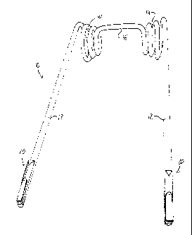
Figure 1 is a perspective view of a double coil spring harrow tine
featuring a two piece cutting edge attachment of a first embodiment of the
present
invention on each downwardly extending shaft of the tine.
Figure 2 is a close up side view of the cutting edge attachment on one
of the shafts of the tine of Figure 1.
Figure 3 is a close up perspective end view of the cutting edge
attachment of Figure 2.
CA 02808697 2013-02-28
7
Figure 4 is a close up side/front perspective view of a cutting edge
attachment of a second embodiment of the present invention.
Figure 5 is a close up perspective end view of the cutting edge
attachment of Figure 4.
Figure 6 is a perspective view of a cutting edge attachment of a third
embodiment of the present invention.
Figure 7 is a front view of the cutting edge attachment of Figure 6.
Figure 8 is a side view of the cutting edge attachment of Figure 6.
Figure 9 is an end view of the cutting edge attachment of Figure 6 from
an upper end thereof.
Figure 10 is an end view of the cutting edge attachment of Figure 6
from a lower end thereof.
Figure 11 is a cross-sectional view of the cutting edge attachment of
Figure 8 as taken along line XI ¨ XI thereof.
DETAILED DESCRIPTION
Figure 1 illustrates application of the present invention to a
conventional double coil spring tine 10 consisting of two shafts 12 depending
downward from the outer ends of a pair of coaxial coils 14 that are
horizontally
spaced apart from one another along their shared horizontal axis by a central
cross-
bar 16. The present invention adds a cutting edge attachment 20 to the lower
end of
each tine shaft 12 to increase the hardness of the structure on the leading
side of
the shaft that engages in the ground during use of the tine.
CA 02808697 2013-02-28
8
More particularly, the illustrated embodiments employ a two-piece
attachment structure in which a base or mounting member 22 is made of a first
material suitable for welded attachment to the tine shaft, and a working or
cutting
edge member 24, 24' of a second harder material is carried at an exposed
position
at the front side of the mounting member 22 to provide improved durability at
the
bottom end of the tine shaft. This provides the benefit of allowing use of a
highly
durable material like tungsten carbide to form the cutting edge of the tine,
while
allowing welded installation of the attachment despite the tungsten carbide's
unsuitability for welded attachment to the spring steel of the tine.
Forming the mounting member 22 of a weld-friendly material such as
chrome carbide, which has a hardness greater than that of the spring steel but
less
than that of the tungsten carbide, thus allows easy installation of the
attachments
with conventional welding techniques for secure, relatively permanent
fastening to
the tine, while the attachment of the cutting edge piece to the mounting
member, for
example by brazing, further improves the durability of the at the bottom end
of the
tine shaft compared to use of the chrome carbide piece alone.
Mounting members 22 of the same shape are used in the two
illustrated embodiments. With reference to Figure 5, a backside 25 of the
mounting
member is arcuately curved in a concave manner to conform with the convex
peripheral surface of the circular-section tine shaft 12 on the front side of
the shaft
that leads the opposing rear side when the tine is conveyed along the ground
by a
harrow or other implement on which the tine is mounted. The mounting member 22
is linear in its length, which runs parallel to the longitudinal axis of the
linear shaft 12
CA 02808697 2013-02-28
9
of the tine. The arcuate curve in the backside of the mounting member lies in
cross-
sectional planes perpendicular to its length, and is uniform over the full
length of the
mounting member. The concave backside of the mounting member spans less than
180-degrees so that the mounting member doesn't fully span the diameter of the
tine
shaft at its conforming interface against the front side of the shaft.
With continued reference to Figure 5, moving forwardly away from its
concave backside placed against the tine shaft, the mounting member 22 has
rear
side walls 26 that flare laterally outward to increase the width of the
mounting
member relative to its point of contact with the shaft. These rear side walls
26 are
both flat and are symmetric to one another across a central longitudinal plane
that
contains the longitudinal axis of the tine shaft and cuts radially through the
apex of
the concave backside of the mounting member. Front side walls 28 are likewise
flat
and symmetric about the central longitudinal plane, and converge forwardly
from the
rear side walls 26, providing a forwardly tapered shape that narrows forwardly
from
the widest point of the mounting member. At the widest point of the mounting
member, i.e. in the plane containing the two parallel edges at which the front
and
rear side walls meet on the opposite sides of the mounting member, the
mounting
member preferably has a width equal to or slightly exceeding the diameter of
the tine
shaft, thus presenting a full width shield over the forward facing half of the
shaft
circumference for optimum protection thereof by the harder mounting member.
At a lower portion 30 of the mounting member 22 the front side walls
28 are truncated by a plane that is parallel to the length of the mounting
member and
parallel to the tangent of the apex of the concave backside of the member,
thus
CA 02808697 2013-02-28
forming a flat front face 32 over the height of this lower portion of the
mounting
member 22. Above this flattened lower portion 30 of the mounting member 22,
the
front side walls 28 are not truncated, and instead intersect with another to
form a
forwardly pointing peak that runs in the lengthwise direction of the mounting
member
5 to define a linear edge 34 at an upper portion 36 of the mounting member.
The
sharpened peak at the front of the upper portion of the mounting member is
believed
to better break up straw during use of the implement, and thereby help the
straw
clear the tine as the implement moves forward.
At the upper portion 36 of the mounting member 22, the intersecting
10 front side walls 28 thus form two sides of a right-angle triangular prism
that runs
upward from the flattened lower portion 30 of the mounting member to the top
end of
the pointed linear edge 34, and whose imaginary third side is formed by the
plane
defined by the maximum width of the cutting member (i.e. the plane containing
the
parallel edges at which the front and rear side walls intersect at both sides
of the
cutting member). At the top of the mounting member 22, the triangular prism
shape
projecting forward from the maximum width of the cutting member is truncated
at an
oblique plane so as to form a triangular upper face 38 that slopes downwardly
and
forwardly from the top end of the member 22.
The mounting member 22 is welded to the tine shaft , for example as
illustrated in the drawings by beads of welding material 40, 42 running
downward
along the shaft at the rear side walls 26 of the mounting member 22 and across
the
bottom end of the mounting member. The obliquely sloped upper end of the
CA 02808697 2013-02-28
11
mounting member reduces the opportunity for straw to build up at the
transition
between the mounting member and the tine shaft during use of the implement.
In the first embodiment of Figures 1 to 3, the cutting edge member 24
is provided in the form of a flat, rectangular, bar-shaped piece of tungsten
carbide.
The flat piece 24 has a length spanning that of the flattened lower portion 30
of the
mounting member, thus extending from the bottom end of the mounting member 22
up to the triangular face 44 at the right angle transition between the peaked
upper
portion 36 of the mounting member 22 and the flattened lower portion 30
recessed
back from the peak 34 of the upper portion. The width of bar likewise spans
the full
width of the flattened front face 32 of the lower portion of the mounting
member 22.
The rectangular rear face of the flat piece 24 sits flush against the
flattened front
face 32 of the mounting member's lower portion. The thickness of the flat
piece 24,
measured from its flat rear face to its opposing flat rectangular front face
46, is the
smallest of the piece's three dimensions, and is less than the distance by
which the
peaked upper portion of the mounting member 22 projects from the flat front
face of
the flattened lower portion of the mounting member 22. The flat front face of
the bar
24 is thus recessed back from the linear edge 34 at the leading peak or point
of the
upper portion of the mounting member 22. The reduced thickness may contribute
to
prevention of straw buildup on the corners of the cutting edge member compared
to
use of a thicker rectangular piece.
Having the flattened front face of the mounting member 22 in a plane
cutting through the front side walls, rather than positioned further back at
or behind
the widest point of the mounting member, acts to keep a notable distance
between
CA 02808697 2013-02-28
12
the rear side wall areas at which the mounting member is welded to the tine
shaft
and the flattened front area at which the cutting edge member 24 is brazed to
the
mounting member 22. This way, when the mounting member is welded onto the tine
shaft sometime after the cutting edge member is brazed to the mounting member,
the heat from the weld does not weaken the brazed joint. Accordingly, the
cutting
edge member can be brazed to the mounting member by the manufacturer, and the
resulting prefabricated attachment assembly can then be installed by a single
process of welding to the tine shaft by an installer (e.g. the implement
owner) at the
site where the implement is normally used, stored or serviced.
The second embodiment of Figures 4 and 5 differs from the first
embodiment only in the shape of the cutting edge member 24', which instead of
a
thin, bar-like rectangular prism, has the shape of an obliquely truncated
triangular
prism. In the second embodiment, the cutting edge member thus has a form more
similar to the upper portion of the mounting member than the flat bar cutting
edge
member 24 of the first embodiment.
The triangular cutting member 24' has a flat rear face that sits flush
against the flat front face of the lower portion of the mounting member 22,
and two
sides walls 48 that converge together forwardly from the flat rear face of the
member
24' to intersect at a linear peak 50. The upper end of the cutting edge member
24' is
a triangular surface lying at a right angle to the flat rear face of the
cutting edge
member 24' so as to abut flush against the matching triangular surface 44 at
the
lower end of the mounting member's upper portion. The lower end of the cutting
edge member 24' is where the piece deviates from its otherwise right-angle
prism
CA 02808697 2013-02-28
13
shape, as the lower end is truncated by an oblique plane to define a
triangular lower
end surface 52 sloping upwardly and forwardly from the lower end of the
mounting
member 22 to the peak 50 of the cutting edge member 24'. The oblique angle of
the
bottom end of the carbide is to add strength as compared as to if the lower
end of
the carbide was at a 90-degree angle, which could create a sharper point at
the
lower end of the linear peak 50.
The thickness of the, triangular cutting edge member, i.e. the
perpendicular distance from its flat rear face to its forward peak, matches
the
perpendicular distance by which the upper portion of the mounting member
projects
forwardly from the flat front face of the lower portion. The flat rear face of
the
triangular cutting edge member 24' has a width matching that of the flat front
face of
the lower portion of the mounting member 22, and the angle at which the side
walls
48 of the cutting edge member 24' converge matches the angle of convergence of
the front side walls 28 of the mounting member. Accordingly, the linear edge
formed
by the peak 50 of the cutting edge member 24' forms a continuous, in-line
extension
of the linear peak edge 34 of the upper portion of the mounting member 22, and
the
side walls 48 of the cutting edge member 24' each form a continuous, coplanar
extension of the respective front side wall 28 of the mounting member 22.
In each embodiment, the forwardly narrowing shape of the tapered
upper portion of the mounting member forms a sharpened leading edge of the
mounting member at a height spaced a distance upward from the lower end of the
tine shaft. In the second embodiment, the cutting member likewise tapers
forwardly
in order to narrow to a sharpened cutting edge aligned with the sharpened
leading
CA 02808697 2013-02-28
14
edge of the mounting member. In the first embodiment, the flat front face of
the
cutting edge member instead forms a wider, flat cutting edge set back from the
sharpened leading edge of the mounting member. In each case, the lower portion
of
the mounting body carries a distinct, separately formed body of tungsten
carbide to
provide optimum durability and wear resistance at a location rising a short
distance
upward from the bottom end of the tine shaft, where the most ground contact
will
occur during use of the tine. The exposed upper portion of the mounting body,
though not as strong as the cutting edge body, still provides increased wear
resistance over a slightly higher portion of the tine shaft where some contact
with the
earth is still expected, compared to use of a tine without any hardened
cutting edge
attachment. Having the mounting body run the full length of the cutting edge
body in
front of it ensures a strong, secure connection of the cutting edge body to
the tine.
Figures 6 to 10 illustrate a third embodiment of similar form to the first
embodiment, but with some notable changes including replacement of the single
bar-shaped piece of tungsten carbide with two shorter flat rectangular bar-
shaped
pieces 24a, 24b abutted end to end to form the cutting edge member 24", and
use of
a tapered shape at both the upper and lower portions of the mounting member
22'
that increases the thickness of each portion when moving downward along the
lengthwise dimension of the mounting member. The upper portion thus not only
grows narrower moving in the forward direction when mounted on the tine in
order
produce a forwardly pointing peak 34', but also grows thinner (i.e. smaller in
the
fore/aft direction) moving upwardly along the tine, as does the lower portion.
The
=
CA 02808697 2013-02-28
upper portion also tapers in width at an upper region thereof toward the top
end of
the mounting member.
Each piece 24a, 24b of the two-piece cutting edge arrangement of the
third embodiment occupies a respective half of the overall length of the
mounting
5 member's lower portion, and each substantially spans the full width of
the flattened
front face of the lower portion of the mounting member. The use of a plural
number
of smaller carbide pieces each spanning a different respective partial portion
of the
flattened front face of the mounting member reduces the risk of breakage of
the
carbide in the heating and cooling cycle it experiences during welding of the
10 mounting member to the tine.
The tapered thickness of the mounting member 22' of the third
embodiment is best shown in Figure 8. Turning briefly to Figure 10, as in the
other
embodiments, the plane of the flattened front face 32' of the mounting member
is
perpendicular to a radial plane P that contains the apex 60 of the uniform-
radius
15 arcuate rear side of the mounting member and the axis A from which the
radius R of
the arcuate rear side is measured. However, unlike the other embodiments, the
plane of the flattened front face 32' of the lower portion of the mounting
member 22'
is not parallel to axis A (which is generally coincident with the longitudinal
axis of the
tine shaft when the mounting member is installed thereon). Instead, referring
to
Figure 8, the plane of the flattened front face 32' is obliquely sloped
relative to this
axis A at a small angle so that the lower portion of the mounting member of
the
grows thicker moving in a downward direction along the length of the mounting
member. This thickness dimension may be measured as the distance between the
CA 02808697 2013-02-28
16
flattened front face 32' and the apex 60 of the mounting member's concave
backside. In other words, the plane of the front face 32' is tilted out of
parallel
alignment with a tangential plane T at the apex 60 of the concave rear side of
the
mounting member.
Similarly, the peak edge 34' of the upper portion 36' of the mounting
member is obliquely sloped at a small angle relative to axis A and tangential
plane T
so that the upper portion of the mounting member also increases in thickness
(for
example, as measured between the apex 60 of its arcuately concave rear side
and
its leading peak 34') as you move in the downward direction along the axis A.
In the
illustrated embodiment, the peak edge 34' of the upper portion and the
flattened
front face 32' of the lower portion are parallel, i.e. sloped at the same
angle relative
to the axis A or tangential plane T.
When the mounting member is installed on a tine, it thus projects
further forwardly from the tine at the lower end of the peak 34' than over the
remainder of the upper portion, and projects further forwardly from the tine
at the
lower end of the lower portion than over the remainder of the lower portion.
In the
illustrated embodiment, the bottom edge of the flattened front face 32' of the
lower
carbide piece 24b is generally the same radial distance from axis A as the
lower end
of the upper portion's peak 34' so that the carbide pieces 24a, 24b of the
cutting
edge portion 24" project no further forward from the tine than the peak 34' of
the
mounting portion. That is, the combined thickness of the lower carbide piece
24b
and the mounting member at the lower end thereof is generally equal to, and
does
CA 02808697 2013-02-28
17
not exceed the thickness of the mounting member at the lower end of the upper
portion thereof.
As a result of this tapered configuration of the upper and lower portions
of the mounting member, there is a less dramatic transition from the straight
metal
tine shaft or bar to the top of the mounting member when installed, while a
significant material thickness at the bottom end of the mounting member
remains
intact in order to provide adequate support and room for welding of the
mounting
member to the tine.
In order to maintain a uniform width over the full length of the flattened
front face 32' of the lower portion of the mounting member to allow for a
uniform
width of the cutting edge member to be mounted thereon, while still retaining
a
uniform overall width of the mounting member over the lower portion and over
the
peaked lower part of the upper portion, an angle of slope by which each side
of the
mounting member intersects the plane of the flattened front face 32' of the
mounting
member 22' varies as you move along the lengthwise direction of the lower
portion
of the mounting member. That is, the side of the mounting member slopes more
dramatically inward toward the lateral center of the mounting member at the
top end
of the flattened front face 32' than at the lower end so that the resulting
width of the
flattened front face is the same at both the thinner top end of the mounting
member's
lower portion and the thickener bottom end of the mounting member's lower
portion.
This is best illustrated by reference to Figures 10 and 11, where the
acute angle measured between the plane of the flattened front face 32' and the
plane of side wall joined thereto on each side of the mounting member is
labelled 0
CA 02808697 2015-11-03
18
at the lower end of the mounting member (Figure 10), and is labelled (1) in a
cross-
sectional plane near the upper end of the lower portion (Figure 11), and (1)
is less
than e. The cross-section of the mounting member is symmetric about plane P,
and
so although the side wall to front face angle is marked only one side of the
mounting
member in each of these figures, the other side is a mirror image, and thus
features
the same angular configuration between the respective side wall and the
flattened
front face. The angle of each of these side walls of the mounting member
varies
smoothly over the lengthwise direction from one end of the lower portion to
the
other.
To further increase the smoothness of the transition between the upper
end of the mounting member and the tine shaft, the upper portion of the
mounting
member of the third embodiment is not only tapered in thickness by the slope
of the
plane of the upper face 38', but additionally tapers in width, as best seen at
62 in
Figure 7 by convergence of the side walls toward one another in a manner
symmetric about the plane P from near the prism-shaped lower part of the upper
portion to the very top end of the upper portion.
Since various modifications can be made in my invention as herein
above described, and many apparently widely different embodiments of same made
within the scope of the claims without departure from such scope, it is
intended that
all matter contained in the accompanying specification shall be interpreted as
illustrative only and not in a limiting sense.