Note: Descriptions are shown in the official language in which they were submitted.
CA 02808770 2013-03-07
BONDED COMPOSITE AIRFOIL AND FABRICATION METHOD
BACKGROUND INFORMATION
1. Field:
The present disclosure generally relates to
airfoils, such as a wing box for an aircraft, and deals
more particularly with an airfoil construction having a
composite outer skin bonded to wing spars.
2. Background:
Aircraft wings and/or control surfaces may employ a
framework of spars, ribs and stringers that are covered
with an outer skin. The
spars may carry a majority of
the wing load while the ribs both stiffen the wing and
provide an airfoil shape for the wing skin. In the case
of metal wing constructions, metal structures may be
attached to the metal spars using fastener joints.
However, the use of fastener joints may present
difficulties in composite spar wing and control surface
designs, in part because composites may have a lower
bearing capacity than metals.
Accordingly, composite
wing constructions using fasteners may require
reinforcements to increase their fastener bearing
capacity in joint areas. The need to add reinforcements
in the wing may reduce airfoil performance, add undesired
weight to the aircraft and/or increase manufacturing
costs.
Accordingly, there is a need for bonded joining of a
composite wing and/or control surface structure and
related fabrication method that may reduce or eliminate
the need for fasteners in joints between a wing spar and
1
CA 02808770 2013-03-07
,
a connected structures skin. There is also a need for an
airfoil design such as a wing box that simplifies
fabrication of wing components and allows pre-cured
composite wing skins to be attached to pre-cured
composite spars using adhesive bonding techniques in a
secondary bonding operation.
SUMMARY
The disclosed embodiments provide an airfoil, such
as an airplane wing box or control surface, and a related
fabrication method that allows precured composite
sandwich panel skins to be adhesively bonded to precured
composite sandwich spars in a secondary bonding
operation, thereby reducing or obviating the need for
fastened joints between the skins and the spars. Use of
composite sandwich panel skins and spars provides the
airfoil with the required stiffness while reducing part
count, complexity and weight.
Precuring the wing skins
and wing spars separately in an autoclave before the
secondary bonding operation may reduce product
inconsistencies, improve the quality of the airfoil,
simplify production processes and reduce manufacturing
flow time. Load transfer through the skin-to-spar bonds
may be reduced by integrating the spar caps into the
spars, and by employing spar caps that are reinforced
laminates. The spar caps are substantially aligned with
the composite sandwich panel skins.
Spar weight is
minimized by employing spar webs that are of a honeycomb
sandwich construction. Use of
composite sandwich panel
skins may reduce or eliminate the needs for longitudinal
wing stringers, while reducing the number of, or spacing
between wing ribs.
2
CA 02808770 2016-08-29
According to one disclosed embodiment, there is
provided an airfoil comprising: at least one wing skin
panel including an outer wing skin, an inner wing skin and
a panel core sandwiched between the inner and outer wing
skins; at least one spar having a spar web and a spar cap,
the spar web having a spar web core, and the spar cap
having a spar cap core extending in a generally lateral
direction to the spar web and being generally aligned with
the panel core and forming a joint with the panel core,
wherein the spar cap core is connected to the spar web
core; and an adhesive bond joint between the wing skin
panel and the spar.
The outer wing skin may overlap the joint and may be
in face-to-face contact with the spar cap. The
spar may
include an inner facesheet that overlaps the joint, and
each of the outer wing skin and the inner facesheet may be
a fiber reinforced composite resin. The spar may include
a noodle connecting the spar cap core with the spar web
core. The
spar may include inner and outer facesheets,
and the spar cap core, the spar web core and the noodle
may be sandwiched between the inner and outer facesheets.
The spar cap core may be a substantially solid laminate,
and the spar web may include a honeycomb core. The spar
may include two C-members arranged back-to-back and may
respectively have oppositely extending flanges forming the
spar cap, and the outer skin may overlap and may be in
face-to-face contact with the flanges.
According to another disclosed embodiment, there is
provided an airfoil comprising: at least one spar having a
spar web having a web core, and at least one spar flange
on one end of the web; an outer wing skin in face-to-face
contact with the flange; and a bond joint attaching the
3
CA 02808770 2016-08-29
,
spar flange to the outer wing skin, wherein the flange
includes a flange core having a density sufficient to
transmit substantially all of a load placed on the outer
wing skin to the spar web, and wherein the flange core is
connected to the web core.
Each of the spar and the outer skin may be a
composite, and the spar may include a noodle connecting
the flange with the web.
The spar may include an inner
spar facesheet, an outer spar facesheet, and a web core
sandwiched between the inner and outer spar facesheets,
wherein the flange core may be sandwiched between the
inner and outer spar facesheets. The flange core may be a
substantially solid composite laminate, and the web core
may be a honeycomb. The spar may include first and second
spar members each having substantially C-shaped cross
section, and the spar members may be joined together back-
to-back.
The airfoil may further comprise an inner wing
skin, a wing skin core sandwiched between the outer wing
skin and the inner wing skin.
The flange core and the
wing skin core may be substantially aligned with each
other and are arranged side-by-side to form a joint, and
the outer wing skin may overlap the joint.
The spar may
include inner and outer facesheets, the spar may include a
noodle connecting the flange core with the web core, and
the flange core, the web core and the noodle may be
sandwiched between the inner and outer facesheets.
4
CA 02808770 2016-08-29
According to another disclosed embodiment, there is
provided an airfoil comprising: at least one wing skin
panel including an outer wing skin, an inner wing skin
and a panel core sandwiched between the inner and outer
wing skins; at least one spar having a spar web and a
spar cap, the spar web having a spar web core, and the
spar cap having a spar cap core substantially
horizontally aligned with the panel core and forming a
joint with the panel core, wherein the spar cap core is
connected to the spar web core; and an adhesive bond
joint between the wing skin panel and the spar.
According to another disclosed embodiment, there is
provided an airfoil comprising: at least one spar having
a spar web having a web core, and at least one composite
spar flange on one end of the web; an outer layer of a
sandwich-structured composite wing skin in face-to-face
contact with the composite spar flange; and a bond joint
attaching the composite spar flange to the outer layer,
wherein the composite spar flange includes a flange core
having a density sufficient to transmit substantially all
of a load placed on an outer wing skin to the spar web,
and wherein the flange core is connected to the web core.
According to still another embodiment, a procured
front composite spar, a precured rear composite spar, at
least one procured wing skin panel including an outer
wing skin, and adhesive bond joints attaching the
precured wing skin panel to each of the front and rear
precured composite spars. The wing may further comprise a
precured composite leading edge assembly, and the leading
edge assembly includes an outer facesheet
4a
CA 02808770 2013-03-07
,
overlapping and bonded to the precured front composite
spar.
Each of the precured front spar and the precured
rear spar is a sandwich panel construction having an
inner spar facesheet and an outer spar facesheet.
The
wing skin panel is a sandwich construction and includes
an inner wing skin. The outer wing skin overlaps and is
bonded to the outer spar facesheet, and the inner spar
facesheet overlaps and is bonded to the inner wing skin.
According to a further embodiment, a method is
provided of fabricating an airfoil. The method comprises
assembling and precuring a composite wing skin,
assembling and precuring a composite spar, and attaching
the composite skin to the composite spar by adhesively
bonding the composite skin to composite spar.
Assembling the composite spar includes sandwiching a spar
web core and a spar cap core between inner and outer
composite spar facesheets, and connecting the spar web
core with the spar cap core by placing a noodle between
spar web core and the spar cap core.
Assembling the
composite wing skin includes forming composite sandwich
by sandwiching a wing skin core between inner and outer
composite wing skins, and curing the composite skin
sandwich, and bonding the composite wing skin to the
composite spar includes bonding each of the inner and
outer wing skins facesheets to the composite spars.
Attaching the composite wing skin to the composite spar
includes forming a joint between the wing skin core and a
core of the composite spar, and overlapping the outer
wing skin over the joint. Attaching the composite wing
skin to the composite spar also includes overlapping an
inner composite facesheet of the spar over the joint.
5
CA 02808770 2013-03-07
According to an aspect of the present disclosure
there is provided An airfoil, comprising at least one
wing skin panel including an outer wing skin, an inner
wing skin and a panel core sandwiched between the inner
and outer wing skins, at least one spar having a spar web
and a spar cap, the spar cap having a spar cap core
generally aligned and forming a joint with the panel core
and an adhesive bond joint between the wing skin panel
and the spar. Advantageously the outer wing skin overlaps
the joint and is in face-to-face contact with the spar
cap. Advantageously the spar includes an inner facesheet
that overlaps the joint. Preferably each of the outer
wing skin and the inner facesheet is a fiber reinforced
composite resin. Advantageously the spar web includes a
spar web core, and the spar includes a noodle connecting
the spar cap core with the spar web core. Preferably, the
noodle is a sheet molding compound. Preferably the spar
includes inner and outer facesheets, and the spar cap
core, the spar web core and the noodle are sandwiched
between the inner and outer facesheets. Advantageously
the spar cap core is a substantially solid laminate and
abuts the panel core, and the spar web includes a
honeycomb core. Advantageously the spar includes two C-
members arranged back-to-back and respectively have
oppositely extending flanges forming the spar cap, and
the outer skin overlaps and is in face-to-face contact
with the flanges.
According to an aspect of the present disclosure
there is provided an airfoil, comprising at least one
spar having a spar web and at least one spar flange on
one end of the web, an outer wing skin in face-to-face
contact with the flange, and a bond joint attaching the
6
CA 02808770 2013-03-07
spar flange to the outer wing skin, wherein the flange
includes a flange core having a density sufficient to
transmit substantially all of a load placed on the outer
wing skin to the spar web. Advantageously each of the
spar and the outer wing skin is a composite, and the spar
includes a noodle connecting the flange with the web.
Preferably the spar includes an inner spar facesheet, an
outer spar facesheet, a web core sandwiched between the
inner and outer spar facesheets, and wherein the flange
core is sandwiched between the inner and outer spar
facesheets. Preferably the flange core is a substantially
solid composite laminate, and the web core is a
honeycomb. Advantageously the spar includes first and
second spar members each having substantially C-shaped
cross section, and the spar members are joined together
back-to-back. Advantageously The airfoil
further
comprises an inner wing skin, a wing skin core sandwiched
between the outer wing skin and the inner wing skin, and
wherein the flange core and the wing skin core are
substantially aligned with each other and are arranged
side-by-side to form a joint, and the outer wing skin
overlaps the joint. Advantageously the spar includes
inner and outer facesheets, the web includes a web core,
the spar includes a noodle connecting the flange core
with the web core, and the flange core, the web core and
the noodle are sandwiched between the inner and outer
facesheets. Preferably the web core has a density less
than a density of the flange core.
According to an aspect of the present disclosure
there is provided a wing, comprising a precured front
composite spar a precured rear composite spar at least
one precured wing skin panel including an outer wing skin
7
CA 02808770 2013-03-07
,
,
and adhesive bond joints attaching the precured wing
skin panel to each of the front and rear precured
composite spars. Advantageously the wing further
comprises a precured composite leading edge assembly, the
leading edge assembly including an outer facesheet
overlapping and bonded to the precured front composite
spar. Advantageously each of the precured front spar and
the precured rear spar is a sandwich panel construction
having an inner spar facesheet and an outer spar
facesheet, the wing skin panel is a sandwich construction
and includes an inner wing skin, the outer wing skin
overlaps and is bonded to the outer spar facesheet, and
the inner spar facesheet overlaps and is bonded to the
inner wing skin.
According to an aspect of the present disclosure
there is provided a method of fabricating an airfoil,
comprising assembling and precuring a composite wing
skin, assembling and precuring a composite spar; and,
attaching the composite wing skin to the composite spar
by adhesively bonding the composite wing skin to
composite spar. Advantageously assembling the composite
spar includes, sandwiching a spar web core and a spar cap
core between inner and outer composite spar facesheets,
and connecting the spar web core with the spar cap core
by placing a noodle between spar web core and the spar
cap core. Advantageously assembling the composite wing
skin includes forming a composite skin sandwich by
sandwiching a wing skin core between inner and outer
composite wing skins, and curing the composite skin
sandwich, and bonding the composite wing skin to the
composite spar includes bonding each of the inner and
outer wing skins facesheets to the composite spars.
8
CA 02808770 2015-05
Preferably attaching the composite wing skin to the
composite spar includes forming a joint between the wing
skin core and a core of the composite spar, and
overlapping the outer wing skin over the joint.
Preferably attaching the composite wing skin to the
composite spar includes overlapping an inner composite
facesheet of the spar over the joint.
The features, functions, and advantages can be
achieved independently in various embodiments of the
present disclosure or may be combined in yet other
embodiments in which further details can be seen with
reference to the following description and drawings.
BRIEF DESCRIPTION OF THE DRAWINGS
The advantageous embodiments, as well as a preferred
mode of use, further objectives and advantages thereof,
will best be understood by reference to the following
detailed description of an advantageous embodiment of the
present disclosure when read in conjunction with the
accompanying drawings, wherein:
FIG. 1 is an illustration of a flow diagram of
aircraft production and service methodology.
FIG. 2 is illustration of a block diagram of an
aircraft.
FIG. 3 is an illustration of a perspective cross
sectional view of a wing box having wing skin panels
9
CA 02808770 2013-03-07
bonded to wing spars with integrated caps according to
the disclosed embodiments, leading and trailing edge
assemblies being indicated in the phantom.
FIG. 4 is a cross sectional view taken in the
direction shown as FIG. 4 in FIG. 3, the leading edge
shown in full lines but the trailing edge not shown.
FIG. 5 is an illustration of a cross sectional view
showing how the leading edge assembly and the pre-cured
top wing skin panel are assembled onto the pre-cured
front spar.
FIG. 6 is an illustration similar to FIG. 5 but
showing the components in a fully assembled state.
FIG. 6A is an illustration similar to FIG. 6, but
showing an alternate embodiment employing spar haFving a
single cap core and a single web core.
FIG. 6B is an illustration similar to FIG. 6A, but
showing another embodiment in which the web core is
attached directly to the cap core.
FIG. 7 is an illustration showing the top wing skin
panel being loaded onto the rear spar during the assembly
process.
FIG. 8 is an illustration similar to FIG. 7 but
showing the components in a fully assembled state, the
trailing edge assembly being indicated in the phantom.
CA 02808770 2013-03-07
FIG. 9 is an illustration of a perspective view
showing components of the trailing edge assembly attached
to a wing box.
FIG. 10 is an illustration of a flow diagram of a
method of fabricating a bonded composite airfoil.
DETAILED DESCRIPTION
The disclosed embodiments involve a bonded composite
airfoil and a related fabrication method. The embodiments
may find use in a variety of potential applications,
particularly in the transportation industry, including
for example, aerospace, marine, automotive applications
and other applications where light weight airfoil-like
structures are employed. Thus, referring now to FIGS. 1
and 2, embodiments of the disclosure may be used in the
context of an aircraft manufacturing and service method
as shown in FIG. 1 and an aircraft 22 as shown in FIG.
20 2.
Aircraft applications of the disclosed embodiments
may include, for example, without limitation, wings 54, a
vertical stabilizer 58 and horizontal stabilizers 60
forming part of the airframe 38, to name only a few.
During pre-production, exemplary method 20 may include
specification and design 24 of the aircraft 22 and
material procurement 26.
During production, component
and subassembly manufacturing 28 and system integration
of the aircraft 22 takes place.
Thereafter, the
aircraft 22 may go through certification and delivery 32
30 in order to be placed in service 34. While in service by
a customer, the aircraft 22 is scheduled for routine
maintenance and service 36, which may also include
modification, reconfiguration, refurbishment, and so on.
11
CA 02808770 2013-03-07
Each of the processes of method 20 may be performed
or carried out by a system integrator, a third party,
and/or an operator (e.g., a customer). For
the purposes
of this description, a system integrator may include
without limitation any number of aircraft manufacturers
and major-system subcontractors; a third party may
include without limitation any number of vendors,
subcontractors, and suppliers; and an operator may be an
airline, leasing company, military entity, service
organization, and so on.
As shown in FIG. 2, the aircraft 22 produced by
exemplary method 20 may include an airframe 38 with a
plurality of systems 40 and an interior 42. Examples of
high-level systems 40 include one or more of a propulsion
system 44, an electrical system 46, a hydraulic system
48, and an environmental system 50. Any number of other
systems may be included. The airframe 38 may include a
fuselage 52, wings 54, a vertical stabilizer 58,
horizontal stabilizers 60 and one or more control
surfaces 62 such as leading and trailing edge assemblies
(not shown). Each of the wings 54 may include a wing box
56, sometimes also referred to as a torque box. The
wings 54, stabilizers 58, 60 and control surfaces are
covered by skins 64. As used herein in connection with
aircraft applications, the term -airfoil" is intended to
include, but is not limited to wings 54, vertical
stabilizer 58, horizontal stabilizers 60, and control
surfaces 62.
Systems and methods embodied herein may be employed
during any one or more of the stages of the production
12
CA 02808770 2013-03-07
and service method 20. For
example, components or
subassemblies corresponding to production process 28 may
be fabricated or manufactured in a manner similar to
components or subassemblies produced while the aircraft
22 is in service. Also,
one or more apparatus
embodiments, method embodiments, or a combination thereof
may be utilized during the production stages 28 and 30,
for example, by substantially expediting assembly of or
reducing the cost of an aircraft 22.
Similarly, one or
more of apparatus embodiments, method embodiments, or a
combination thereof may be utilized while the aircraft 22
is in service, for example and without limitation, to
maintenance and service 36.
Principles of the disclosed embodiments may be
employed in connection with the fabrication of a variety
of airfoils for various applications. For example, FIGS.
3 and 4 illustrate an airfoil comprising a bonded, panel-
stiffened, composite wing box 56 forming part of an
airplane wing 54 (FIG. 2). A
leading edge assembly 70
having a leading edge 70a may be attached to the front of
the wing box 56, and a trailing edge assembly 72 having a
trailing edge 72a may be attached to the rear of the wing
box 56.
The wing box 56 includes at least a front spar 66
and a rear spar 68. The
front spar 66 is generally I-
shaped in cross section, and the rear spar 68 is
generally C-shaped in cross section, however other cross
sectional shapes are possible. The
front spar 66
includes a front spar web 82, and upper and lower spar
caps 84, 86 that are respectively integrated into the
opposite top and bottom ends of the web 82.
Similarly,
13
CA 02808770 2013-03-07
the rear spar 68 includes a rear spar web 88 and upper
and lower spar caps 90, 92 that are integrated into the
opposite top and bottom ends of the web 88. Depending on
the application, the front and/or rear spar 66, 68 may be
in the form of other webbed structures, such as, without
limitation, "J", "Z" and "T" structures. As will be
explained below, each of the spar caps 84, 86, 90, 92 may
comprise a single flange or a double flange that may be a
reinforced composite resin laminate, depending on the
application and particular configuration of the wing box
56.
A top wing skin panel 74 and a bottom wing skin
panel 76 cover the wing box 56 and are bonded to the
spars 66, 68 at skin-to-spar bonded corner joints 78,
thereby reducing or eliminating the need for fastened
joints between wing skin panels 74, 76 and the spars 66,
68. The
upper spar caps 84, 90 are generally aligned
with and integrated into the top wing skin panel 74, and
the lower spar caps 86, 92 are generally aligned with and
integrated into the lower wing skin panel 76.
Although
not shown in the drawings, in some embodiments, the wing
box 56 may optionally include ribs that are spaced apart
in the span-wise direction of the wing box 56 and are
adhesively bonded to the spars 66, 68 and/or to the top
and bottom wing skin panels 74, 76 respectively.
As will be discussed below in more detail, the top
and bottom wing skin panels 74, 76 each include an outer
composite wing skin 146 that covers and is bonded to the
spars 66, 68, thereby forming a substantially continuous,
aerodynamic outer surface 147 on the wing 54 (FIG. 2),
which may have a desired outer wing surface contour. The
14
CA 02808770 2013-03-07
top and bottom wing skin panels 74, 76 are of a sandwich
construction, reinforcing the wing box 56 sufficiently
such that stringers (not shown) may not be required, and
the number of ribs (not shown) needed for a particular
application may be reduced. The use of composite sandwich
construction for both the wing skin panels 74, 76 and the
spars 66, 68 also may reduce part count, complexity and
weight.
The top wing skin panel 74 and the bottom wing skin
panel 76 may be precured and respectively attached at the
bonded corner joints 78 to a precured front spar 66 and a
precured rear spar 68 in a secondary bonding operation.
Precuring the wing skin panels 74, 76 and the spars 66,
68 separately in an autoclave before the secondary
bonding operation may reduce product inconsistencies,
improve the quality of the airfoil, simplify production
processes and reduce manufacturing flow time.
Each of
the front and rear spars 66, 68 respectively, and the top
and bottom wing skin panels 74, 76 respectively, may be
of a composite sandwich panel construction described
later in more detail. Top
and bottom wing skin panels
74, 76 are respectively bonded to front and rear spars
66, 68 by a layer 80 (FIGS. 5 and 7) of structural
adhesive that forms the bonded corner joints 78.
The bonded corner joints 78 may transfer relatively
minimal loads between the wing skin panels 74, 76 and the
spars 66, 68, including inertial and air loads.
Integration of the spar caps 84, 86, 90, 92 into the
corresponding spar webs 82, 88 along with use of a
reinforced composite resin laminate in the caps 84, 86,
90, 92 may reduce the load transfer through the bonded
CA 02808770 2013-03-07
corner joints 78. Moreover, substantial alignment of the
centerlines 159 (see FIGS. 6 and 8) of spar caps 84, 86,
90, 92 with the wing skin panels 74, 76 may enhance
efficient load transfer from the outer wing skin 146 to
spar webs 82, 88.
A leading edge assembly 70 (FIGS. 4-6) may be
attached to the front spar 66, and a trailing edge
assembly 72 (FIGS. 3, 8 and 9) having a trailing edge 72a
may be attached to the rear spar 68. As
best seen in
FIG. 4, the leading edge assembly 70 may comprise,
without limitation, a composite laminate skin 104
stiffened by a stiffener spar 106 that extends in the
span-wise direction of the leading edge assembly 70. It
should be noted here that the leading edge assembly 70
shown in the drawings is merely illustrative of a wide
range of leading edge configurations that may be employed
with the disclosed bonded wing box 56.
Other auxiliary
boxes, control surfaces or structures (all not shown) may
be attached to the wing box 56.
Attention is now directed to FIGS. 5 and 6, which
illustrate additional details of the front spar 66 and
the bonded corner joints 78. The
front spar 66 broadly
includes first and second spar members 120, 122 that are
each generally C-shaped in cross section and are arranged
back-to-back with each other to form a spar shape that is
substantially I-shaped in cross section. The
upper and
lower front spar caps 84, 86 (FIGS. 3 and 4) each
includes a pair of flanges 124, 126 respectively
extending forward and aft which are generally aligned and
integrated with the wing skin panels 74, 76.
16
CA 02808770 2013-03-07
FIG. 5 illustrates a leading edge assembly 70 and a
top skin panel 74 being loaded onto the front spar 66 in
preparation for a bonding operation. A
layer 80 of a
suitable structural adhesive such as an adhesive paste is
applied between the mating surfaces of the spar 66, the
leading edge assembly 70 and the top skin panel 74. In
the example shown in FIG. 5, the adhesive layer 80 has
been applied to the front spar 66, however in other
embodiments, the layer 80 of structural adhesive may be
instead applied to the leading edge assembly 70 and to
the top skin panel 74, or to each of the front spar 66,
the leading edge assembly 70 and the top skin panel 74.
As will be discussed below, the leading edge
assembly 70, the top wing skin panel 74 and the front
spar 66 may all be fully cured before they are assembled
together (shown by the arrows 156) and adhesively bonded.
The assembly process may be carried out by placing the
front spar 66 in a suitable alignment and holding fixture
(not shown) and then applying the adhesive layer 80,
followed by placement of the leading edge assembly 70 and
the top wing skin panel 74 onto the front spar 66.
Alternate assembly techniques and orders of assembly may
be possible.
Following the assembly process, the layer
80 of bonding adhesive may be thermally cured by
processing the wing box 56 in an autoclave. Other cure
techniques, such as out-of-autoclave or oven processing,
may be possible, depending on the type of bonding
adhesive used.
Each of the spar members 120, 122 is a sandwich
panel construction in which a spar web core 128 and a
spar cap core 130 are sandwiched between inner and outer
17
CA 02808770 2013-03-07
composite spar facesheets 132, 134 respectively. Each of
the inner and outer spar facesheets 132, 134 may comprise
a composite laminate such as multi-ply, fiber reinforced
composite resin, formed from a unidirectional prepreg in
which the plies have multiple fiber orientations chosen
to optimize performance. The
spar cap cores 130 which
respectively form part of the front spar flanges 124,
126, may each comprise a solid, fiber reinforced
composite resin laminate, sometimes referred to as a
"densepack", although other spar cap core materials
exhibiting the required strength and rigidity may be
possible. As will be discussed below, the solid, fiber
reinforced composite resin laminate spar flanges 124, 126
are precured and then co-bonded to inner and outer spar
facesheets 132, 134 in a "green" state before the front
spar 66 is cured.
The spar web cores 128 may each comprise a suitable
lightweight honeycomb construction, which may or may not
be filled or "potted" with a suitable material, although
other types of lightweight cores may be possible. The
spar web cores 128 may have a density that is less than
that of the spar cap cores 130 in order to reduce the
overall weight of the spar 66, however, in some
applications, the spar web cores 128 may have a density
that is equal to or greater than that of the spar cap
cores 130. Generally, the density of the spar cap cores
130 is sufficiently high such that spar caps 84, 86 are
able to transfer substantial loads from the outer wing
skins 146 to the spar web 82, and limit the amount
loading transferred through the bonded corner joints 78
to shear loads transferred to the bonded corner joints
from the inner and outer skins 144, 146.
18
CA 02808770 2013-03-07
,
Because the spar cap cores 130 and the spar web
cores 128 may be made from differing materials, e.g. a
laminate and a honeycomb respectively, a void may be
present between these two cores 128, 130 which may be
filled with a noodle 136 that may comprise layers of a
structural adhesive, a multi-ply prepreg or other
suitable filler materials and assists in connecting and
integrating the two core 128, 130 with each other. In
one embodiment, the noodle 136 may comprise a sheet
molding compound in order to reduce the axial stiffness.
Similarly, a void may be present between adjacent
radiused corners 137 of the flanges 124, 126 that may be
filled with a noodle 138 which may comprise layers of a
structural adhesive, a multi-ply prepreg, a sheet molding
compound or other suitable fillers. The
inner spar
facesheets 132 extend outwardly beyond the corresponding
spar cap cores 130 to form forward and aft spar facesheet
lips 140a, 140b, respectively which overlap the bottom of
the spar cores 130.
Similarly, a portion 146a of the
outer wing skin 146 overlaps the top of the cores 130.
The top and bottom overlap of the cores 130 by fiberous
reinforcements in the outer wing skin 146 and the spar
facesheet lips 140a, 140b assist in structurally
stabilizing the spar cap cores 130.
As will be discussed in more detail below, the spar
members 120, 122 are assembled in a green or uncured
state, back-to-back, along with the noodle 136 and then
fully cured to form a fully assembled pre-cured front
spar 66 before being bonded to the top and bottom wing
skin panels 74, 76. Each of the top and bottom wing skin
panels 74, 76 comprises a skin core 142 sandwiched
19
CA 02808770 2013-03-07
between inner and outer composite wing skins 144, 146.
Each of the inner and outer composite wing skins 144, 146
may comprise a composite laminate such as multi-ply,
fiber reinforced composite resin formed of unidirectional
prepreg in which the plies have multiple fiber
orientations chosen to optimize performance. The
wing
skin core 142 may comprise a honeycomb construction and
may be contoured along with the outer composite wing skin
146 to form an outer surface 147 having a desired wing
contour. A
portion 146a of the outer wing skin 146
extends beyond the wing skin core 142 and overlaps and
covers substantially the entire length of the front spar
cap 84. The
leading edge of the outer wing skin is
tapered at 154. The
outer wing skin portion 146a is
adhesively bonded to the outer spar facesheets 134 and to
the noodle 138. The
sandwich construction of the wing
skin panels 74, 76 employing a honeycomb core 142 as
described above may result in a wing skin that has
sufficient strength and rigidity such that skin
stiffeners or reinforcements, such as stringers (not
shown) may not be required, or such that the number of
stiffeners required for a given application is
substantially reduced.
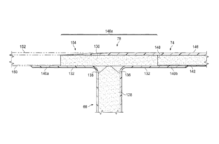
The spar cap core 130 of spar member 122 is aligned
side-by-side with and abuts adjacent wing skin panel core
142, forming a joint 148 (FIG. 6) between the spar cap 84
and the wing skin panel 74 that is overlapped on the top
by the outer wing skin 146 and on the bottom by a
rearwardly extending lip 140 of one of the inner
facesheets 132. Although the joint 148 shown in FIG.6 is
a butt joint, other types of joint configurations are
possible, such as, for example and without limitation, a
CA 02808770 2013-03-07
scarf joint, a lap joint or a step lap joint. The outer
spar facesheets 134 are in face-to-face contact with the
outer wing skin 146, and the inner spar facesheets 132
are in face-to-face contact with the inner wing skin 144.
The forward spar facesheet lip 140a overlaps and is
adhesively bonded to the inner facesheet 150 of the
leading edge assembly 70, and the rear spar inner
facesheet lip 140b is adhesively bonded to the inner skin
144 of the wing skin panel 74. The
outer facesheet 152
of the leading edge assembly 70 is tapered at 155 to
substantially match and overlap the taper 154 of the
outer wing skin 146, and together form a tapered lap
joint at 157. The
outer leading edge facesheet 152 may
be adhesively bonded to the outer wing skin 146 along the
lap joint 157. The bonded attachment of the bottom wing
skin panel 76 (FIGS. 3 and 4) to the front spar 66 may be
substantially the same in detail as the attachment of the
top wing skin panel 74 to the front spar 66 described
above.
FIG. 6A illustrates an alternate embodiment of the
front spar 66 having a single spar web core 128
sandwiched between facesheet 132 and a single spar cap
core 130. In
this example, the spar cap core 130 is
attached directly to the overlapping outer facesheet 146
of the wing skin panel 74. Thus, the need for the outer
facesheet 134 of the embodiment of FIG. 6 is obviated.
Noodles 136 may be used to assist in connecting the spar
cap core 130 to the spar web core 128.
FIG. 6B illustrates a further embodiment of the
front spar 66 that is similar to the embodiment shown in
FIG. 6A, but does not employ noodles 136 to connect the
21
CA 02808770 2013-03-07
spar web core 128 with the spar cap core 130. Rather, in
this example, the spar cap core 130 is attached directly
to the spar web core 128, across substantially the entire
width W of the spar web core 128.
Attention is now directed to FIGS. 3, 7 and 8 which
illustrate additional details of the rear spar 68. FIG.
7 illustrates top wing skin panel 74 being assembled 182
onto the rear spar 68. In preparation for the assembly
process, the trailing edge doubler 174 is bonded to the
rearwardly extending lip 176 of the outer wing skin 146,
following which, a layer 80 of bonding adhesive may be
applied to either or both of the mating surfaces of the
top skin panel 74 and/or the rear spar 68. The layer 80
of bonding adhesive having been applied to the mating
surfaces, the top wing skin panel 74 including the
trailing edge doubler 174 may be placed 182 onto the rear
spar 68. Following these assembly steps, the layer 80 of
adhesive may be thermally cured by placing the wing box
56 in an oven at elevated temperatures. Other
curing
processes are possible. It should be noted here that it
may be possible to bond the trailing edge doubler 174
directly to the outer spar facesheet 164 before placing
the top wing skin panel 74 on the rear spar 68.
Referring particularly now to FIG. 8, the upper and
lower caps 90, 92 of the rear spar 68 respectively
comprise forwardly extending single flanges 100, 102
which are integral with the web 88. The rear spar 68 is
a sandwich panel construction, generally similar to the
front spar 66, and comprises a spar web core 158 and a
spar cap core 160 sandwiched between inner and outer spar
facesheets 162, 164.
Each of the inner and outer spar
22
CA 02808770 2013-03-07
facesheets 162, 164 may comprise a composite laminate
such as a multi-ply, fiber reinforced composite resin,
formed by a unidirectional prepreg in which the plies
have multiple fiber orientations chosen to optimize
performance.
Spar web core 158 may be a honeycomb, similar to the
front spar web cores 128 previously discussed. The spar
cap core 160, which forms the flange 100 on the rear spar
68, may be a solid laminate densepack construction,
similar to the spar cap cores 130 previously discussed,
that is integrated with the spar web core 158 between the
inner and outer spar facesheets 162, 164.
The spar web core 158 may have a relatively low
density compared to the density of the spar cap core 160
in order to reduce the overall weight of the rear spar
68, however, in some applications, the spar web core 158
may have a density that is equal to or greater than that
of the spar cap cores 160.
Generally, the density of
the spar cap core 160 is sufficiently high such that spar
caps 90, 92 are able to transfer substantial loads from
the outer wing skins 146 to the spar web 82, and reduce
the loads that are required to be transferred through the
bonded corner joints 78. In
fact, the configuration of
the front and rear spars 66, 68 disclosed herein
substantially reduces or nearly eliminates transfer of
spar crushing loads through the secondary bonds at the
corner joints 78; only relatively small loads are
transferred through the secondary bonds at the corner
joints 78.
Because the rear spar cap cores 160 and the
rear spar web cores 158 may be made from differing
materials, e.g. a laminate and a honeycomb respectively,
23
CA 02808770 2013-03-07
a void may be present between these two cores 160, 158
which may be filled with a noodle 168 that may comprise
layers of a structural adhesive, a multi-ply prepreg or
other suitable filler materials, which assists in
integrating the spar cap core 160 with the spar web core
158.
The spar cap core 160 of the rear spar 68 is aligned
side-by-side with and abuts adjacent wing skin panel core
142, forming a joint 143 (FIG. 7) between the spar cap
core 160 and the wing skin panel core 142 that is
overlapped on the top by the outer wing skin 146 and on
the bottom by a forwardly extending lip 166 forming an
extension of the inner spar facesheet 162. The
outer
spar facesheet 164 is in face-to-face contact with the
trailing edge doubler 174, and the inner spar facesheet
162 is in face-to-face contact with the inner wing skin
144. The lip 166 is adhesively bonded to the inner wing
skin facesheet 144. The
spar cap core 160 may be
slightly tapered at 170 to form a scarf joint 172 between
the spar cap core 160 and an overlapping tapered end 173
of composite trailing edge doubler 174. A
rearwardly
extending lip 176 of the outer skin 146 covers
substantially the entire area of the rear spar 68. Lip
176 overlaps and is bonded to the trailing edge doubler
174 to form a lap joint 175 (FIG. 8) that overlies the
scarf joint 172. The top and bottom overlap of the cap
core 160 by fiberous reinforcements in the outer wing
skin 146 and in the inner spar facesheet 162 assist in
structurally stabilizing the spar cap core 160.
As shown in FIG. 8, the trailing edge doubler 174
extends rearwardly beyond the rear spar 68 and overlies
24
CA 02808770 2013-03-07
,
ribs 184 which form part of, and internally stiffens the
trailing edge assembly 72 shown in FIG. 3. Although not
illustrated in the drawings, a suitable filler may be
placed in a void 181 which may be present between the
trailing edge doubler 174, the ribs 184 and the rear spar
68. The ribs 184 may be bolted or otherwise secured to
the rear spar 68. The trailing edge assembly 72 (FIG. 3)
includes a facesheet 178 (shown in the phantom) that
overlies the ribs 184 and may extend to the trailing edge
72a of the trailing edge assembly 72. The facesheet 178
abuts the outer skin 146 at 180 and is substantially
flush with the outer skin 146, forming a rearward
extension of the aerodynamic outer surface 147.
While
FIG. 8 illustrates attachment of only the top of the rear
spar 68 to the top wing skin panel 74, attachment of the
bottom of the rear spar 68 to the bottom wing skin panel
76 (FIGS. 3 and 4) may be similar in detail.
FIG. 9 illustrates typical internal components of
one example of a trailing edge assembly 72 (FIG. 3) that
may be bolted or otherwise affixed to the rear spar 68.
The trailing edge assembly 72 may include a plurality of
spaced apart ribs 184 described previously in connection
with FIG. 7, secured to the rear spar 68, along with
beams 185, 186 that are covered by panels 188.
Facesheets 178 cover the panels 188.
Attention is now directed to FIG. 10 which broadly
illustrates the steps of a method of fabricating a bonded
composite airfoil, such as the wing box 56 previously
described.
The fabrication method begins with
fabricating, assembling and pre-curing components of both
the front spar 66 and the rear spar 68, as broadly
CA 02808770 2013-03-07
indicated by the numerals 190, 192 respectively. The
process of fabricating the front spar 66 at 190 begins at
step 194 in which the components of the two spar members
120, 122 of the front spar 66 are respectively laid up
over suitable first and second layup mandrels (not
shown).
This layup process includes, for each of the
spar members 120, 122, laying up the inner spar facesheet
132, a precured spar web core 128, a precured spar cap
core 130 and the noodle 136 over the inner spar facesheet
132, followed by layup of the outer spar facesheet 134.
As previously mentioned, the noodle 136 placed
between the spar web core 128 and the spar cap core 130
fills a void and assists in connecting the two core 128,
130 to each other and to the inner spar facesheet 132.
Next, at 196, the spar members 120, 122 are assembled
together as two back-to-back "C's", that together form an
"I". The
noodle 138 is also installed to assist in
connecting the two spar members 120, 122 and to provide
additional surface area to which the outer wing skin 146
and facesheets 134 may be bonded.
Then, at 198, the
components of the front spar 66 layup are cured. Curing
of the front spar layup may be performed in an autoclave
(not shown).
The rear spar 68 is fabricated at 192 by a process
beginning at step 200 in which the rear spar inner
facesheet 162 is laid up over a suitable layup mandrel
(not shown). Then, at 202, the rear spar web core 158, a
precured densepack (composite laminate) spar cap core 160
and noodle 168 are laid up over inner spar facesheet 162.
The noodle 168 placed between the spar web core 158 and
the spar cap core 160 to fill a void between the two
26
CA 02808770 2013-03-07
cores 158, 160 and to assist in connecting them together
and to the rear spar inner facesheet 162. The spar cap
core 160 may be tapered at 170 (FIG. 8) to substantially
match the tapered end 173 of the trailing edge doubler
174.
Finally, at 204, the outer spar facesheet 164 is
laid up following which the components of the rear spar
68 layup are cured to form a "C" shape. Curing of the
rear spar layup may be carried out in an autoclave (not
shown).
At step 206, the fully fabricated and precured front
and rear spars 66, 68 are located and held in a suitable
assembly fixture (not shown). At 208, the top and bottom
wing skin panels 74, 76 respectively, are laid up and
cured. As the wing skin panels 74, 76 are being laid up,
the portions 146a of the outer skin 146 of the wing skins
panel 74 that are to overlap the spars 66, 68 are tapered
154 (FIGS. 5 and 6). This tapering may be achieved, for
example and without limitation, using ply drop-offs when
the outer wing skin 146 is being laid up. Also
during
step 208, trailing edge doubler 174 may be adhesively
bonded to the lip 176 of the outer skin of the wing skin
panels 74, 76, forming the lap joint 175 shown in FIG. 7.
Alternatively, the trailing edge doubler 174 may be
bonded to the spar cap 90 before the wing skin panels 74,
76 are loaded onto the front and rear 66, 68 in step 212
discussed below.
Next at 210, a layer 80 of bonding
adhesive is applied to the front and rear spars 66, 68
and/or to the top and bottom wing skin panels 74, 76,
respectively.
At 212, the pre-cured top and bottom wing skin
panels 74, 76 are loaded onto the pre-cured front and
27
CA 02808770 2013-03-07
rear spars 66, 68 while the latter are held in the
assembly fixture.
During the assembly process in step
212, the wing skin panel cores 142 are brought into
aligned, side-by-side abutment with the caps cores 130,
160, and the outer wing skins 146 are brought into face¨
to-face contact with the front spar caps 84, 86 and with
the rear spar caps 90, 92. In effect, the spar caps 84,
86, 90, 92 are integrated within the wing skin panels 74,
76, with the front spar caps 84, 86 being sandwiched
between the inner spar facesheets 132 and the outer skin
146, and the rear spar caps 90, 92 being sandwiched
between the inner spar facesheets 162 and the outer skins
146.
The leading and trailing edge assemblies 70, 72 are
laid up, cured and assembled at 214. The
layup process
in step 214 may include tapering 155 (FIGS. 5 and 6) the
outer facesheets 152 of the leading edge assembly 70 to
match the taper 154 of the outer skins 146 of the wing
skin panels 74, 76. Step
214 may also include tapering
an outer end 174 of the trailing edge doubler 174 (FIG.
V) to substantially match the taper 179 of the rear spar
cap core 160. At 216, the assembled leading and trailing
edge assemblies 70, 72 are loaded onto the assembled wing
box 56, and a layer of adhesive is applied to between the
interfacing surfaces between the wing box 56 and the
leading and trailing edge assemblies 70, 72. During the
assembly process in step 216, the tapered lap joint 157
is formed between the tapered edge 155 of the outer
facesheet 152 of the leading edge assembly 70 and the
tapered leading edge 154 of the outer skin 146 of the
wing skin panel 74.
28
CA 02808770 2013-03-07
Finally, at 218, the precured wing skin panels 74,
76, the leading and trailing edge assemblies 70, 72 and
front and rear spars 66, 68 are bonded together by curing
the layers of adhesive. Curing of the layers of adhesive
may be carried out, for example, by a thermal cure
process in an oven. Although not shown in FIG. 10, in an
alternate embodiment, the leading and trailing edge
assemblies 70, 72 may be bonded to a completed wing box
56 in a separate assembly and bonding operation. For
example, the wing skin panels 74, 76 and the front and
rear spars 66, 68 may be assembled and bonded together
and then cured to form an a substantially completed wing
box 56, following which the assembled leading and
trailing edge assemblies 70, 72 may be bonded to the wing
box 56. In
still other embodiments, depending on the
configuration of the joints between outer skins 146 of
the wing skin panels 74, 76 and the leading and trailing
edge assemblies 70, 72, it may be possible to assemble
and attach the leading and trailing edge assemblies 70,
72 to the front and rear spars 66, 68, following which
the top and bottom wings skin panels 74, 76 may be loaded
onto and then bonded to the pre-cured front and rear
spars 66, 68.
The description of the different advantageous
embodiments has been presented for purposes of
illustration and description, and is not intended to be
exhaustive or limited to the embodiments in the form
disclosed.
Many modifications and variations will be
apparent to those of ordinary skill in the art. Further,
different advantageous embodiments may provide different
advantages as compared to other advantageous embodiments.
The embodiment or embodiments selected are chosen and
29
CA 02808770 2013-03-07
described in order to best explain the principles of the
embodiments, the practical application, and to enable
others of ordinary skill in the art to understand the
disclosure for various embodiments with various
modifications as are suited to the particular use
contemplated.