Language selection

Search

Patent 2808786 Summary

Third-party information liability

Some of the information on this Web page has been provided by external sources. The Government of Canada is not responsible for the accuracy, reliability or currency of the information supplied by external sources. Users wishing to rely upon this information should consult directly with the source of the information. Content provided by external sources is not subject to official languages, privacy and accessibility requirements.

Claims and Abstract availability

Any discrepancies in the text and image of the Claims and Abstract are due to differing posting times. Text of the Claims and Abstract are posted:

  • At the time the application is open to public inspection;
  • At the time of issue of the patent (grant).
(12) Patent: (11) CA 2808786
(54) English Title: HIGH-VOLTAGE BUSHING FOR DC VOLTAGE
(54) French Title: TRAVERSEE HAUTE TENSION POUR LE COURANT CONTINU
Status: Granted
Bibliographic Data
(51) International Patent Classification (IPC):
  • H01B 17/26 (2006.01)
  • H01B 3/30 (2006.01)
(72) Inventors :
  • ENGELS, ENGELBERT (Germany)
  • LANGENS, ACHIM (Germany)
  • TITZE, JOACHIM (Germany)
(73) Owners :
  • HSP HOCHSPANNUNGSGERATE GMBH (Germany)
(71) Applicants :
  • SIEMENS AKTIENGESELLSCHAFT (Germany)
(74) Agent: SMART & BIGGAR LP
(74) Associate agent:
(45) Issued: 2021-06-29
(22) Filed Date: 2013-03-07
(41) Open to Public Inspection: 2013-09-08
Examination requested: 2018-02-09
Availability of licence: N/A
(25) Language of filing: English

Patent Cooperation Treaty (PCT): No

(30) Application Priority Data:
Application No. Country/Territory Date
102012203709.8 Germany 2012-03-08

Abstracts

English Abstract

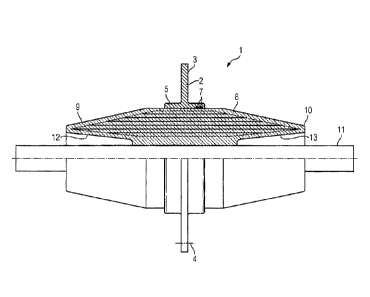
A high-voltage bushing for DC voltage in a gas-insulated, metal-encapsulated DC voltage switchgear assembly is provided with electrically conductive inserts. The novel high-voltage bushing is configured with a short, compact design, as it has at one or both ends, an inner conical cutout that opens towards the respective end.


French Abstract

Une traversée haute tension pour le courant continu dans un ensemble de commutation de courant continu encapsulé à enveloppe métallique, isolé par un gaz, est pourvue dinserts électroconducteurs. La nouvelle traversée haute tension est configurée avec une conception courte et compacte, à mesure quelle présente à lune ou les deux extrémités, une découpe conique interne qui souvre vers lextrémité respective.

Claims

Note: Claims are shown in the official language in which they were submitted.


81629475
CLAIMS:
1. A high-voltage bushing for DC voltage, the bushing comprising:
electrically conductive inserts extending between first and second ends;
the high-voltage bushing being formed, at least at one of said ends with
an inner conical cutout opening out towards said at least one end;
wherein the electrically conductive inserts are formed from concentric
conductive cylinders with different diameters and different lengths, starting
with a
relatively small diameter for a most exterior one of the conductive cylinders,

progressing to a largest diameter for an interior one of the conductive
cylinders, and
then progressing to another relatively small diameter for a most interior one
of the
conductive cylinders, the progressing from the largest diameter to the another

relatively small diameter resulting in said inner conical cutout; and
wherein reverse control is performed by means of the electrically
conductive inserts in the region of the inner conical cutout.
2. The high-voltage bushing according to claim 1, wherein said inner
conical cutout opens out towards said first end and the high-voltage bushing
is
formed with a further inner conical cutout at said second end and opening out
towards said second end.
3. The high-voltage bushing according to claim 2, which comprises a high-
voltage- conducting conductor extends centrally between said inner conical
cutout
at said first end and said further inner conical cutout at said second end.
4. The high-voltage bushing according to claim 1, wherein the high-
voltage bushing is disposed in a barrier plate of a gas-insulated, metal-
encapsulated DC voltage switchgear assembly.
- 6 -
Date Recue/Date Received 2020-05-12

81629475
5. The high-voltage bushing according to claim 1, which comprises
insulation consisting of resin-impregnataed paper.
6. In a gas-insulated, metal-encapsulated DC voltage switchgear
assembly, the high-voltage bushing according to claim 1 disposed in a barrier
plate of
the switchgear assembly.
- 7 -
Date Recue/Date Received 2020-05-12

Description

Note: Descriptions are shown in the official language in which they were submitted.


81629475
HIGH-VOLTAGE BUSHING FOR DC VOLTAGE
[0001]
BACKGROUND OF THE INVENTION
Field of the Invention:
[0002] The invention relates to a high-voltage bushing for DC voltage
with
electrically conductive inserts.
[0003] A high-voltage bushing of the generic type is known from Andreas
Kuchler, "Hochspannungstechnik", 2nd edition, 2005, pages 100 and 101. That
high-
voltage bushing is configured so as to be conically tapering at one of its
ends. A main
insulation body contains conductive grading layers, such as through an oil-
impregnated paper core containing metallic foils with different lengths,
continuously
increasing length in the axial direction from the outside to the inside.
SUMMARY OF THE INVENTION
[0004] It is accordingly an object of some embodiments of the invention
to
provide a pass-through bushing for a DC voltage which overcome various
disadvantages of the heretofore-known devices of this general type and which
provides for such a high-voltage bushing with a short, compact configuration.
- 1 -
Date Recue/Date Received 2020-05-12

CA 02808786 2013-03-07
54106-1334
[0005] With the foregoing and other objects in view there is provided, in
accordance with
some embodiments of the invention, a high-voltage lead-through bushing for DC
voltage.
The bushing comprising:
electrically conductive inserts extending between first and second ends
of the bushing; and,
the high-voltage bushing being formed, at least at one of the first and
second ends with an inner conical cutout opening out towards the at least one
end.
[0006] In other words, the object is achieved, in the case of a high-
voltage
bushing of the type specified at the outset, according to some embodiments of
the invention, with
a high-voltage bush having, at least at one end, an inner conical cutout which
opens
towards this end.
=
[0007] A primarily important advantage of the high-voltage bushing
according to
some embodiments of the invention is considered to be the fact that it is
considerably shortened
in length in comparison with the known high-voltage bushing because the region
within the
inner conical design is also utilized for voltage control. The high-voltage
bushing
according to some embodiments of the invention therefore has a comparatively
short
structural form in the axial direction.
[0008] In respect of its other end, the high-voltage bushing can be
designed
differently, depending on use; it is considered to be particularly
advantageous,
again for achieving a relatively short axial length, if the high-voltage
bushing has, at
its other end, a further inner conical cutout which opens towards this end.
- 2 -

CA 02808786 2013-03-07
54106-1334
[0009] The high-voltage bushing according to the invention can
be,configured
differently in respect of its high-voltage-conducting inner part. It appears
to be
advantageous if a high-voltage-conducting conductor extends centrally between
the
two inner conical cutouts.
[0010] Such an embodiment of the high-voltage bushing according to the
invention is particularly advantageous when the high-voltage bushing is
arranged in
a barrier plate of a gas-insulated, metal-encapsulated DC voltage switchgear
assembly because a gas-insulated metal-encapsulated DC voltage switchgear
assembly represents a compact switchgear assembly to the compact design of
which the high-voltage bushing according to the invention with this
configuration
advantageously contributes.
[0011] For the insulation of the high-voltage bushing, different
insulating
materials can be used; however, it is considered to be particularly
advantageous if
the insulation of the high-voltage bushing consists of resin-impregnated paper

because such a high-voltage bushing can be produced in a gas-tight manner.
Such
a bushing can be used in a barrier plate with particular advantage, in
particular for
gas-insulated switchgear assemblies.
[0012]
[0013] Although the invention is illustrated and described herein as
embodied in
a high-voltage bushing for DC voltage, it is nevertheless not intended to be
limited
- 3 -

81629475
to the details shown, since various modifications and structural changes may
be made
therein without departing from the scope of the invention and within the scope
and range
of equivalents of the claims.
[0013a] According to one aspect of the present invention, there is
provided a high-
voltage bushing for DC voltage, the bushing comprising: electrically
conductive inserts
extending between first and second ends; the high-voltage bushing being
formed, at
least at one of said ends with an inner conical cutout opening out towards
said at least
one end; wherein the electrically conductive inserts are formed from
concentric
conductive cylinders with different diameters and different lengths, starting
with a
relatively small diameter for a most exterior one of the conductive cylinders,
progressing
to a largest diameter for an interior one of the conductive cylinders, and
then progressing
to another relatively small diameter for a most interior one of the conductive
cylinders,
the progressing from the largest diameter to the another relatively small
diameter
resulting in said inner conical cutout; and wherein reverse control is
performed by means
of the electrically conductive inserts in the region of the inner conical
cutout.
[0013b] According to another aspect of the present invention, there is
provided in a
gas-insultated, metal-encapsulated DC voltage switchgear assembly, the high-
voltage
bushing as described herein disposed in a barrier plate of the switchgear
assembly.
[0014] The construction and method of operation of the invention,
however,
together with additional objects and advantages thereof will be best
understood from the
following description of a specific embodiment when read in connection with
the
accompanying drawing.
BRIEF DESCRIPTION OF THE DRAWING
[0015] The sole figure of the drawing is a partly sectional view of a
high-voltage
pass-through bushing according to an embodiment of the invention, in a barrier
plate of a
gas-insulated metal-encapsulated DC voltage switchgear assembly.
- 4 -
Date Recue/Date Received 2020-05-12

81629475
DETAILED DESCRIPTION OF THE INVENTION
[0016] Referring now to the figure of the drawing in detail, there is
shown a high-
voltage bushing 1 in a barrier plate 2 of a gas-insulated, metal-encapsulated
high-voltage
switchgear assembly. The latter is not further illustrated in order not to
complicate the
disclosure unnecessarily. The barrier plate 2 can be screwed to non-
illustrated flanges of
The metal encapsulation of the gas-insulated high-voltage switchgear assembly.
For that
purpose, the barrier plate 2 is formed with bores 3 and 4.
[0017] The high-voltage bushing 1 can be arranged so as to be sealed
by means
of sealing rings 7 within a ring-shaped attachment 5 of the barrier plate 2.
- 4a -
Date Recue/Date Received 2020-05-12

CA 02808786 2013-03-07
2012P04096
The high-voltage bushing 1 has electrically conductive inserts 8, which are
formed
from conductive cylinders with different diameters and different lengths.
[0018] As is also shown in the figure, the high-voltage bushing 1 is
provided with
an outer cone at in each case its one end 9 and its further end 10. The outer
cones,
however, do not reach as far as a high-voltage conducting conductor 11 of the
metal-encapsulating DC voltage switchgear assembly. The high-voltage bushing 1

has an inner conical cutout 12 at its one end 9 and a further conical cutout
13 at its
other end 10. The inner conical cutouts 12 and 13 each open out towards the
ends
9 and 10, respectively, of the high-voltage bushing 1. As a result of this, to
a certain
extent, reverse control is performed by means of the electrically conductive
inserts
8 in the region of the inner conical cutouts 12 and 13. This has the effect
that the
high-voltage bushing 1 is configured so as to be comparatively short in the
axial
direction.
[0019] The insulation of the high-voltage bushing 1 may be formed of
different
materials, for example casting compound, such as casting resin. In the
illustrated
embodiment, resin-impregnated paper is preferred for the insulation of the
high-
voltage bushing 1. This applies in particular to the use of the high-voltage
bushing 1
in gas-insulated switchgear assemblies because a high-voltage bushing 1 with
such insulation can be provided with the conductive inserts 8 in a relatively
simple
manner.
- 5 -
._

Representative Drawing
A single figure which represents the drawing illustrating the invention.
Administrative Status

For a clearer understanding of the status of the application/patent presented on this page, the site Disclaimer , as well as the definitions for Patent , Administrative Status , Maintenance Fee  and Payment History  should be consulted.

Administrative Status

Title Date
Forecasted Issue Date 2021-06-29
(22) Filed 2013-03-07
(41) Open to Public Inspection 2013-09-08
Examination Requested 2018-02-09
(45) Issued 2021-06-29

Abandonment History

There is no abandonment history.

Maintenance Fee

Last Payment of $263.14 was received on 2023-10-31


 Upcoming maintenance fee amounts

Description Date Amount
Next Payment if small entity fee 2025-03-07 $125.00
Next Payment if standard fee 2025-03-07 $347.00 if received in 2024
$362.27 if received in 2025

Note : If the full payment has not been received on or before the date indicated, a further fee may be required which may be one of the following

  • the reinstatement fee;
  • the late payment fee; or
  • additional fee to reverse deemed expiry.

Patent fees are adjusted on the 1st of January every year. The amounts above are the current amounts if received by December 31 of the current year.
Please refer to the CIPO Patent Fees web page to see all current fee amounts.

Payment History

Fee Type Anniversary Year Due Date Amount Paid Paid Date
Application Fee $400.00 2013-03-07
Maintenance Fee - Application - New Act 2 2015-03-09 $100.00 2015-02-04
Maintenance Fee - Application - New Act 3 2016-03-07 $100.00 2016-02-08
Maintenance Fee - Application - New Act 4 2017-03-07 $100.00 2017-02-14
Request for Examination $800.00 2018-02-09
Maintenance Fee - Application - New Act 5 2018-03-07 $200.00 2018-02-27
Maintenance Fee - Application - New Act 6 2019-03-07 $200.00 2019-02-06
Maintenance Fee - Application - New Act 7 2020-03-09 $200.00 2020-03-02
Maintenance Fee - Application - New Act 8 2021-03-08 $204.00 2021-02-26
Final Fee 2021-05-19 $306.00 2021-05-11
Maintenance Fee - Patent - New Act 9 2022-03-07 $203.59 2022-02-21
Registration of a document - section 124 $100.00 2023-01-25
Maintenance Fee - Patent - New Act 10 2023-03-07 $263.14 2023-02-27
Maintenance Fee - Patent - New Act 11 2024-03-07 $263.14 2023-10-31
Owners on Record

Note: Records showing the ownership history in alphabetical order.

Current Owners on Record
HSP HOCHSPANNUNGSGERATE GMBH
Past Owners on Record
SIEMENS AKTIENGESELLSCHAFT
SIEMENS ENERGY GLOBAL GMBH & CO. KG
Past Owners that do not appear in the "Owners on Record" listing will appear in other documentation within the application.
Documents

To view selected files, please enter reCAPTCHA code :


To view images, click a link in the Document Description column. To download the documents, select one or more checkboxes in the first column and then click the "Download Selected in PDF format (Zip Archive)" or the "Download Selected as Single PDF" button.

List of published and non-published patent-specific documents on the CPD .

If you have any difficulty accessing content, you can call the Client Service Centre at 1-866-997-1936 or send them an e-mail at CIPO Client Service Centre.


Document
Description 
Date
(yyyy-mm-dd) 
Number of pages   Size of Image (KB) 
Examiner Requisition 2020-04-03 4 228
Amendment 2020-05-12 15 565
Description 2020-05-12 6 194
Claims 2020-05-12 2 50
Final Fee 2021-05-11 5 120
Representative Drawing 2021-06-03 1 14
Cover Page 2021-06-03 1 40
Electronic Grant Certificate 2021-06-29 1 2,527
Abstract 2013-03-07 1 10
Description 2013-03-07 5 169
Claims 2013-03-07 2 32
Drawings 2013-03-07 1 19
Representative Drawing 2013-09-16 1 13
Cover Page 2013-09-16 1 37
Request for Examination 2018-02-09 2 69
Examiner Requisition 2018-12-12 5 287
Amendment 2019-01-15 6 193
Description 2019-01-15 6 178
Claims 2019-01-15 1 37
Prosecution Correspondence 2013-03-07 1 39
Examiner Requisition 2019-07-17 4 193
Amendment 2019-09-16 6 232
Assignment 2013-03-07 3 87
Drawings 2019-09-16 1 18
Description 2019-09-16 6 178
Correspondence 2015-01-15 2 64