Note: Descriptions are shown in the official language in which they were submitted.
WO 2012/024565 CA 02808800 2013-02-19PCT/US2011/048379
COMBINATION DRIVEN AND IDLER SNAP ROLLS FOR CORN HEADER
TECHNICAL FIELD
[001] This invention relates to cutting and gathering stalk crops such as corn
with a
header coupled to an agricultural vehicle.
BACKGROUND
[002] Agricultural harvesters such as combines are typically equipped with a
harvesting header. Corn headers are specifically designed to pick corn and
vary in size
from two-row units to twelve-row units or more. As the harvester moves through
the
field, each row-unit passes between rows of corn. Corn header row units
typically use
gathering chains to covey crop material and ears rearward toward a cross
auger. A set of
driven snap rolls, which rotate based on the speed of the harvester, grabs the
corn stalks
and forces them downward between stripper plates. The ears of corn are snapped
free of
the stalk and the cross auger passes the ears to the feeder housing of the
harvester. If the
snap rolls are operated too fast or too slow, ears of corn may be lost or
entire corn stalks
may be passed to the cross auger and feeder housing.
[003] Known row units require two gathering chains and two tensioners which
are
heavy, expensive and wear out easily. Furthermore, the gathering chains create
a
complicated drive mechanism because the axes of the drive sprockets driving
the chains
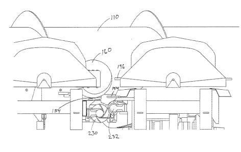
are at right angles to the axes of the snap rolls. Also, the gathering chains
do not
effectively convey a large mass of crop in conditions when material other than
ears of
corn, such as stalks and leaves, are severed from the ground. What is needed
is a simpler
and more cost effective row unit that is capable of conveying a large mass of
crop.
BRIEF DESCRIPTION OF THE DRAWINGS
[004] The accompanying drawings, which are incorporated in and constitute a
part
of this disclosure, illustrate various embodiments of the present invention.
In the
drawings:
[005] FIG. 1 shows a perspective view of a corn header having a plurality of
row
units for an agricultural vehicle;
1
WO 2012/024565 CA 02808800 2013-02-19 PCT/US2011/048379
[006] FIG. 2 shows a top view of the header of FIG.1;
[007] FIG. 3 shows a close-up view of a portion of the header of FIG. 1;
[008] FIG. 4 shows a portion of the bottom of the header of FIG. 1;
[009] FIG. 5 shows a close-up view of a portion of the bottom of the header of
FIG.
1;
[010] FIG. 6 shows a perspective view of a frame which forms part of a live
row
unit and part of an adjacent dead row unit;
[011] FIG. 7 is a close-up front view of the header showing offset stripper
plates and
a powered snap roll and an unpowered idler roll offset from one another;
[012] FIG. 8 is a close-up front view of the header showing offset stripper
plates and
a pair unpowered idler rolls offset from a powered snap roll;
[013] FIG. 9 shows offset stripper plates and offset snap rolls;
[014] FIG. 10 shows offset stripper plates and a powered snap role and an
idler roll
offset from one another;
[015] FIG. 11 shows offset stripper plates and a pair of idler rolls offset
from a
powered snap roll; and
[016] FIG. 12 shows offset stripper plates and a powered snap roll offset from
an
idler roll.
DESCRIPTION OF EXAMPLE EMBODIMENTS
[017] The present invention is susceptible of embodiment in many different
forms.
While the drawings illustrate and the specification describes certain
preferred
embodiments of the invention, it is to be understood that such disclosure is
by way of
example only. There is no intent to limit the principles of the present
invention to the
particular disclosed embodiments. References hereinafter made to certain
directions,
such as, for example, "left" and "right", are made as viewed from the front
looking
rearward.
2
CA 02808800 2013-02-19
WO 2012/024565 PCT/US2011/048379
[018] The exemplary header 100 selected for illustration in FIGS. 1-5 has a
cross
auger 110 with spiral fighting 112 for sweeping the ears of corn toward the
center of the
header 100. Large cross augers 110 may also have paddles 130, fingers 132 or
some
other means to facilitate the delivery of the crop rearward to the feeder
housing of a
harvester. The header 110 has a plurality of forward-extending live row-units
120 and a
plurality of forward-extending dead row units 124. The row units 120, 124 and
the cross
auger 110 define a feeder plane therebetween where useable parts of stalk
crops are
conveyed rearward from the row units 120, 124 to the cross auger 110.
[019] Live row units 120 and dead row units 124 cooperate with one another.
Live
row units 120 have powered components, as described in greater detail below,
whereas
the dead row units 124 generally do not have powered components. In one
embodiment,
as best shown in FIGS. 1 and 2, the header 110 has four live row units 120,
three dead
row units 124, plus one half of a dead row unit 130 on each end of the header
110. The
row units 120, 124 are arranged relative to one another so that the row units
120, 124
alternate relative to each other along the length of the header 110. In other
words, every
other row unit is a live row unit 120 with a dead row unit 124 adjacent to
each live row
unit 120. The row units 120, 124 are spaced relative to one another to
correspond with
the spacing of the crop to be harvested and to provide a path to receive the
crop
therebetween. For example, a live row unit 120 may be placed between two dead
row
units 124 to cooperate therewith.
[020] FIG. 6 illustrates a row assembly 138 having a frame 140, a back end 142
and
a forward end 144. Half of the frame 140 forms part of a live row unit 120 and
the other
half forms part of a dead row unit 124. Therefore, one live row unit 120
includes two
halves of two separate and adjacent frames 140. One dead row unit 124 includes
two
halves of two separate and adjacent frames. Each frame 140 includes a first
portion 146
and a second portion 148 which are spaced from one another and protrude
outwardly and
forward from the back end 142. At the front and between adjacent row units
120, 124 is
a crop entry 150 for receiving the stalks of the crop. The first and second
portions
146,148 receive stripper plates 154 which cooperate with one another to define
the crop
3
WO 2012/024565 CA 02808800
2013-02-19
PCT/US2011/048379
passage 156 between adjacent row units 120, 124. The stripper plates 154 strip
useable
parts such as ears of corn from crop stalks that are received in the crop
passage 156.
[021] Each live row unit 120 of the present invention
includes at least one fore-to-
aft gathering auger 160, in place of the two gathering chains and tensioners,
for
conveying the useable parts rearward to the cross auger 110. Each gathering
auger 160
has a proximal end and a distal end and is preferably aligned substantially
with a
corresponding crop passage 156. However, the axis of rotation of the gathering
auger
160 may instead be misaligned with the crop passage 156 such that the crop
stalks in the
back of the crop passage may be urged more so toward the gathering auger 160
than the
crop stalks are at the beginning of the crop passage 156.
[022] Preferably, each live row unit 120 includes a pair of
counter-rotating augers
160. The dead row units 124, on the other hand, do not include gathering
augers 160 or
any gathering chains. Therefore, the complexity of the header 110 is reduced
by utilizing
gathering augers 160 on live row units 120 instead of gathering chains and
tensioners.
Also, by utilizing dead row units 124 in combination with the live row units
120 the
overall complexity of the header 110 is substantially reduced because the dead
row units
124 do not have gathering augers 160 or gathering chains and tensions and also
because
the drive means for driving the gathering augers 160 is simpler than known
drives used in
combination with gathering chains.
[023] The gathering augers 160 are preferably driven
independently of the snap
rolls. The gathering auger 160 may be driven by electrical, mechanical or
hydraulic
means. Preferably, each gathering auger 160 is cantilevered from the frames
140 and
rotationally driven from the forward most end of its respective row unit 120
away from
the cross auger 110 rather than the rear of the row unit 120 in close
proximity to the cross
auger 110 so that the delivery or the distal end of the gathering auger 160 is
not
obstructed. This allows ears and stalks to be delivered to the cross auger 110
unimpeded
by bearing supports, drive mechanisms or some other crop impeding structure.
[024] In one or more embodiments of the present invention,
the proximal end of one
or more gathering augers 160 is coupled to the frame 140 of the row unit 120
in a manner
that permits the distal end of the gathering auger 160 to move into and out of
the feeder4
CA 02808800 2013-02-19
WO 2012/024565 PCT/US2011/048379
plane. In one embodiment, a mechanism coupled to the proximal end of the
gathering
auger 160 allows the gathering auger 160 to rotate or pivot in a vertical
plane between a
first position for processing crops when harvesting and a second position for
maintenance
purposes. Preferably, the distal end of the gathering auger when in the first
position is
higher in the vertical plane than when the distal end is in the second
position.
[025] Also, the gathering auger 160 preferably pivots partially about a
substantially
horizontal rotational axis that extends substantially transversely between the
row units
120. The gathering auger 160 may be pivoted such that its distal end is raised
upward
above the row unit 120 to allow the gathering auger 160 to be repaired,
replaced or
perform maintenance without interference from the cross auger 110. Also, when
the
gathering auger 160 is pivoted upward out of the feeder plane other components
can be
more easily accessed.
[026] An arrangement of gears or wheels such as bevel gears 182, 184 may be
used
for transmission of the driving motion to the gathering auger 160 from a
driven shaft 166
within each live row unit 120 while also allowing the distal end of the
gathering auger
160 to pivot upward about the same axis of the shaft 166. Each shaft 166
preferably
drives a pair of gathering augers 160 of a single live row unit 120 so that
the pair of
gathering augers are driven about the same axis about which they may pivot
into and out
of the feeder plane. When the gathering auger 160 is pivoted upward, fasteners
may be
removed from the auger 160 so that the outer fighting portion of the gathering
auger 160
may slide rearward so that it may be removed from an inner shaft and from
cylindrical
bearings allowing the fighting portion to rotate about the inner shaft.
[027] A mounting bracket 210 rotationally couples the gathering auger 160 to
an
outer side of the frame 140 of the row assembly 138, such as vertical mounting
support
220, to secure the gathering auger 160 to the frame 140 in an operational
manner. The
vertical mounting support 220 includes radial extending openings or arched
slots 224 for
receiving fasteners 226 for securing the mounting bracket 210 to the frame
140. When
the distal end of the gathering auger 160 is pivoted upward, the distal end of
the gathering
auger 160 coupled to the mounting bracket 210 causes the mounting bracket 210
to rotate
in the slots 224 of the vertical mounting support 220. The length of the
arched slots 224
5
CA 02808800 2013-02-19
WO 2012/024565 PCT/US2011/048379
dictate the range the gathering auger 160 can be pivoted between the first and
second
positions. The range of motion of the distal end of the gathering auger 160
may be
limited by the length or shape of the slots 224.
[028] The pair of straight bevel gears 182, 184, in mesh are used to drive the
gathering auger 160 while harvesting. The shaft 166 of the live row unit 120
corresponds
with the axis upon which one or more augers 160 pivot. The distal end of the
gathering
auger 160 is coupled to the bevel gear 182 which is driven by the bevel gear
184 on shaft
166. The shaft 166 may be chain driven by a hydraulic drive motor 178 with
sprocket
180. Preferably, the drive motor 178 is sufficiently sized to drive all of the
gathering
augers 160. The drive motor 178 and sprocket 180 with chain 198 drives
sprocket 188
and shaft 186 which extends in a transverse manner along the length of the
header 100.
There are preferably numerous other sprockets 188 along the length of the
shaft 186. The
number of sprockets 188 depends on the number of live row units 120. Chains
190
extend from the sprockets 188 of the shaft 186 to sprockets 192 on shaft 166.
[029] Because the augers 160 are driven by the drive motor 178, the speed of
the
augers 160 is independent of the speed of the cross auger 110. The chain 190
driving the
sprocket 192 which in turn drives the shaft 166 with bevel gears 182. The
speed of the
augers 160 can be changed automatically or manually in relation to the ground
speed
much like current grain headers on harvesters that control reel speed.
Moreover, the
augers 160 can be driven independent of the snap rolls. The speed of the
gathering
augers 160 may be varied while either or both the harvester and the snap rolls
are
maintained at a constant speed.
[030] In addition to the apparatuses described herein, the inventions include
a
method for harvesting crop with an attachment for an agricultural vehicle that
includes
the gathering augers 160. The method includes operating the gathering augers
160 at a
first speed to gather crop stalks in the crop passages 156 and operating a
snap roll for
removing useable parts from crop stalks at a second speed independently of the
gathering
augers 160. The method may also include one or more of the following steps:
varying
the speed of the gathering augers 160 while the speed of the snap rolls remain
constant,
increasing the speed of the gathering augers 160 while the speed of the snap
rolls remain
6
WO 2012/024565 CA 02808800 2013-02-19 PCT/US2011/048379
constant, decreasing the speed of the gathering augers 160 while the speed of
the snap
rolls remain constant, varying the speed of the snap rolls while the speed of
the gathering
augers 160 remain constant, increasing the speed of the snap rolls while the
speed of the
gathering augers 160 remain constant, decreasing the speed of the snap rolls
while the
speed of the gathering augers 160 remain constant, and/or changing the speed
of the
gathering augers 160 relative the ground speed of the harvester.
[031] To keep stalks captured and engaged by the gathering auger 160 an
elongated
member 196 such as a rod is positioned in close proximity to the fighting of
the
gathering auger 160. Preferably, the elongated member 196 is substantially
parallel
aligned with the gathering auger 160. However, in other embodiments, at least
a portion
of the elongated member 196 may be shaped or curved along its length or the
distal end
of the elongated member 196 may be closer in proximity to the distal end of
the gathering
auger 160. The elongated member 196 may be rigid, flexible, or semi-flexible
to urge the
stalks in the crop passage toward the gathering auger 160. In one or more
embodiments,
the elongated member 196 is cantilevered off the forward end 144 of the frame
136 of the
dead row unit 124 to urge the stalks in the crop passage 156 toward the
gathering auger
160 of the opposing live row unit 120. The dead row unit may also include a
second
elongated member 196 extending toward another gathering auger 160 of another
live row
unit. In an alternative embodiment, the elongated member 196 may be a strap or
be
detachably coupled or mounted to a row unit.
[032] Underneath the stripper plates 154 of each frame 140 are one or more
snap
rolls. At each crop passage 156 there is one driven snap roll 230 on one side
of the crop
passage 156 and one or more undriven idler rolls 232 opposing the snap roll
230 from the
other side of the crop passage 156. Angled bearing supports may be used to
mount the
snap rolls and idler rolls to the frames.
[033] Because the idler rolls 232 are undriven, the powered snap roll 230 is
operated
at different speeds relative to the idler rolls 232. Preferably, the powered
snap roll 230
opposes a pair of idler rolls 232. On each side of a live row unit 120 there
is a driven
snap roll 230 and on each side of a dead row unit 124 there is at least one
idler roll 232.
Preferably, each side of the dead row unit 124 includes two idler rolls 232
for a total of
7
CA 02808800 2013-02-19
WO 2012/024565 PCT/US2011/048379
four idler rolls 232 for each dead row unit 124. Unpowered idler rolls 232
preferably
have smooth outer peripheries without knives or bars and are lighter and less
expensive
which helps to conserve power that could instead be used to chop stalks with
mowers as
described below.
[034] Preferably, the powered snap rolls 230 include knives 234. If the idler
roll
232 where to be powered it could be powered at a slower speed than an opposing
snap
roll 230. Also, the idler roll 232 could be adjustable relative to the side of
the frame 136
of a dead row unit 124 so that it could be moved closer to the snap roll 230
for stalk
chopping or moved away when reduced stalk chopping is desired.
[035] One or both ends of the idler roll 232 could also be spring loaded to
allow it
to move away if an obstruction is encountered in the crop passage 156. The
angle
bearing could incorporate a spring or a spring could be used at the opposite
end to bias
the idler roll toward the crop stalks and the opposing snap roll but then also
allow an
obstruction to pass between the opposing idler and snap rolls by compressing
the springs.
[036] The inventions also include a method for harvesting stalk crops with an
attachment for an agricultural vehicle. The method includes pulling crop
stalks in a crop
passage with a snap roll against at least one stripper plate. The method also
includes
biasing the snap roll toward the crop stalks in the crop passage and allowing
the snap roll
to move laterally in the event of an obstruction in the crop passage impacting
the snap
roll. The movement of the snap roll allows the obstruction to pass.
[037] A single idler roll 232 is preferably offset from its opposing snap roll
230 in
that the snap roll 230 and idler roll 232 are at different heights or
different distances from
the ground so that the corn plant is not pulled straight down or in other
words is pulled
down at other than a perpendicular angle to the ground. If utilizing a pair of
idler rolls
232 to oppose the snap roll 230, upper and lower idler rolls 232 are
positioned so that the
axis of rotation of the driven roll 230 is vertically between but horizontally
offset from
the axis of rotation of each idler roll 232. The axes of rotation of both
idler rolls 232 are
preferably both parallel and vertically aligned with each other because the
idler rolls 232
are at different distances from the ground relative to each other.
8
WO 2012/024565 CA 02808800 2013-02-19 PCT/US2011/048379
[038] One or more idler rolls 232 vertically offset from their opposing and
corresponding snap roll 230 helps to lean or urge the corn plant toward the
gathering
auger 160 which is positioned on one side of a live row unit 120. Also, in one
or more
embodiments, the stripper or deck plates 154 may also be offset from one
another relative
to the ground to urge the crop to the side of the crop passage 156 with the
gathering auger
160. Improved cutting action is achieved by running the knives 234, also
commonly
referred to as flutes or bars, of the powered snap rolls 230 in close
proximity to the one or
more opposing idler rolls 232. A pair of idler rolls 232 cooperating with one
another to
oppose a snap roll 230 further increase the cutting and chopping ability by
enhancing the
engagement of the stalks in the knives 234 of the snap roll 230.
[039] The foregoing has broadly outlined some of the more pertinent aspects
and
features of the present invention. These should be construed to be merely
illustrative of
some of the more prominent features and applications of the invention. Other
beneficial
results can be obtained by applying the disclosed information in a different
manner or by
modifying the disclosed embodiments. Accordingly, other aspects and a more
comprehensive understanding of the invention may be obtained by referring to
the
detailed description of the exemplary embodiments taken in conjunction with
the
accompanying drawings, in addition to the scope of the invention defined by
the claims.
9