Note: Descriptions are shown in the official language in which they were submitted.
CA 02808879 2013-02-20
WO 2012/041268 PCT/DE2011/001641
Apparatus and method for operating a flight simulator
with a special impression of reality
The invention relates to a method and an apparatus for
operating a flight simulator with a special impression
of reality.
DE 10 2008 023 955 B4 describes a method for simulating
events and processes of aircraft, land vehicles or
watercraft and a simulation system. This invention is
based on the object of actuating a simulation device in
real time even though the data which is necessary for
actuation is made available merely by a non-real-time
simulation program, wherein a latency time which is
caused by a data manager is to be compensated.
In this context, the time which is actually required by
processes in the real world is understood to be the
real time. The term real time does not mean a specific
speed or processing power of the program or of the
controller but instead defines only the time frame
within which the system must react. The term latency
time means a time period between an action and the
occurrence of the expected reaction, that is to say a
delay time. In this patent, protection is essentially
given to the fact that if data is not received in good
time the data gap which occurs is replaced by data from
empirical values or data from preceding simulation
programs and this data is then transmitted to the
movement controller of the real time simulation device
[0046]. Details on the specific improvement of the
mechanical configuration of a flight simulator are not
available here.
DE 600 20 466 T2 describes what is referred to as a
parallel robot with four degrees of freedom which
solves the problem of shifting a movable plate with
four degrees of freedom at high speed and with a high
REPLACEMENT SHEET (RULE 26)
CA 02808879 2013-02-20
WO 2012/041268 - 2 - PCT/DE2011/001641
acceleration and of positioning the moveable plate with
a high degree of rigidity and accuracy. The term
parallel robot is used here to refer to a robot in
which a multiplicity of actuators are arranged in
parallel, wherein such a robot can be applied, for
example, in a travel simulator for a motor vehicle.
With respect to the prior art, this document specifies
parallel robots which have six degrees of freedom and
which are used, for example, in flight simulators such
as are disclosed in US 5 333 514 and US 5 715 729. In
order to solve the problem proposed in DE 600 20 466
T2, a parallel robot is described which is composed
essentially of a specific arrangement of a parallel
linkage (3), a moving platform (4), coupling parts (42)
and kinematic elements (33). A particular application
of such a robot in a flight simulator is not mentioned
here.
WO 96/26 512 A (translation of the corresponding
European patent available as DE 696 23 410 T2)
discloses an improved flight simulator which is based
on the problem of more precisely simulating the real
movement which a pilot senses when maneuvering an
aircraft. This is based on a movement simulator having
a supporting device (102) and a pitching movement strut
(114) with a pitching movement axis, wherein the pitch-
ing movement strut (114) is rotatably connected to the
support device, and wherein the movement simulator
comprises the following:
a rolling movement strut (134) with a rolling
movement axis which is perpendicular to the pitch-
ing movement axis and is rotatably connected to
the pitching movement strut (114), and a partici-
pant cabin (160) having a center of gravity,
wherein the participant cabin (160) is held by the
rolling movement strut in such a way that the
center of gravity of the participant cabin is
separated from the pitching movement axis.
CA 02808879 2013-02-20
WO 2012/041268 - 3 - PCT/DE2011/001641
In order to solve the above problem, in the case of
this flight simulator protection was given to the fact
that the rolling movement strut (134) is rotatably
connected to the pitching movement strut (114) in such
a way that the rolling movement strut (134) can rotate
completely about the pitching movement strut (114) in a
plane perpendicular to the pitching movement axis.
Apart from the fact that this feature only contains
details which relate to an effect to be achieved,
without details on the specific embodiment, the flight
simulator described here appears worthy of improvement.
The apparatus according to the invention and the
corresponding method are therefore based on the object
of presenting an apparatus and a method with which the
operation of a simulator can be achieved with a special
impression of reality for learning how to control a
vehicle, in particular an aircraft, moving in three-
dimensional reality. In addition, for the instructor
who is accompanying the learning process there is also
to be the possibility of being able to monitor
objectively the learning progress and the degree of
loading of a trainee.
This object is achieved with an apparatus as claimed in
claim 1 and a method as claimed in claim 6.
The apparatus according to the invention will be
described in more detail below. In particular, in this
context, in the drawing:
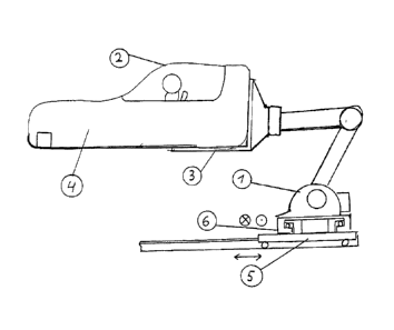
Fig. 1 shows a side view of a simulator
according to the invention,
Fig. 2 shows a side view of the projection
conditions, and
Fig. 3 shows a representation of the imple-
mented additional simulation devices and
CA 02808879 2013-02-20
WO 2012/041268 - 4 - PCT/DE2011/001641
systems for detecting the human
reactions.
The underlying idea of the present invention is, on the
one hand, to simulate, by means of a special 6-axis
robot which can be moved in two dimensions, the
conditions in a vehicle cabin, specifically of an
aircraft, such as actually occur in reality. On the
other hand, the trainee is to be provided with a real
simulation of the expected difficulties by means of a
realistic representation of the surroundings which are
to be expected during operation. The instructor is, in
turn, to be supplied all the time with a realistic
impression of the physical and psychic loading and/or
the load-bearing capability of a trainee by means of
data representing the physical state of the trainee.
The side view of a simulator according to the invention
shown in fig. 1 makes the main novelties of the
inventive concept apparent. A 6-axis robot 1 is, on the
one hand, connected here directly via an adaptor plate
3 to a vehicle cockpit 4, to the entry 2 and, on the
other hand, securely to a device 6 for translatory
lateral movement. The lateral movements which are
possible with this device 6 are characterized by means
of the customary arrow symbols. The travel movements of
a device 5 for translatory longitudinal movement, on
which device 5 the device 6 is installed, are
illustrated by means of the double arrow shown. This
combination of the devices 6 and 5 permits accelerated
movements of the aircraft cabin 4 in the longitudinal
direction and in the lateral direction simultaneously,
independently of the movements of the robot 1. The
longitudinal direction is defined here by the longitu-
dinal orientation of the aircraft, that is to say of
the aircraft cabin 4. Since the simulation of the
conditions in an aircraft such as, for example, a
passenger plane, is expected to involve the greatest
CA 02808879 2013-02-20
WO 2012/041268 - 5 - PCT/DE2011/001641
demands being made of the simulator, this case will be
considered in more detail below.
The center of gravity of a passenger plane, or of any
other aircraft with aerofoils, is approximately in the
region of the center of these aerofoils. The center of
gravity is the point at which the entire weight of such
an aircraft can be imagined as being combined and about
which the entire plane can, as it were, rotate.
However, the pilot's seat is generally located at a
distance from the center of gravity of the plane, both
shifted forward in the direction of flight and moved
upward in relation to the center of gravity of the
plane. This means that, for example when a plane
starts, the pilot not only experiences the normal move-
ment of the center of gravity of his plane but also
experiences an additional torque which arises substan-
tially from the distance between the pilot's seat and
the center of gravity of the plane.
In the example of fig. 1, this corresponds approxi-
mately to the distance between the center of the device
5 for a translatory longitudinal movement and the seat
4 in the aircraft cockpit of the flight simulator.
Therefore, in order to simulate a starting process it
is possible with the simulator according to the
invention to move the vehicle cockpit 4 in the longitu-
dinal direction by means of the device 5 for transla-
tory longitudinal movement. The 6-axis robot 1 carries
out the normal combined lifting movement and pivoting
movement of a starting vehicle here. For this purposes,
the device 5 can be moved with natural acceleration in
the translatory mode. As a result of the fact that the
device 6 for translatory lateral movement is movably
installed on the device 5 for translatory longitudinal
movement, combined accelerated movements of the two
devices are possible both individually and jointly.
In order to use the device 6 for translatory lateral
movement, reference is made to the following example:
CA 02808879 2013-02-20
WO 2012/041268 - 6 - PCT/DE2011/001641
If in this case of a normal starting process it is also
to be stimulated that during the starting process the
aircraft is affected by shearing winds, a hazardous
form of side winds, this can be simulated in conditions
close to reality by means of the additional use of the
device 6 for translatory lateral movement. In this
context it is self-evident that such a simulation by
means of the devices 5 and 6 for translatory
longitudinal movement and respectively for translatory
lateral movement can only take place for as long as the
travel path of the respective device is configured.
However, in practice the travel path of the device 5
for translatory longitudinal movement is made longer
than that of the device 6 for translatory lateral
movement. This also corresponds to the real
requirements here since shearing winds usually occur
briefly and in the manner of gusts.
In particular the unexpected occurrence of shearing
winds when aircraft start or land easily gives rise to
accidents and it is to be simulated by means of the
inventive simulator in conditions close to reality.
Fig. 2 outlines in a side view the projection
conditions of the simulated external view in the
vehicle cockpit 4.
The reference 15 represents here a possible OLED view
which can be adapted, as a flexible screen, to the
contours of the respective vehicle cockpit 4. OLED
stands here for "organic light emitting diode" and
denotes a low-viscosity illuminating component made of
organic semi-conducting materials which differs from
the inorganic light-emitting diodes in that, on the one
hand, the power density and the lighting density are
lower and, on the other hand, no monocrystalline
materials are necessary. The OLED technology is
excellently well suited for screens and displays. A
further field of use is large-area spatial illumina-
tion.
CA 02808879 2013-02-20
WO 2012/041268 - 7 - PCT/DE2011/001641
An alternative possible way of representing the
simulated external view is that this external view is
projected by means of projectors onto projection
surfaces which are located outside the vehicle cockpit
4.
See in this respect:
http://en.wikipedia.orgNiki/Cave Automatic Virtual Environm
ent. In the side view shown, the projection surface 9
of the front portion, the projection surface 8 of the
right-hand side portion and the projection surface 7 of
the ceiling portion can be seen in this case. These
projection surfaces can be connected to the vehicle
cabin 4 or installed in the simulation space. In the
latter case, these projection surfaces must, of course,
be correspondingly large in the spatial dimensions.
There are suitable projection methods for this purpose
which permit a scene to be represented with a depth
character on straight, abutting projection surfaces
with joint edges which run in a linear fashion, wherein
these joint edges which run in a linear fashion can be
made invisible for representing a total image with
relatively low computational complexity. This making
invisible is carried out by means of "calculating out"
by computer the relatively precisely defined abutment
edges of the projection areas used.
For the use of the flight simulator according to the
invention for training helicopter pilots, it is also
possible in one particular refinement to provide a
further projection surface which maps the ground area.
In this case, the aircraft cockpit 4 is equipped with
an additional transparent floor panel.
Fig. 3 shows a representation of the implemented
additional simulation devices and systems for detecting
the human reactions. For this purpose of simulating a
fire which has broken out onboard, a central smoke
generator 12 is provided with a controllable smoke
distribution 11. With this system it is possible for
CA 02808879 2013-02-20
WO 2012/041268 - 8 - PCT/DE2011/001641
the operator of the simulation system to produce smoke
of a defined type and intensity at certain locations of
the aircraft cockpit 4 which are important for
practical use. In addition, in a particular form of the
embodiment it is possible to subject the entire vehicle
cockpit 4, in a defined way which occurs under
practical everyday conditions, to shaking movements
such as are caused, for example, by propulsion unit
damage which is becoming apparent. In order to be able
to simulate the occurrence of such damage situations in
even more realistic fashion, in this embodiment
additional acoustic backgrounds are also provided to
the flight trainee by means of a complex loudspeaker
system. For reasons of clarity, corresponding devices
have not been represented separately. The system 14 for
illuminating the cabin can be changed in a directly
controlled manner or in a programmed manner with
respect to the color and the intensity (flickering
light) in accordance with the simulated realities.
The reactions of a flight trainee can be detected with
the detector device 16 for detecting a movement of
persons and/or for detecting the physiognomy and/or
recorded for later evaluation of the human reactions
(maneuver criticism).
The measuring device 10 for measuring the resistance of
the skin of a flight trainee serves a comparable
purpose. The resistance of the skin can be most easily
measured in the region of the control knob or some
other control unit. The surface of an emergency switch,
which is possibly present, is also suitable for this
purpose.
The sensor 17 serves to detect the actually realised
movements of the vehicle cockpit 4. The output signals
of the sensor 17 serve to record the entire profile of
a training unit of the respectively operated simulation
program.
CA 02808879 2013-02-20
WO 2012/041268 - 9 - PCT/DE2011/001641
The operator control panel used can be quickly adapted
to the respectively simulated aircraft type or vehicle
type by means of the module system 13 using easy-to-
exchange slide-units.
It is apparent that the flight simulator according to
the invention is also suitable for use in military
projects since a considerable experience potential of a
fighter pilot is important particularly in this area
for the purposes of preparing for hazardous deployment.
Such experience potential can be obtained cost-
effectively by training with a flight simulator with a
special impression of reality without endangering human
lives.
The control of the complex movement processes and the
signal processing of the sensors used requires a
special control program.
1
CA 02808879 2013-02-20
WO 2012/041268 - 10 - PCT/DE2011/001641
List of reference numbers
1 6-Axis robot
2 Entry
3 Adaptor plate
4 Vehicle cockpit, aircraft cockpit
5 Device for translatory longitudinal movement
6 Device for translatory lateral movement
7 Projection surface of the ceiling portion
8 Projection surface of the right-hand side
portion
9 Projection surface of the front portion
10 Measuring device for measuring the resistance
of the skin
11 Smoke distribution
12 Smoke producer
13 Module system for changing over the operator
control panel
14 System for illuminating the cabin
15 OLED display
16 Detector device for detecting movement of
persons and/or for detecting the physiognomy
17 Sensor for detecting the cockpit movement