Note: Descriptions are shown in the official language in which they were submitted.
CA 02808960 2013-02-20
SELF-ALIGNING SOCKET FOR MOORING CABLE
The present invention relates to the field of mooring cables, in particular
those used in the maritime environment. It relates more specifically to an end
socket for cables of mooring lines, especially of the offshore mooring
catenary
type for anchoring massive floating elements systems for oil and gas
production
at sea, albeit without being limited thereto.
In the field of what is known as "offshore" oil and gas production in the
marine environment along coasts, mooring cables, also referred to as
catenaries, serving for tethering with very high tensile capacity, are used
for
anchoring massive floating elements such as offshore platforms, loading buoys
or even submerged stages of column systems ascending to the surface (SPAR,
riser tower system).
The mooring cables, often disposed in anchoring systems converging at
the level of the mobile massive floating element to be anchored, are connected
by their end sockets (which may or may not be associated with connection
pieces) on the one hand to a fixed device anchored on the sea floor and on the
other hand to the floating element to be anchored.
It is recalled that such mooring lines may have lengths in excess of one
kilometer. Furthermore, this reference length will undoubtedly be increased in
the coming years, since undersea prospecting is spreading to progressively
deeper waters.
Consequently, the diverse connections and components of the anchoring
system at each end of such mooring lines must be able to resist the
considerable repetitive strains and forces generated by waves, by marine
currents, by winds or even by the different operating stresses of the offshore
installation itself. An offshore mooring catenary line actually participates
in the
movements of waves, so that fatigue strength in particular becomes a
CA 02808960 2013-02-20
2
substantial requirement, both in tension and in bending, especially where the
cable exits its end socket.
Traditional mooring lines equipped with end sockets of clevis, bail or
even eye type are known. Such a socket consists mainly of a hollow body of
frustoconical general shape forming a fastening receptacle and having, at its
broadest end, ears (or a web) pierced by a bore intended to receive a
connection shaft or an oval bail intended for the connection with the system
to
be anchored. By virtue of its undercut shape, the fastening receptacle has a
blocking function and for this purpose receives an end of the mooring cable
wherein the strands first have been spread out in sheaf form, before being
filled
with a cast material which, after solidification, makes the cable and the
socket =
irreversibly Integral.
Within the different anchoring systems, of overhead type but more
particularly are underwater, the mooring lines are subjected to cycles of
alternating tensions or repeated bending due to the stresses undergone by the
mobile element to be anchored and to the resulting movements. The anchoring
systems and the cable-based mooring lines constituting them must then be
designed and produced in a manner that takes the conditions of use into
account. It is necessary in particular to avoid any concentration of repeated
bending stresses at the level of the portion of the mooring cable situated
precisely at the outlet of its end socket. =
As already indicated in the foregoing, with a view to connecting them to
the mobile element to be anchored or to the end-of-line anchors, the end
sockets of the cables with which the present anchoring systems are equipped
comprise externally, on the side opposite the cable entry, coupling means that
assure pivoting fixation of the socket on the element to be anchored, In this
way
there is accomplished a pivoting coupling which, under the action of the
different stresses to which the anchoring system is subjected, permits
alternating rotational movements of the socket around an axis orthogonal to
its
CA 02808960 2014-09-04
3
own longitudinal axis. With this type of socket, however, it will be noted
that the
cable freely exits the socket, precisely at the foot of the expanded sheaf of
strands retained in the fastening receptacle, or at a relatively short
distance
therefrom. Now, by virtue of the torque effect, the weight of the socket is
largely
sufficient for it to follow the partial rotational movements around its
pivoting axis,
thus imposing parasitic bending stresses on the cable portion situated at the
outlet of the fastening receptacle.
A known solution for overcoming this disadvantage is to limit the parasitic
bending stresses induced In the cable at the socket outlet by protecting it
with a
stiffener.
= The installation of such an equipment item Is all the more important in
view of the fact that the rigidity of the cable in bending will become
smaller, or
that materials of higher quality will be used to construct it, as in the case
of
modern high-strength steel cables or else mixed cables made from steel wires
and synthetic materials, or even from purely synthetic materials.
Such a stiffener, intended to permit the socket to self-align with its cable,
typically has the form of a sleeve installed around the cable at the socket
outlet,
the rigidity and thickness of which sleeve decrease progressively with
Increasing distance therefrom. The stiffener, generally made of plastic
material
of adapted rigidity and consistency, in this way has increasing flexibility
from its
large base to its tip, thus making It possible to reduce, but only reduce, the
risks, sometimes severe, of parasitic bending of the cable at the outlet of
its end
socket.
The present Invention has precisely the main objective of proposing a
new type of self-aligning end socket for cables of mooring lines constituting
anchoring systems susceptible to being subjected to large cyclic variations of
geometry and stresses in the course of their use.
In one aspect, the present invention relates to a self-aligning socket
CA 02808960 2013-02-20
4
intended to be mounted at the end of a mooring cable for an anchoring system
of a mobile massive element, the socket comprising:
- a socket body having an internal cavity comprising a guide chamber for
the mooring cable, an intermediate section and a fastening receptacle
intended to receive and block the ends of the strands of the mooring
cable, and
- means for coupling with the mobile massive element to be anchored,
positioned on the socket body in such a manner as to define a pivoting
axis of the socket body, which axis passes through the intermediate
section of the socket.
Thus it is understood that the employment of the invention has as a first
effect forcing the socket to be retained continuously in line with the cable
carrying it. This result is due mainly to the presence of a cable-guide
chamber
in the very body of the socket, which chamber actually functions as an
internal
stiffener by virtue of its internal wall, which comes into contact with the
cable in
the manner of a retaining envelope.
In addition, a retaining sleeve of shape complementary to the guide
chamber may be inserted therein to receive the mooring cable. For practical
reasons of adaptability of the socket to the different possible diameters of
the
cable, it is understood that it will be advantageous to provide a guide
chamber
broader than the cable to be guided, so that such a dimensioned retaining
sleeve, of shape adaptable according to the needs, can be inserted therein.
In a preferred embodiment, the center of gravity G of the socket is
located at the intermediate section and therefore in proximity to its pivoting
axis,
even on this pivoting axis or else between the pivoting axis and the start of
the
guide chamber. The pivoting axis of the socket relative to the elements to
which
it is connected is therefore located in immediate proximity to the point of
CA 02808960 2014-09-04
application, on the socket, of the tensile forces transmitted by the cable
during
its use within the anchoring system. In this way it is possible to avoid any
"lever
arm" effect, which would be exerted at the level of the socket itself by
imposing
an inherent rotational movement around its pivot.
This forced alignment of the socket on its cable therefore permits it to
easily follow the movements induced on the cable during its use within the
anchoring systems in which it is participating and thus to greatly reduce or
even
suppress the phenomena of parasitic bending thereof at the cable outlet much
better than could be done by a stiffener alone mounted externally on an end
socket constructed according to the prior art.
In another aspect, the invention relates to a self-aligning socket to be
mounted at the end of a mooring cable for an anchoring system of a mobile
massive element, the socket comprising : a socket body having an internal
cavity
comprising a guide chamber for the mooring cable, an intermediate section and
a fastening receptacle destined to receive and block the ends of the strands
of
said mooring cable; means for coupling with the mobile massive element to be
anchored, positioned on the socket body so as to define a pivoting axis of
said
socket body passing through the intermediate section; and the center of
gravity
G of said socket being located at the level of the said intermediate section,
the
pivoting axis of which passes through the center of gravity G.
In another aspect, the invention relates to an offshore mooring cable
equipped at one of its ends at least with a self-aligning socket according to
the
invention, the cable being provided with a watertight sheath enveloping an
assembly of wires based on steel or synthetic materials or combinations
thereof.
The employment of the invention Is this field permits a great reduction or
even elimination of parasitic bending stresses of mooring cables at the outlet
of
their end sockets, regardless of whether they are constituted of steel wires,
mixed assemblies of steel and synthetic materials or even of synthetic
materials
alone.
CA 02808960 2014-09-04
5a
Of course, such a self-aligning socket Is suitable for equipping the ends
of metal cables, generally employed within diverse anchoring or mooring
systems, Including those commonly employed during offshore oil and gas
production. However, it proves to be even more advantageous in the case of
mixed cables constituted of a core of steel and synthetic materials, or even
constituted solely of a core of synthetic materials, since such cables have
much
less rigidity In bending than does a cable composed purely of a core of steel
wires.
CA 02808960 2013-02-20
6
Preferably, the coupling means comprise a pair of journals extending
perpendicular to the longitudinal axis of the socket. Such journals permit a
pivoting connection by engaging, for example in seats of corresponding
diameter provided on the mobile element to be anchored or on the fixed end-of-
line point, for example in the form of a bayonet clamp.
The means for coupling the socket may also have the form of eyelets or
circular bores, in which the journals provided on the mobile element to be
anchored or on the fixed end-of-line point engage.
The fastening receptacle that receives the sheaf of wires emerging from
the cable end prepared for fastening may be of any shape that permits
fastening and wedging of the cable in the socket. Preferably it will be of
frustoconical shape.
According to a preferred embodiment, the guide chamber, which is
positioned upstream from the fastening receptacle, comprises a flared section
in direction opposite to the flare constituting the fastening receptacle. This
arrangement, which gives the internal cavity of the socket body a general
hourglass shape (meaning a shape of two inverted cones joined at their apex
by a cylindrical zone), makes it easier to insert in and extract from the
guide
chamber a retaining sleeve, preferably rigid, which cooperates with the
interior
profile thereof to retain the cable. The intermediate section separating the
fastening receptacle and the guide chamber then has a section of reduced
diameter compared with these two parts.
A simple assembly bush mounted at the outlet of the guide chamber
makes it possible to immobilize this sleeve in its functional position.
In addition to its primary function of stiffener, this sleeve protects the
cable from contact with the metal body of the socket. It is also Intended to
absorb the slight residual deviations of the cable that might still exist at
the
outlet of its end socket.
CA 02808960 2013-02-20
7
In .a preferred embodiment, the sleeve has a rigidity and thickness that
decrease progressively with distance from the intermediate section. In this
way
the sleeve has a flexibility that Increases progressively toward the outlet of
the
socket.
The invention also has as an object a mooring cable in which one end at
least is equipped with a socket such as defined according to the invention,
the
cable preferably being sheathed and composed of metal wires, of synthetic
material or of a combination of these materials.
Other aspects, characteristics and advantages of the invention will
become more apparent from the description hereinafter of an embodiment
provided with reference to the single attached figure showing a self-aligning
socket according to the invention as viewed in longitudinal section along its
axial symmetry plane.
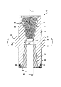
Socket 10, shown mounted at the end of a mooring cable 22, comprises
mainly a hollow socket body 12, preferably of metal, for example of forged,
cast
or machined steel. This body 12, of axial symmetry, has a shape elongated
along its longitudinal axis 16. In this embodiment, it has an internal cavity
14,
open at its ends, of general "hourglass" shape comprising three successive
parts aligned on longitudinal axis 16 and which are, in the following order:
- a guide chamber 34 for cable 22, in which chamber a retaining sleeve
36 is inserted,
- an intermediate section 18 and
- a fastening receptacle 20 receiving the end of cable 22.
In this case fastening receptacle 20 has frustoconical shape, constructed
such that it flares with distance from narrow intermediate section 18 along
axis
16.
In this case narrow intermediate section 18 is a middle section in which
the center of gravity G of socket 10 is situated. It is therefore particularly
CA 02808960 2013-02-20
8
advantageous to provide that socket body 12 is equipped in this zone with
means for coupling socket 10, in this case journals 30 and 30', with the
element
to be anchored.
Guide chamber 34 prolongs fastening receptacle 20 upstream on the
other side of intermediate section 18. This guide chamber 34, equipped with
sleeve 36, closely conforms to the end of cable 22, which it receives in order
to
fulfill its function as cable stiffener.
Depending on diverse anchoring applications, especially in the marine
(or offshore) environment, mooring cable 22 may be traditionally formed of a
helically twisted assembly of strands constituted of individual wires, or of
cores
26 enveloped in a watertight sheath 24. These individual wires or these cores
are themselves formed from wires of steel or of synthetic or mixed material
(steel and synthetic materials).
It will be noted that intermediate section 18, the diameter of which is
smaller than internal cavity 14, has a diameter compatible with the outside
diameter of cable 22 coated with its protective sheath 24.
The fixation of socket 10 to the end of cable 22 is achieved in the
following manner: socket 10 is set in place on the sheaf created by spreading
the end of strands 26 of cable 22, after this has been stripped at its end. A
molten metal or a synthetic material 28 is then poured from the top of cavity
14
in chamber 20, forming the fastening receptacle, with the result that, after
it
solidifies and/or hardens, the cable and the socket are made irreversibly
integral, by the fact that a wedging cone is obtained by undercut effect.
To permit its fixation to an element to be anchored, in general a floating
mobile element such as an offshore oil and gas platform or a loading buoy, but
which may also be, at the other end of the cable, an anchor on the sea floor,
etc., socket 10 comprises coupling means capable of cooperating with
corresponding coupling means provided on the element to be anchored_
CA 02808960 2013-02-20
9
These coupling means are generally intended to assure a pivoting
connection, preferably without play or with optimized play, which will permit
continuous self-alignment of the socket with the cable on which it is fastened
according to the different forces to which the anchoring system is subjected.
In the=alternative embodiment described here, these coupling means are
constituted by two journals 30 and 30' disposed oppositely such that their
common axis of rotation 32 is orthogonal to longitudinal axis 16 of socket 10
and defines the pivoting axis thereof. The mobile element to be anchored will
then be provided with coupling means of female type, such as bayonet clamps,
in which the journals will then engage.
Preferably coupling means 30, 30' of socket 10 are disposed on socket
body 12 such that their axis of rotation 32 passes close to the base of
fastening
receptacle 20, at the level of intermediate section 18.
In practice, and with reference to the present variant, it will be noted that
a substantial effect of positioning of coupling means 30, 30' is obtained when
pivoting axis 32 passes through the intermediate section of the socket
indicated
by R in the figure, in other words a zone extending between the base of
fastening receptacle 20 and the start of guide chamber 34.
Preferably socket 10 will be designed in order that its center of gravity G
is located In this region R, and therefore in immediate proximity to pivoting
axis
32, in order to achieve equilibrium that is no different or almost no
different from
that during its rotation around pivot 32.
The advantageous character of a flared shape for guide chamber 34,
situated in the extension of intermediate section 18, on the side opposite
fastening receptacle 20, is emphasized once again. Intermediate section
therefore opens onto this chamber 34 of flared shape, in this case
frustoconical,
although it may nevertheless have other shapes, permitting guided retention
and protection of the cable over a certain distance after intermediate one 18,
CA 02808960 2013-02-20
advantageously by virtue of the presence of a sleeve 36 of added plastic
material.
Sleeve 36 is inserted into flared chamber 34, and its shape is
complementary thereto. After socket 10 has been fastened on its cable 22, this
sleeve 36 of plastic, preferably rigid material, becomes a retaining sleeve
disposed around the cable. It then makes it possible to absorb the deviations
thereof that could still occur at the outlet of the socket, and prevents or
very
greatly limits its kinking directly at the level of intermediate zone 18.
Appropriate
materials for sleeve 36 may be polyurethanes of diverse grades, among others.
Sleeve 36 is retained in guide chamber 34 by means In this case of a
retaining ring 38 fixed to body 12 by a circle of screws 39.
It will be possible to provide an 0-ring seal, although not illustrated,
around cable 22 at the level of Intermediate section 18.
In addition, sheath 24 of cable 22 may be blocked In place in socket 10
by means, for example, or circlips or retaining rings engaging in an annular
groove made in sheath 24 of the cable.
It is self-evident that the Invention could not be limited to the exemplary
embodiment considered, but that it extends to multiple variants and
equivalents
provided the main technical characteristics thereof are respected.
Its scope of application extends to any mooring line, in the case in which
it is desired to directly assure natural self-alignment of the cable with its
end
socket or sockets so as to minimize the parasitic bending stresses to which
the
cable is subjected at the outlet thereof and which are very often responsible
for
its being prematurely scrapped.