Note: Descriptions are shown in the official language in which they were submitted.
WO 2012/030366 CA 02809044 2013-02-21PCT/US2010/060629
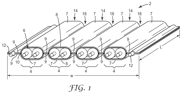
SHIELDED ELECTRICAL CABLE
TECHNICAL FIELD
[0001] The present disclosure relates generally to shielded electrical
cables
for the transmission of electrical signals, in particular, to shielded
electrical cables that can
be mass-terminated and provide high speed electrical properties.
BACKGROUND
[0002] Due to increasing data transmission speeds used in modern
electronic devices, there is a demand for electrical cables that can
effectively transmit high
speed electromagnetic signals (e.g., greater than 1 Gb/s). One type of cable
used for these
purposes are coaxial cables. Coaxial cables generally include an electrically
conductive
wire surrounded by an insulator. The wire and insulator are surrounded by a
shield, and
the wire, insulator, and shield are surrounded by a jacket. Another type of
electrical cable
is a shielded electrical cable having one or more insulated signal conductors
surrounded by
a shielding layer formed, for example, by a metal foil.
[0003] Both these types of electrical cable may require the use of
specifically designed connectors for termination and are often not suitable
for the use of
mass-termination techniques, e.g., the simultaneous connection of a plurality
of
conductors to individual contact elements. Although electrical cables have
been developed
to facilitate these mass-termination techniques, these cables often have
limitations in the
ability to mass-produce them, in the ability to prepare their termination
ends, in their
flexibility, and in their electrical performance.
SUMMARY
[0004] The present disclosure is to directed to high speed electrical data
cables. In one embodiment, a shielded electrical cable, comprises a plurality
of conductor
sets extending along a length of the cable and being spaced apart from each
other along a
1
WO 2012/030366 CA 02809044 2013-02-21PCT/US2010/060629
width of the cable. Each conductor set includes one or more insulated
conductors. The
cable also comprises first and second shielding films disposed on opposite
sides of the
cable. The first and second films include cover portions and pinched portions
arranged
such that, in transverse cross section, the cover portions of the first and
second films in
combination substantially surround each conductor set. The pinched portions of
the first
and second films in combination form pinched portions of the cable on each
side of each
conductor set. The cable further comprises a first adhesive layer bonding the
first
shielding film to the second shielding film in the pinched portions of the
cable. The
plurality of conductor sets comprises a first conductor set that comprises
neighboring first
and second insulated conductors and has corresponding first cover portions of
the first and
second shielding films and corresponding first pinched portions of the first
and second
shielding films forming a first pinched cable portion on one side of the first
conductor set.
A selected one of the insulated conductors has a wire diameter no greater than
24
American wire gauge (AWG), and a transverse bending of the cable at a cable
location of
no more than 180 degrees over an inner radius of at most 2 mm causes a cable
impedance
of the selected insulated conductor proximate the cable location to vary by no
more than 2
percent from an initial cable impedance measured at the cable location in an
unbent
configuration.
[0005] In one configuration, the wire diameter of the selected insulated
conductor may be no greater than 26 AWG, and wherein a transverse bending of a
cable
location of no more than 180 degrees over an inner radius of at most 1 mm
causes the
cable impedance of the selected insulated conductor proximate the cable
location to vary
by no more than 1 percent from the initial cable impedance. In another
configuration, the
selected insulated conductor may be part of a selected one of the conductor
sets that
includes at least two insulated conductors each having a wire diameter no
greater than 24
AWG and a nominal differential impedance of 100 ohms. In such a case, the
transverse
bending of the cable causes a differential cable impedance of the selected
conductor set
proximate the cable location to vary by no more than 2 ohms from an initial
differential
cable impedance measured at the cable location in the unbent configuration.
Also in such
a case, the wire diameter of the at least two insulated conductors may be no
greater than
26 AWG, and therefore the transverse bending of a cable location of no more
than 180
2
WO 2012/030366 CA 02809044 2013-02-21PCT/US2010/060629
degrees over a second inner radius of at most 1 mm causes the differential
cable
impedance of the selected conductor set proximate the cable location to vary
by no more
than 1 ohm from the initial differential impedance.
[0006] In any of the embodiments above, the selected insulated conductor
may have a nominal cable impedance of 50 ohms, and in such a case the cable
impedance
of the selected insulated conductor proximate the cable location varies by no
more than 1
ohm from the initial cable impedance. In any of these embodiments, the cable
may further
comprise a bend of at least 45 degrees around a fold line that extends across
a width of the
cable, wherein the bend has an inner radius of at most 5 mm. In such a case,
the bend may
be at least 90 degrees and conforms to geometry of a structure that encloses
the cable,
and/or the bend may be at least 180 degrees and the fold line is at a fold
angle relative to a
longitudinal edge of the cable such that the cable turns at a turn angle in
response to
flattening of proximate regions before and after the bend to a plane. In the
latter case, the
fold angle may be 45 degrees, and the turn angle 90 degrees.
[0007] In another embodiment, a shielded electrical cable comprises a
plurality of conductor sets extending along a length of the cable and being
spaced apart
from each other along a width of the cable. Each conductor set includes one or
more
insulated conductors. The cable also comprises first and second shielding
films disposed
on opposite sides of the cable. The first and second films including cover
portions and
pinched portions arranged such that, in transverse cross section, the cover
portions of the
first and second films in combination substantially surround each conductor
set. The
pinched portions of the first and second films in combination form pinched
portions of the
cable on each side of each conductor set. The cable further comprises first
adhesive layer
bonding the first shielding film to the second shielding film in the pinched
portions of the
cable. The plurality of conductor sets comprises a first conductor set that
comprises
neighboring first and second insulated conductors and has corresponding first
cover
portions of the first and second shielding films and corresponding first
pinched portions of
the first and second shielding films forming a first pinched cable portion on
one side of the
first conductor set. A selected one of the insulated conductors has a wire
diameter no
greater than 24 American wire gauge (AWG), and a transverse bending of the
cable at a
cable location of no more than 180 degrees over an inner radius of at most 5
mm causes an
3
WO 2012/030366 CA 02809044 2013-02-21 PCT/US2010/060629
insertion loss of the selected insulated conductor proximate the cable
location to vary by
no more than 0.5 dB from an initial insertion loss measured at the cable
location in an
unbent configuration.
[0008] In this embodiment, the cable may further comprise a bend of at
least 45 degrees around a fold line that extends across a width of the cable,
wherein the
bend has an inner radius of at most 5 mm. In such a case, the bend may be at
least 90
degrees and conforms to geometry of a structure that encloses the cable,
and/or the bend
may be at least 180 degrees and the fold line is at a fold angle relative to a
longitudinal
edge of the cable such that the cable turns at a turn angle in response to
flattening of
proximate regions before and after the bend to a plane. In the latter case,
the fold angle
may be 45 degrees, and the turn angle 90 degrees.
[0009] In another embodiment of the invention, a shielded electrical cable
comprises a plurality of conductor sets extending along a length of the cable
and being
spaced apart from each other along a width of the cable. Each conductor set
includes one
or more insulated conductors. The cable also comprises first and second
shielding films
disposed on opposite sides of the cable. The first and second films include
cover portions
and pinched portions arranged such that, in transverse cross section, the
cover portions of
the first and second films in combination substantially surround each
conductor set. The
pinched portions of the first and second films in combination form pinched
portions of the
cable on each side of each conductor set. The cable further includes a first
adhesive layer
bonding the first shielding film to the second shielding film in the pinched
portions of the
cable. The plurality of conductor sets comprises a first conductor set that
comprises
neighboring first and second insulated conductors and has corresponding first
cover
portions of the first and second shielding films and corresponding first
pinched portions of
the first and second shielding films forming a first pinched cable portion on
one side of the
first conductor set. An application of a force on the cable, the cable being
simply
supported between two supporting points that are 3.0 inches apart and the
force being
applied midpoint between the supporting points, results in a deflection in the
direction of
the force of at least one inch. The force, measured in pounds-force, does not
exceed the
sum of individual forces for each of the insulated conductors, the individual
forces being
4
WO 2012/030366 CA 02809044 2013-02-21PCT/US2010/060629
equal to 11000 times a wire diameter cubed of the respective insulated
conductor, the wire
diameter being expressed in inches.
[0010] In one arrangement, the wire diameter may be no greater than 24
American wire gauge (AWG). In any of these arrangements, the maximum force may
occur when the deflection is between 1 inch and 1.5 inches. Similarly, the
cable in any of
these arrangement may further comprise a bend of at least 45 degrees around a
fold line
that extends across a width of the cable, wherein the bend has an inner radius
of at most 5
mm. In such a case, the bend may be at least 90 degrees and conform to
geometry of a
structure that encloses the cable. Or, in such a case, the bend may be at
least 180 degrees
and the fold line is at a fold angle relative to a longitudinal edge of the
cable such that the
cable turns at a turn angle in response to flattening of proximate regions
before and after
the bend to a plane. For example, the fold angle may 45 degrees, and the turn
angle 90
degrees.
[0011] In another embodiment of the invention, a cable assembly
comprises a shielded electrical cable. The cable comprises a plurality of
conductor sets
extending along a length of the cable and being spaced apart from each other
along a
width of the cable. Each conductor set includes one or more insulated
conductors. The
cable also comprises first and second shielding films disposed on opposite
sides of the
cable. The first and second films include cover portions and pinched portions
arranged
such that, in transverse cross section, the cover portions of the first and
second films in
combination substantially surround each conductor set. The pinched portions of
the first
and second films in combination form pinched portions of the cable on each
side of each
conductor set. The cable further includes a first adhesive layer bonding the
first shielding
film to the second shielding film in the pinched portions of the cable. The
plurality of
conductor sets comprises a first conductor set that comprises neighboring
first and second
insulated conductors and has corresponding first cover portions of the first
and second
shielding films and corresponding first pinched portions of the first and
second shielding
films forming a first pinched cable portion on one side of the first conductor
set. The
cable assembly further comprises an electrical connector encompassing at least
the bend in
the cable, wherein at least one of the insulated conductors is electrically
coupled to at least
one contact of the electrical connector.
5
WO 2012/030366 CA 02809044 2013-02-21PCT/US2010/060629
[0012] In one arrangement, the electrical connector may comprise an
overmold formed onto the cable and/or a multi-piece housing. In any of these
arrangements, the connector may comprise a paddle card connector. Similarly,
the bend
may be at least 90 degrees around the fold line in these arrangements, and the
inner radius
of the bend may be at most 1 mm. In any of these arrangements, the connector
may
disposed on an end of the cable and/or a middle portion of the cable. The
insulated
conductors may have a wire diameter of no more than 24 American wire gauge
(AWG).
[0013] In any of these variations, the cable may further include a second
bend not encompassed by the electrical connector, the second bend being of at
least 45
degrees around a second fold line that extends across a width of the cable,
wherein the
second bend has an inner radius of at most 5 mm. The second bend may be at
least 90
degrees and conforms to geometry of a structure that encloses the cable
assembly, and/or
the second bend may be at least 180 degrees and the second fold line is at a
fold angle
relative to a longitudinal edge of the cable such that the cable turns at a
turn angle in
response to flattening of proximate regions before and after the second bend
to a plane. In
such a case, the second fold angle may be 45 degrees, and the turn angle is 90
degrees. In
any of these embodiments, the at least one conductor set of the respective
cables may be
adapted for maximum data transmission rates of at least 1 Gb/s.
[0014] These and various other characteristics are pointed out with
particularity in the claims annexed hereto and form a part hereof. Reference
should also be
made to the drawings which form a further part hereof, and to accompanying
descriptive
matter, in which there are illustrated and described representative examples
of systems,
apparatuses, and methods.
BRIEF DESCRIPTION OF THE DRAWINGS
[0015] FIG. 1 is a perspective view of an example shielded electrical cable;
[0016] FIGS. 2a-2g are front cross-sectional views of further example
shielded electrical cables;
[0017] FIGS. 3a-3d are top views that illustrate different procedures of an
example termination process of a shielded electrical cable to a termination
component;
6
WO 2012/030366 CA 02809044 2013-02-21PCT/US2010/060629
[0018] FIGS. 4a-4c are front cross-sectional views of still further example
shielded electrical cables;
[0019] FIGS. 5a-5e are perspective views illustrating an example method
of making a shielded electrical cable;
[0020] FIGS. 6a-6c are front cross-sectional views illustrating a detail of
an
example method of making a shielded electrical cable;
[0021] FIGS. 7a and 7b are front cross-sectional detail views illustrating
another aspect of making an example shielded electrical cable;
[0022] FIG. 8a is a front cross-sectional view of another example
embodiment of a shielded electrical cable, and FIG. 8b is a corresponding
detail view
thereof;
[0023] FIG. 9 is a front cross-sectional view of a portion of another
example shielded electrical cable;
[0024] FIG. 10 is a front cross-sectional view of a portion of another
example shielded electrical cable;
[0025] FIGS. ha and lib are front cross-sectional views of two other
portions of example shielded electrical cables;
[0026] FIG. 12 is a graph comparing the electrical isolation performance of
an example shielded electrical cable to that of a conventional electrical
cable;
[0027] FIG. 13 is a front cross-sectional view of another example shielded
electrical cable;
[0028] FIG. 14 is a perspective view of an example shielded electrical
ribbon cable application;
[0029] FIGS. 15 and 16 are side views of bending/folding of an example
cable;
[0030] FIG. 17 is a block diagram illustrating an example test setup for
measuring force versus deflection of a cable;
[0031] FIGS. 18 and 19 are graphs showing results of example force-
deflection tests for cables;
[0032] FIG. 20 is a logarithmic graph summarizing average values of
force-deflection tests for example cables;
7
WO 2012/030366 CA 02809044 2013-02-21 PCT/US2010/060629
[0033] FIG. 21 is a graph showing time domain reflectometer
measurements of differential impedance at a bend regions for a cable according
to an
example embodiment; and
[0034] FIGS. 22-27 are side cross-sectional views of connectors according
to example embodiments.
[0035] In the figures, like reference numerals designate like elements.
DETAILED DESCRIPTION
[0036] In the following description, reference is made to the accompanying
drawings that form a part hereof, and in which is shown by way of illustration
various
embodiments in which the invention may be practiced. It is to be understood
that other
embodiments may be utilized, as structural and operational changes may be made
without
departing from the scope of the present invention. The following detailed
description,
therefore, is not to be taken in a limiting sense, and the scope of the
invention is defined
by the appended claims.
[0037] A growing number of applications require high speed (e.g., > 1
Gb/s) high signal integrity connections. These applications may include
enterprise
computing, network communication, factory automation, medical, test and
instrumentation, etc. These applications may use twin axial ("twinax")
transmission lines
that include parallel pairs of differentially-driven conductors. Each pair of
conductors may
be dedicated to a data transmission channel. The construction of choice for
these purposes
is often a jacketed loose bundle of shielded paired conductors. The jacket is
often formed
from shielding and/or insulating wrapped in a helical pattern around the
conductor bundle.
[0038] Applications are demanding more speed from these channels and
more channels per assembly. As a result, there will be a need for cables with
improved
termination signal integrity, termination cost, impedance/skew control, and
cable cost over
current twinax transmission lines. The present disclosure is generally
directed to a
shielded electrical ribbon cable that is suitable for, among other things,
differentially
driven conductor sets. Due to the ribbon construction, the cable can readily
be terminated
8
WO 2012/030366 CA 02809044 2013-02-21PCT/US2010/060629
to a printed circuit board connector of similar pitch. Such a termination can
provide very
high termination signal integrity. The construction of this type of cable may
generally
include parallel insulated wires that are bonded to a substrate on one or both
sides with
specific placement of gaps between conductors. The substrates may or may not
contain a
ground plane. Such a cable may be used as an alternative to conventional
bundled, e.g.,
differential pair, twin-axial (twinax) constructions and is expected to have
lower cable
cost, termination cost, skew, and termination parasitics.
[0039] Shielded cables currently used in high performance and high speed
applications are generally not sharply bent because this may cause impedance
discontinuities at the bend location. Such discontinuities can produce
unwanted
reflections and poor overall electrical performance. For example, a
conventional parallel
pair twinax cable for gigabit data applications may be constructed with an
overlapped
shield (helical wrap) and an outer layer of polymer film to maintain the
wrapped shield in
place while bending. The wrapped layers add significant stiffness to the cable
for bending,
and also can cause pinching and local geometry changes within the cable at the
bend
locations. This results in significant changes in cable characteristics (e.g.,
impedance) at
and proximate to the bend.
[0040] Compared to conventional, wrapped, parallel-pair, twinax cables,
the ribbon cable structures described in the present disclosure may exhibit
improved
performance in applications that require sharp bending of the cable. These
shield
structures and cable constructions can maintain high cable electrical
performance even
after sharp bending. For example, such ribbon cables may be used with
connectors that
require the cable be sharply bent within the connector. The constructions can
also provide
much lower stiffness (e.g., up to one half) on bending than conventional
wrapped
constructions with similar materials. The lower stiffness and minimal impact
on electrical
performance under bending allows such cables to be bent more sharply than
conventional
cables, thereby saving space and providing enhanced routability in a given
application.
[0041] It is noted that the various sections and section headings are
provided for improved organization and convenience, and are not to be
construed in a
limiting way. For example, the sections and section headings are not to be
construed to
mean that techniques, methods, features, or components of one section cannot
be used
9
CA 02809044 2013-02-21
WO 2012/030366 PCT/US2010/060629
with techniques, methods, features, or components of a different section. On
the contrary,
we intend for any information from any given section or sections to also be
applicable to
information in any other section or sections, unless otherwise clearly
indicated to the
contrary.
SECTION 1: SHIELDED ELECTRICAL CABLE
CONSTRUCTIONS AND FEATURES
[0042] As the number and speed of interconnected devices increases,
electrical cables that carry signals between such devices need to be smaller
and capable of
carrying higher speed signals without unacceptable interference or crosstalk.
Shielding is
used in some electrical cables to reduce interactions between signals carried
by
neighboring conductors. Many of the cables described herein have a generally
flat
configuration, and include conductor sets that extend along a length of the
cable, as well as
electrical shielding films disposed on opposite sides of the cable. Pinched
portions of the
shielding films between adjacent conductor sets help to electrically isolate
the conductor
sets from each other. Many of the cables also include drain wires that
electrically connect
to the shields, and extend along the length of the cable. The cable
configurations
described herein can help to simplify connections to the conductor sets and
drain wires,
reduce the size of the cable connection sites, and/or provide opportunities
for mass
termination of the cable.
[0043] In FIG. 1 an exemplary shielded electrical cable 2 is shown that
includes a plurality of conductor sets 4 spaced apart from each other along
all or a portion
of a width, w, of the cable 2 and extend along a length, L, of the cable 2.
The cable 2 may
be arranged generally in a planar configuration as illustrated in Fig. 1 or
may be folded at
one or more places along its length into a folded configuration. In some
implementations,
some parts of cable 2 may be arranged in a planar configuration and other
parts of the
cable may be folded. In some configurations, at least one of the conductor
sets 4 of the
cable 2 includes two insulated conductors 6 extending along a length, L, of
cable 2. The
two insulated conductors 6 of the conductor sets 4 may be arranged
substantially parallel
along all or a portion of the length, L, of the cable 2. Insulated conductors
6 may include
10
WO 2012/030366 CA 02809044 2013-02-21PCT/US2010/060629
insulated signal wires, insulated power wires, or insulated ground wires. Two
shielding
films 8 are disposed on opposite sides of the cable 2.
[0044] The first and second shielding films 8 are arranged so that, in
transverse cross section, cable 2 includes cover regions 14 and pinched
regions 18. In the
cover regions 14 of the cable 2, cover portions 7 of the first and second
shielding films 8
in transverse cross section substantially surround each conductor set 4. For
example,
cover portions of the shielding films may collectively encompass at least 75%,
or at least
80, 85, or 90% of the perimeter of any given conductor set. Pinched portions 9
of the first
and second shielding films form the pinched regions 18 of cable 2 on each side
of each
conductor set 4. In the pinched regions 18 of the cable 2, one or both of the
shielding
films 8 are deflected, bringing the pinched portions 9 of the shielding films
8 into closer
proximity. In some configurations, as illustrated in Fig. 1, both of the
shielding films 8 are
deflected in the pinched regions 18 to bring the pinched portions 9 into
closer proximity.
In some configurations, one of the shielding films may remain relatively flat
in the
pinched regions 18 when the cable is in a planar or unfolded configuration,
and the other
shielding film on the opposite side of the cable may be deflected to bring the
pinched
portions of the shielding film into closer proximity.
[0045] The cable 2 may also include an adhesive layer 10 disposed
between shielding films 8 at least between the pinched portions 9. The
adhesive layer 10
bonds the pinched portions 9 of the shielding films 8 to each other in the
pinched regions
18 of the cable 2. The adhesive layer 10 may or may not be present in the
cover region 14
of the cable 2.
[0046] In some cases, conductor sets 4 have a substantially curvilinearly-
shaped envelope or perimeter in transverse cross-section, and shielding films
8 are
disposed around conductor sets 4 such as to substantially conform to and
maintain the
cross-sectional shape along at least part of, and preferably along
substantially all of, the
length L of the cable 6. Maintaining the cross-sectional shape maintains the
electrical
characteristics of conductor sets 4 as intended in the design of conductor
sets 4. This is an
advantage over some conventional shielded electrical cables where disposing a
conductive
shield around a conductor set changes the cross-sectional shape of the
conductor set.
11
WO 2012/030366 CA 02809044 2013-02-21PCT/US2010/060629
[0047] Although in the embodiment illustrated in FIG. 1, each conductor
set 4 has exactly two insulated conductors 6, in other embodiments, some or
all of the
conductor sets may include only one insulated conductor, or may include more
than two
insulated conductors 6. For example, an alternative shielded electrical cable
similar in
design to that of FIG. 1 may include one conductor set that has eight
insulated conductors
6, or eight conductor sets each having only one insulated conductor 6. This
flexibility in
arrangements of conductor sets and insulated conductors allows the disclosed
shielded
electrical cables to be configured in ways that are suitable for a wide
variety of intended
applications. For example, the conductor sets and insulated conductors may be
configured
to form: a multiple twinaxial cable, i.e., multiple conductor sets each having
two insulated
conductors; a multiple coaxial cable, i.e., multiple conductor sets each
having only one
insulated conductor; or combinations thereof In some embodiments, a conductor
set may
further include a conductive shield (not shown) disposed around the one or
more insulated
conductors, and an insulative jacket (not shown) disposed around the
conductive shield.
[0048] In the embodiment illustrated in FIG. 1, shielded electrical cable 2
further includes optional ground conductors 12. Ground conductors 12 may
include
ground wires or drain wires. Ground conductors 12 can be spaced apart from and
extend
in substantially the same direction as insulated conductors 6. Shielding films
8 can be
disposed around ground conductors 12. The adhesive layer 10 may bond shielding
films 8
to each other in the pinched portions 9 on both sides of ground conductors 12.
Ground
conductors 12 may electrically contact at least one of the shielding films 8.
[0049] The cross-sectional views of FIGS. 2a-2g may represent various
shielded electrical cables, or portions of cables. In FIG. 2a, shielded
electrical cable 102a
includes a single conductor set 104. Conductor set 104 extends along the
length of the
cable and has only a single insulated conductor 106. If desired, the cable
102a may be
made to include multiple conductor sets 104 spaced apart from each other
across a width
of the cable 102a and extending along a length of the cable. Two shielding
films 108 are
disposed on opposite sides of the cable. The cable 102a includes a cover
region 114 and
pinched regions 118. In the cover region 114 of the cable 102a, the shielding
films 108
include cover portions 107 that cover the conductor set 104. In transverse
cross section,
the cover portions 107, in combination, substantially surround the conductor
set 104. In
12
WO 2012/030366 CA 02809044 2013-02-21PCT/US2010/060629
the pinched regions 118 of the cable 102a, the shielding films 108 include
pinched
portions 109 on each side of the conductor set 104.
[0050] An optional adhesive layer 110 may be disposed between shielding
films 108. Shielded electrical cable 102a further includes optional ground
conductors 112.
Ground conductors 112 are spaced apart from and extend in substantially the
same
direction as insulated conductor 106. Conductor set 104 and ground conductors
112 can
be arranged so that they lie generally in a plane as illustrated in FIG. 2a.
[0051] Second cover portions 113 of shielding films 108 are disposed
around, and cover, the ground conductors 112. The adhesive layer 110 may bond
the
shielding films 108 to each other on both sides of ground conductors 112.
Ground
conductors 112 may electrically contact at least one of shielding films 108.
In FIG. 2a,
insulated conductor 106 and shielding films 108 are effectively arranged in a
coaxial cable
configuration. The coaxial cable configuration of FIG. 2a can be used in a
single ended
circuit arrangement.
[0052] As illustrated in the transverse cross sectional view of FIG. 2a,
there
is a maximum separation, D, between the cover portions 107 of the shielding
films 108,
and there is a minimum separation, dl, between the pinched portions 109 of the
shielding
films 108.
[0053] In FIG. 2a, adhesive layer 110 is shown disposed between the
pinched portions 109 of the shielding films 108 in the pinched regions 118 of
the cable
102 and disposed between the cover portions 107 of the shielding films 108 and
the
insulated conductor 106 in the cover region 114 of the cable 102a. In this
arrangement,
the adhesive layer 110 bonds the pinched portions 109 of the shielding films
108 together
in the pinched regions 118 of the cable, and bonds the cover portions 107 of
the shielding
films 108 to the insulated conductor 106 in the cover region 114 of the cable
102a.
[0054] Shielded cable 102b of FIG. 2b is similar to cable 102a of FIG. 2a,
with similar elements identified by similar reference numerals, except that in
FIG. 2b, the
optional adhesive layer 110b is not present between the cover portions 107 of
the shielding
films 108 and the insulated conductor 106 in the cover region 114 of the cable
102. In this
arrangement, the adhesive layer 110b bonds the pinched portions 109 of the
shielding
films 108 together in the pinched regions 118 of the cable, but the adhesive
layer 110 does
13
WO 2012/030366 CA 02809044 2013-02-21PCT/US2010/060629
not bond cover portions 107 of the shielding films 108 to the insulated
conductor 106 in
the cover regions 114 of the cable 102.
[0055] Referring to FIG. 2c, shielded electrical cable 102c is similar to
shielded electrical cable 102a of FIG. 2a, except that cable 102c has a single
conductor set
104c which has two insulated conductors 106c. If desired, the cable 102c may
be made to
include multiple conductor sets 104c spaced part across a width of the cable
102c and
extending along a length of the cable. Insulated conductors 106c are arranged
generally in
a single plane and effectively in a twinaxial configuration. The twin axial
cable
configuration of FIG. 2c can be used in a differential pair circuit
arrangement or in a single
ended circuit arrangement.
[0056] Two shielding films 108c are disposed on opposite sides of
conductor set 104c. The cable 102c includes a cover region 114c and pinched
regions
118c. In the cover region 114c of the cable 102c, the shielding films 108c
include cover
portions 107c that cover the conductor set 104c. In transverse cross section,
the cover
portions 107c, in combination, substantially surround the conductor set 104c.
In the
pinched regions 118c of the cable 102c, the shielding films 108c include
pinched portions
109c on each side of the conductor set 104c.
[0057] An optional adhesive layer 110c may be disposed between shielding
films 108c. Shielded electrical cable 102c further includes optional ground
conductors
112c similar to ground conductors 112 discussed previously. Ground conductors
112c are
spaced apart from, and extend in substantially the same direction as,
insulated conductors
106c. Conductor set 104c and ground conductors 112c can be arranged so that
they lie
generally in a plane as illustrated in FIG. 2c.
[0058] As illustrated in the cross section of FIG. 2c, there is a maximum
separation, D, between the cover portions 107c of the shielding films 108c;
there is a
minimum separation, dl, between the pinched portions 109c of the shielding
films 108c;
and there is a minimum separation, d2, between the shielding films 108c
between the
insulated conductors 106c.
[0059] FIG. 2c shows the adhesive layer 110c disposed between the
pinched portions 109c of the shielding films 108c in the pinched regions 118c
of the cable
102c and disposed between the cover portions 107c of the shielding films 108c
and the
14
WO 2012/030366 CA 02809044 2013-02-21PCT/US2010/060629
insulated conductors 106c in the cover region 114c of the cable 102c. In this
arrangement,
the adhesive layer 110c bonds the pinched portions 109c of the shielding films
108c
together in the pinched regions 118c of the cable 102c, and also bonds the
cover portions
107c of the shielding films 108c to the insulated conductors 106c in the cover
region 114c
of the cable 102c.
[0060] Shielded cable 102d of FIG. 2d is similar to cable 102c of FIG. 2c,
with similar elements identified by similar reference numerals, except that in
cable 102d
the optional adhesive layer 110d is not present between the cover portions
107c of the
shielding films 108c and the insulated conductors 106c in the cover region
114c of the
cable. In this arrangement, the adhesive layer 110d bonds the pinched portions
109c of the
shielding films 108c together in the pinched regions 118c of the cable, but
does not bond
the cover portions 107c of the shielding films 108c to the insulated
conductors 106c in the
cover region 114c of the cable 102d.
[0061] Referring now to FIG. 2e, we see there a transverse cross-sectional
view of a shielded electrical cable 102e similar in many respects to the
shielded electrical
cable 102a of FIG. 2a. However, where cable 102a includes a single conductor
set 104
having only a single insulated conductor 106, cable 102e includes a single
conductor set
104e that has two insulated conductors 106e extending along a length of the
cable 102e.
Cable 102e may be made to have multiple conductor sets 104e spaced apart from
each
other across a width of the cable 102e and extending along a length of the
cable 102e.
Insulated conductors 106e are arranged effectively in a twisted pair cable
arrangement,
whereby insulated conductors 106e twist around each other and extend along a
length of
the cable 102e.
[0062] In FIG. 2f another shielded electrical cable 102f is shown that is
also similar in many respects to the shielded electrical cable 102a of FIG.
2a. However,
where cable 102a includes a single conductor set 104 having only a single
insulated
conductor 106, cable 102f includes a single conductor set 104f that has four
insulated
conductors 106f extending along a length of the cable 102f. The cable 102f may
be made
to have multiple conductor sets 104f spaced apart from each other across a
width of the
cable 102f and extending along a length of the cable 102f.
15
WO 2012/030366 CA 02809044 2013-02-21PCT/US2010/060629
[0063] Insulated conductors 106f are arranged effectively in a quad cable
arrangement, whereby insulated conductors 106f may or may not twist around
each other
as insulated conductors 106f extend along a length of the cable 102f.
[0064] Referring back to FIGS. 2a-2f, further embodiments of shielded
electrical cables may include a plurality of spaced apart conductor sets 104,
104c, 104e, or
104f, or combinations thereof, arranged generally in a single plane.
Optionally, the
shielded electrical cables may include a plurality of ground conductors 112
spaced apart
from, and extending generally in the same direction as, the insulated
conductors of the
conductor sets. In some configurations, the conductor sets and ground
conductors can be
arranged generally in a single plane. FIG. 2g illustrates an exemplary
embodiment of such
a shielded electrical cable.
[0065] Referring to FIG. 2g, shielded electrical cable 102g includes a
plurality of spaced apart conductor sets 104, 104c arranged generally in
plane. Shielded
electrical cable 102g further includes optional ground conductors 112 disposed
between
conductor sets 104, 104c and at both sides or edges of shielded electrical
cable 102g.
[0066] First and second shielding films 208 are disposed on opposite sides
of the cable 102g and are arranged so that, in transverse cross section, the
cable 102g
includes cover regions 224 and pinched regions 228. In the cover regions 224
of the
cable, cover portions 217 of the first and second shielding films 208 in
transverse cross
section substantially surround each conductor set 104, 104c. Pinched portions
219 of the
first and second shielding films 208 form the pinched regions 218 on two sides
of each
conductor set 104, 104c.
[0067] The shielding films 208 are disposed around ground conductors
112. An optional adhesive layer 210 is disposed between shielding films 208
and bonds
the pinched portions 219 of the shielding films 208 to each other in the
pinched regions
228 on both sides of each conductor set 104, 104c. Shielded electrical cable
102g includes
a combination of coaxial cable arrangements (conductor sets 104) and a
twinaxial cable
arrangement (conductor set 104c) and may therefore be referred to as a hybrid
cable
arrangement.
[0068] One, two, or more of the shielded electrical cables may be
terminated to a termination component such as a printed circuit board, paddle
card, or the
16
WO 2012/030366 CA 02809044 2013-02-21PCT/US2010/060629
like. Because the insulated conductors and ground conductors can be arranged
generally
in a single plane, the disclosed shielded electrical cables are well suited
for mass-stripping,
i.e., the simultaneous stripping of the shielding films and insulation from
the insulated
conductors, and mass-termination, i.e., the simultaneous terminating of the
stripped ends
of the insulated conductors and ground conductors, which allows a more
automated cable
assembly process. This is an advantage of at least some of the disclosed
shielded
electrical cables. The stripped ends of insulated conductors and ground
conductors may,
for example, be terminated to contact conductive paths or other elements on a
printed
circuit board, for example. In other cases, the stripped ends of insulated
conductors and
ground conductors may be terminated to any suitable individual contact
elements of any
suitable termination device, such as, e.g., electrical contacts of an
electrical connector.
[0069] In FIGS. 3a-3d an exemplary termination process of shielded
electrical cable 302 to a printed circuit board or other termination component
314 is
illustrated. This termination process can be a mass-termination process and
includes the
steps of stripping (illustrated in FIGS. 3a-3b), aligning (illustrated in FIG.
3c), and
terminating (illustrated in FIG. 3d). When forming shielded electrical cable
302, which
may in general take the form of any of the cables shown and/or described
herein, the
arrangement of conductor sets 304, insulated conductors 306, and ground
conductors 312
of shielded electrical cable 302 may be matched to the arrangement of contact
elements
316 on printed circuit board 314, which would eliminate any significant
manipulation of
the end portions of shielded electrical cable 302 during alignment or
termination.
[0070] In the step illustrated in FIG. 3a, an end portion 308a of shielding
films 308 is removed. Any suitable method may be used, such as, e.g.,
mechanical
stripping or laser stripping. This step exposes an end portion of insulated
conductors 306
and ground conductors 312. In one aspect, mass-stripping of end portion 308a
of
shielding films 308 is possible because they form an integrally connected
layer that is
separate from the insulation of insulated conductors 306. Removing shielding
films 308
from insulated conductors 306 allows protection against electrical shorting at
these
locations and also provides independent movement of the exposed end portions
of
insulated conductors 306 and ground conductors 312. In the step illustrated in
FIG. 3b, an
end portion 306a of the insulation of insulated conductors 306 is removed. Any
suitable
17
WO 2012/030366 CA 02809044 2013-02-21PCT/US2010/060629
method may be used, such as, e.g., mechanical stripping or laser stripping.
This step
exposes an end portion of the conductor of insulated conductors 306. In the
step
illustrated in FIG. 3c, shielded electrical cable 302 is aligned with printed
circuit board
314 such that the end portions of the conductors of insulated conductors 306
and the end
portions of ground conductors 312 of shielded electrical cable 302 are aligned
with contact
elements 316 on printed circuit board 314. In the step illustrated in FIG. 3d,
the end
portions of the conductors of insulated conductors 306 and the end portions of
ground
conductors 312 of shielded electrical cable 302 are terminated to contact
elements 316 on
printed circuit board 314. Examples of suitable termination methods that may
be used
include soldering, welding, crimping, mechanical clamping, and adhesively
bonding, to
name a few.
[0071] In some cases, the disclosed shielded cables can be made to include
one or more longitudinal slits or other splits disposed between conductor
sets. The splits
may be used to separate individual conductor sets at least along a portion of
the length of
shielded cable, thereby increasing at least the lateral flexibility of the
cable. This may
allow, for example, the shielded cable to be placed more easily into a
curvilinear outer
jacket. In other embodiments, splits may be placed so as to separate
individual or multiple
conductor sets and ground conductors. To maintain the spacing of conductor
sets and
ground conductors, splits may be discontinuous along the length of shielded
electrical
cable. To maintain the spacing of conductor sets and ground conductors in at
least one
end portion of a shielded electrical cable so as to maintain mass-termination
capability, the
splits may not extend into one or both end portions of the cable. The splits
may be formed
in the shielded electrical cable using any suitable method, such as, e.g.,
laser cutting or
punching. Instead of or in combination with longitudinal splits, other
suitable shapes of
openings may be formed in the disclosed shielded electrical cables, such as,
e.g., holes,
e.g., to increase at least the lateral flexibility of the cable.
[0072] The shielding films used in the disclosed shielded cables can have a
variety of configurations and be made in a variety of ways. In some cases, one
or more
shielding films may include a conductive layer and a non-conductive polymeric
layer.
The conductive layer may include any suitable conductive material, including
but not
limited to copper, silver, aluminum, gold, and alloys thereof. The non-
conductive
18
WO 2012/030366 CA 02809044 2013-02-21PCT/US2010/060629
polymeric layer may include any suitable polymeric material, including but not
limited to
polyester, polyimide, polyamide-imide, polytetrafluoroethylene, polypropylene,
polyethylene, polyphenylene sulfide, polyethylene naphthalate, polycarbonate,
silicone
rubber, ethylene propylene diene rubber, polyurethane, acrylates, silicones,
natural rubber,
epoxies, and synthetic rubber adhesive. The non-conductive polymeric layer may
include
one or more additives and/or fillers to provide properties suitable for the
intended
application. In some cases, at least one of the shielding films may include a
laminating
adhesive layer disposed between the conductive layer and the non-conductive
polymeric
layer. For shielding films that have a conductive layer disposed on a non-
conductive
layer, or that otherwise have one major exterior surface that is electrically
conductive and
an opposite major exterior surface that is substantially non-conductive, the
shielding film
may be incorporated into the shielded cable in several different orientations
as desired. In
some cases, for example, the conductive surface may face the conductor sets of
insulated
wires and ground wires, and in some cases the non-conductive surface may face
those
components. In cases where two shielding films are used on opposite sides of
the cable,
the films may be oriented such that their conductive surfaces face each other
and each face
the conductor sets and ground wires, or they may be oriented such that their
non-
conductive surfaces face each other and each face the conductor sets and
ground wires, or
they may be oriented such that the conductive surface of one shielding film
faces the
conductor sets and ground wires, while the non-conductive surface of the other
shielding
film faces conductor sets and ground wires from the other side of the cable.
[0073] In some cases, at least one of the shielding films may be or include
a stand-alone conductive film, such as a compliant or flexible metal foil. The
construction
of the shielding films may be selected based on a number of design parameters
suitable for
the intended application, such as, e.g., flexibility, electrical performance,
and
configuration of the shielded electrical cable (such as, e.g., presence and
location of
ground conductors). In some cases, the shielding films may have an integrally
formed
construction. In some cases, the shielding films may have a thickness in the
range of 0.01
mm to 0.05 mm. The shielding films desirably provide isolation, shielding, and
precise
spacing between the conductor sets, and allow for a more automated and lower
cost cable
manufacturing process. In addition, the shielding films prevent a phenomenon
known as
19
WO 2012/030366 CA 02809044 2013-02-21PCT/US2010/060629
"signal suck-out" or resonance, whereby high signal attenuation occurs at a
particular
frequency range. This phenomenon typically occurs in conventional shielded
electrical
cables where a conductive shield is wrapped around a conductor set.
[0074] As discussed elsewhere herein, adhesive material may be used in
the cable construction to bond one or two shielding films to one, some, or all
of the
conductor sets at cover regions of the cable, and/or adhesive material may be
used to bond
two shielding films together at pinched regions of the cable. A layer of
adhesive material
may be disposed on at least one shielding film, and in cases where two
shielding films are
used on opposite sides of the cable, a layer of adhesive material may be
disposed on both
shielding films. In the latter cases, the adhesive used on one shielding film
is preferably
the same as, but may if desired be different from, the adhesive used on the
other shielding
film. A given adhesive layer may include an electrically insulative adhesive,
and may
provide an insulative bond between two shielding films. Furthermore, a given
adhesive
layer may provide an insulative bond between at least one of shielding films
and insulated
conductors of one, some, or all of the conductor sets, and between at least
one of shielding
films and one, some, or all of the ground conductors (if any). Alternatively,
a given
adhesive layer may include an electrically conductive adhesive, and may
provide a
conductive bond between two shielding films. Furthermore, a given adhesive
layer may
provide a conductive bond between at least one of shielding films and one,
some, or all of
the ground conductors (if any). Suitable conductive adhesives include
conductive
particles to provide the flow of electrical current. The conductive particles
can be any of
the types of particles currently used, such as spheres, flakes, rods, cubes,
amorphous, or
other particle shapes. They may be solid or substantially solid particles such
as carbon
black, carbon fibers, nickel spheres, nickel coated copper spheres, metal-
coated oxides,
metal-coated polymer fibers, or other similar conductive particles. These
conductive
particles can be made from electrically insulating materials that are plated
or coated with a
conductive material such as silver, aluminum, nickel, or indium tin-oxide. The
metal-
coated insulating material can be substantially hollow particles such as
hollow glass
spheres, or may comprise solid materials such as glass beads or metal oxides.
The
conductive particles may be on the order of several tens of microns to
nanometer sized
20
WO 2012/030366 CA 02809044 2013-02-21PCT/US2010/060629
materials such as carbon nanotubes. Suitable conductive adhesives may also
include a
conductive polymeric matrix.
[0075] When used in a given cable construction, an adhesive layer is
preferably substantially conformable in shape relative to other elements of
the cable, and
conformable with regard to bending motions of the cable. In some cases, a
given adhesive
layer may be substantially continuous, e.g., extending along substantially the
entire length
and width of a given major surface of a given shielding film. In some cases,
the adhesive
layer may include be substantially discontinuous. For example, the adhesive
layer may be
present only in some portions along the length or width of a given shielding
film. A
discontinuous adhesive layer may for example include a plurality of
longitudinal adhesive
stripes that are disposed, e.g., between the pinched portions of the shielding
films on both
sides of each conductor set and between the shielding films beside the ground
conductors
(if any). A given adhesive material may be or include at least one of a
pressure sensitive
adhesive, a hot melt adhesive, a thermoset adhesive, and a curable adhesive.
An adhesive
layer may be configured to provide a bond between shielding films that is
substantially
stronger than a bond between one or more insulated conductor and the shielding
films.
This may be achieved, e.g., by appropriate selection of the adhesive
formulation. An
advantage of this adhesive configuration is to allow the shielding films to be
readily
strippable from the insulation of insulated conductors. In other cases, an
adhesive layer
may be configured to provide a bond between shielding films and a bond between
one or
more insulated conductor and the shielding films that are substantially
equally strong. An
advantage of this adhesive configuration is that the insulated conductors are
anchored
between the shielding films. When a shielded electrical cable having this
construction is
bent, this allows for little relative movement and therefore reduces the
likelihood of
buckling of the shielding films. Suitable bond strengths may be chosen based
on the
intended application. In some cases, a conformable adhesive layer may be used
that has a
thickness of less than about 0.13 mm. In exemplary embodiments, the adhesive
layer has
a thickness of less than about 0.05 mm.
[0076] A given adhesive layer may conform to achieve desired mechanical
and electrical performance characteristics of the shielded electrical cable.
For example,
the adhesive layer may conform to be thinner between the shielding films in
areas between
21
WO 2012/030366 CA 02809044 2013-02-21PCT/US2010/060629
conductor sets, which increases at least the lateral flexibility of the
shielded cable. This
may allow the shielded cable to be placed more easily into a curvilinear outer
jacket. In
some cases, an adhesive layer may conform to be thicker in areas immediately
adjacent the
conductor sets and substantially conform to the conductor sets. This may
increase the
mechanical strength and enable forming a curvilinear shape of shielding films
in these
areas, which may increase the durability of the shielded cable, for example,
during flexing
of the cable. In addition, this may help to maintain the position and spacing
of the
insulated conductors relative to the shielding films along the length of the
shielded cable,
which may result in more uniform impedance and superior signal integrity of
the shielded
cable.
[0077] A given adhesive layer may conform to effectively be partially or
completely removed between the shielding films in areas between conductor
sets, e.g., in
pinched regions of the cable. As a result, the shielding films may
electrically contact each
other in these areas, which may increase the electrical performance of the
cable. In some
cases, an adhesive layer may conform to effectively be partially or completely
removed
between at least one of the shielding films and the ground conductors. As a
result, the
ground conductors may electrically contact at least one of shielding films in
these areas,
which may increase the electrical performance of the cable. Even in cases
where a thin
layer of adhesive remains between at least one of shielding films and a given
ground
conductor, asperities on the ground conductor may break through the thin
adhesive layer
to establish electrical contact as intended.
[0078] In FIGS. 4a-4c, cross sectional views are shown of three exemplary
shielded electrical cables, which illustrate examples of the placement of
ground
conductors in the shielded electrical cables. An aspect of a shielded
electrical cable is
proper grounding of the shield, and such grounding can be accomplished in a
number of
ways. In some cases, a given ground conductor can electrically contact at
least one of the
shielding films such that grounding the given ground conductor also grounds
the shielding
film or films. Such a ground conductor may also be referred to as a "drain
wire".
Electrical contact between the shielding film and the ground conductor may be
characterized by a relatively low DC resistance, e.g., a DC resistance of less
than 10 ohms,
or less than 2 ohms, or of substantially 0 ohms. In some cases, a given ground
conductor
22
WO 2012/030366 CA 02809044 2013-02-21PCT/US2010/060629
may not electrically contact the shielding films, but may be an individual
element in the
cable construction that is independently terminated to any suitable individual
contact
element of any suitable termination component, such as, e.g., a conductive
path or other
contact element on a printed circuit board, paddle board, or other device.
Such a ground
conductor may also be referred to as a "ground wire". FIG. 4a illustrates an
exemplary
shielded electrical cable in which ground conductors are positioned external
to the
shielding films. FIGS. 4b and 4c illustrate embodiments in which the ground
conductors
are positioned between the shielding films, and may be included in the
conductor set. One
or more ground conductors may be placed in any suitable position external to
the shielding
films, between the shielding films, or a combination of both.
[0079] Referring to FIG. 4a, a shielded electrical cable 402a includes a
single conductor set 404a that extends along a length of the cable 402a.
Conductor set
404a has two insulated conductors 406, i.e., one pair of insulated conductors.
Cable 402a
may be made to have multiple conductor sets 404a spaced apart from each other
across a
width of the cable and extending along a length of the cable. Two shielding
films 408a
disposed on opposite sides of the cable include cover portions 407a. In
transverse cross
section, the cover portions 407a, in combination, substantially surround
conductor set
404a. An optional adhesive layer 410a is disposed between pinched portions
409a of the
shielding films 408a, and bonds shielding films 408a to each other on both
sides of
conductor set 404a. Insulated conductors 406 are arranged generally in a
single plane and
effectively in a twinaxial cable configuration that can be used in a single
ended circuit
arrangement or a differential pair circuit arrangement. The shielded
electrical cable 402a
further includes a plurality of ground conductors 412 positioned external to
shielding films
408a. Ground conductors 412 are placed over, under, and on both sides of
conductor set
404a. Optionally, the cable 402a includes protective films 420 surrounding the
shielding
films 408a and ground conductors 412. Protective films 420 include a
protective layer 421
and an adhesive layer 422 bonding protective layer 421 to shielding films 408a
and ground
conductors 412. Alternatively, shielding films 408a and ground conductors 412
may be
surrounded by an outer conductive shield, such as, e.g., a conductive braid,
and an outer
insulative jacket (not shown).
23
WO 2012/030366 CA 02809044 2013-02-21PCT/US2010/060629
[0080] Referring to FIG. 4b, a shielded electrical cable 402b includes a
single conductor set 404b that extends along a length of cable 402b. Conductor
set 404b
has two insulated conductors 406, i.e., one pair of insulated conductors.
Cable 402b may
be made to have multiple conductor sets 404b spaced apart from each other
across a width
of the cable and extending along the length of the cable. Two shielding films
408b are
disposed on opposite sides of the cable 402b and include cover portions 407b.
In
transverse cross section, the cover portions 407b, in combination,
substantially surround
conductor set 404b. An optional adhesive layer 410b is disposed between
pinched
portions 409b of the shielding films 408b and bonds the shielding films to
each other on
both sides of the conductor set. Insulated conductors 406 are arranged
generally in a
single plane and effectively in a twinaxial or differential pair cable
arrangement. Shielded
electrical cable 402b further includes a plurality of ground conductors 412
positioned
between shielding films 408b. Two of the ground conductors 412 are included in
conductor set 404b, and two of the ground conductors 412 are spaced apart from
conductor set 404b.
[0081] Referring to FIG. 4c, a shielded electrical cable 402c includes a
single conductor set 404c that extends along a length of cable 402c. Conductor
set 404c
has two insulated conductors 406, i.e., one pair of insulated conductors.
Cable 402c may
be made to have multiple conductor sets 404c spaced apart from each other
across a width
of the cable and extending along the length of the cable. Two shielding films
408c are
disposed on opposite sides of the cable 402c and include cover portions 407c.
In
transverse cross section, the cover portions 407c, in combination,
substantially surround
the conductor set 404c. An optional adhesive layer 410c is disposed between
pinched
portions 409c of the shielding films 408c and bonds shielding films 408c to
each other on
both sides of conductor set 404c. Insulated conductors 406 are arranged
generally in a
single plane and effectively in a twinaxial or differential pair cable
arrangement. Shielded
electrical cable 402c further includes a plurality of ground conductors 412
positioned
between shielding films 408c. All of the ground conductors 412 are included in
the
conductor set 404c. Two of the ground conductors 412 and insulated conductors
406 are
arranged generally in a single plane.
24
WO 2012/030366 CA 02809044 2013-02-21PCT/US2010/060629
[0082] The disclosed shielded cables can, if desired, be connected to a
circuit board or other termination component using one or more electrically
conductive
cable clips. For example, a shielded electrical cable may include a plurality
of spaced
apart conductor sets arranged generally in a single plane, and each conductor
set may
include two insulated conductors that extend along a length of the cable. Two
shielding
films may be disposed on opposite sides of the cable and, in transverse cross
section,
substantially surround each of the conductor sets. A cable clip may be clamped
or
otherwise attached to an end portion of the shielded electrical cable such
that at least one
of shielding films electrically contacts the cable clip. The cable clip may be
configured
for termination to a ground reference, such as, e.g., a conductive trace or
other contact
element on a printed circuit board, to establish a ground connection between
shielded
electrical cable and the ground reference. The cable clip may be terminated to
the ground
reference using any suitable method, including soldering, welding, crimping,
mechanical
clamping, and adhesively bonding, to name a few. When terminated, the cable
clip may
facilitate termination of end portions of the conductors of the insulated
conductors of the
shielded electrical cable to contact elements of a termination point, such as,
e.g., contact
elements on printed circuit board. The shielded electrical cable may include
one or more
ground conductors as described herein that may electrically contact the cable
clip in
addition to or instead of at least one of the shielding films.
[0083] In FIGS. 5a-5c an exemplary method of making a shielded electrical
cable is illustrated. Specifically, these figures illustrate an exemplary
method of making a
shielded electrical cable that may be substantially the same as that shown in
FIG. 1. In the
step illustrated in FIG. 5a, insulated conductors 506 are formed using any
suitable method,
such as, e.g., extrusion, or are otherwise provided. Insulated conductors 506
may be
formed of any suitable length. Insulated conductors 506 may then be provided
as such or
cut to a desired length. Ground conductors 512 (see FIG. Sc) may be formed and
provided
in a similar fashion.
[0084] In the step illustrated in FIG. 5b, shielding films 508 are formed. A
single layer or multilayer web may be formed using any suitable method, such
as, e.g.,
continuous wide web processing. Shielding films 508 may be formed of any
suitable
length. Shielding films 508 may then be provided as such or cut to a desired
length and/or
25
WO 2012/030366 CA 02809044 2013-02-21PCT/US2010/060629
width. Shielding films 508 may be pre-formed to have transverse partial folds
to increase
flexibility in the longitudinal direction. One or both of the shielding films
may include a
conformable adhesive layer 510, which may be formed on the shielding films 508
using
any suitable method, such as, e.g., laminating or sputtering.
[0085] In the step illustrated in FIG. Sc, a plurality of insulated
conductors
506, ground conductors 512, and shielding films 508 are provided. A forming
tool 524 is
provided. Forming tool 524 includes a pair of forming rolls 526a, 526b having
a shape
corresponding to a desired cross-sectional shape of the finished shielded
electrical cable,
the forming tool also including a bite 528. Insulated conductors 506, ground
conductors
512, and shielding films 508 are arranged according to the configuration of
the desired
shielded cable, such as any of the cables shown and/or described herein, and
positioned in
proximity to forming rolls 526a, 526b, after which they are concurrently fed
into bite 528
of forming rolls 526a, 526b and disposed between forming rolls 526a, 526b. The
forming
tool 524 forms shielding films 508 around conductor sets 504 and ground
conductor 512
and bonds shielding films 508 to each other on both sides of each conductor
set 504 and
ground conductors 512. Heat may be applied to facilitate bonding. Although in
this
embodiment, forming shielding films 508 around conductor sets 504 and ground
conductor 512 and bonding shielding films 508 to each other on both sides of
each
conductor set 504 and ground conductors 512 occur in a single operation, in
other
embodiments, these steps may occur in separate operations.
[0086] In subsequent fabrication operations, longitudinal splits may if
desired be formed between the conductor sets. Such splits may be formed in the
shielded
cable using any suitable method, such as, e.g., laser cutting or punching. In
another
optional fabrication operation, the shielded electrical cable may be folded
lengthwise
along the pinched regions multiple times into a bundle, and an outer
conductive shield
may be provided around the folded bundle using any suitable method. An outer
jacket
may also be provided around the outer conductive shield using any suitable
method, such
as, e.g., extrusion. In other embodiments, the outer conductive shield may be
omitted and
the outer jacket may be provided by itself around the folded shielded cable.
[0087] In FIGS. 6a-6c a detail of an exemplary method of making a
shielded electrical cable is illustrated. In particular, these figures
illustrate how one or
26
WO 2012/030366 CA 02809044 2013-02-21PCT/US2010/060629
more adhesive layers may be conformably shaped during the forming and bonding
of the
shielding films. In the step illustrated in FIG. 6a, an insulated conductor
606, a ground
conductor 612 spaced apart from the insulated conductor 606, and two shielding
films 608
are provided. Shielding films 608 each include a conformable adhesive layer
610. In the
steps illustrated in FIGS. 6b-6c, shielding films 608 are formed around
insulated
conductor 606 and ground conductor 612 and bonded to each other. Initially, as
illustrated
in FIG. 6b, the adhesive layers 610 still have their original thickness. As
the forming and
bonding of shielding films 608 proceeds, the adhesive layers 610 conform to
achieve
desired mechanical and electrical performance characteristics of finished
shielded
electrical cable 602 (FIG. 6c).
[0088] As illustrated in FIG. 11c, adhesive layers 610 conform to be
thinner between shielding films 608 on both sides of insulated conductor 606
and ground
conductor 612; a portion of adhesive layers 610 displaces away from these
areas. Further,
adhesive layers 610 conform to be thicker in areas immediately adjacent
insulated
conductor 606 and ground conductor 612, and substantially conform to insulated
conductor 606 and ground conductor 612; a portion of adhesive layers 610
displaces into
these areas. Further, adhesive layers 610 conform to effectively be removed
between
shielding films 608 and ground conductor 612; the adhesive layers 610 displace
away
from these areas such that ground conductor 612 electrically contacts
shielding films 608.
[0089] Shown in FIGS. 7a and 7b are details pertaining to a pinched region
during the manufacture of an exemplary shielded electrical cable. Shielded
electrical
cable 702 (see FIG. 7b) is made using two shielding films 708 and includes a
pinched
region 718 (see FIG. 7b) wherein shielding films 708 may be substantially
parallel.
Shielding films 708 include a non-conductive polymeric layer 708b, a
conductive layer
708a disposed on non-conductive polymeric layer 708b, and a stop layer 708d
disposed on
the conductive layer 708a. A conformable adhesive layer 710 is disposed on
stop layer
708d. Pinched region 718 includes a longitudinal ground conductor 712 disposed
between
shielding films 708. After the shielding films are forced together around the
ground
conductor, the ground conductor 712 makes indirect electrical contact with the
conductive
layers 708a of shielding films 708. This indirect electrical contact is
enabled by a
controlled separation of conductive layer 708a and ground conductor 712
provided by stop
27
WO 2012/030366 CA 02809044 2013-02-21PCT/US2010/060629
layer 708d. In some cases, the stop layer 708d may be or include a non-
conductive
polymeric layer. As shown in the figures, an external pressure (see FIG. 17a)
is used to
press conductive layers 708a together and force the adhesive layers 710 to
conform around
the ground conductor 712 (FIG. 17b). Because the stop layer 708d does not
conform at
least under the same processing conditions, it prevents direct electrical
contact between the
ground conductor 712 and conductive layer 708a of the shielding films 708, but
achieves
indirect electrical contact. The thickness and dielectric properties of stop
layer 708d may
be selected to achieve a low target DC resistance, i.e., electrical contact of
an indirect type.
In some embodiments, the characteristic DC resistance between the ground
conductor and
the shielding film may be less than 10 ohms, or less than 5 ohms, for example,
but greater
than 0 ohms, to achieve the desired indirect electrical contact. In some
cases, it is
desirable to make direct electrical contact between a given ground conductor
and one or
two shielding films, whereupon the DC resistance between such ground conductor
and
such shielding film(s) may be substantially 0 ohms.
[0090] In exemplary embodiments, the cover regions of the shielded
electrical cable include concentric regions and transition regions positioned
on one or both
sides of a given conductor set. Portions of a given shielding film in the
concentric regions
are referred to as concentric portions of the shielding film, and portions of
the shielding
film in the transition regions are referred to as transition portions of the
shielding film.
The transition regions can be configured to provide high manufacturability and
strain and
stress relief of the shielded electrical cable. Maintaining the transition
regions at a
substantially constant configuration (including aspects such as, e.g., size,
shape, content,
and radius of curvature) along the length of the shielded electrical cable may
help the
shielded electrical cable to have substantially uniform electrical properties,
such as, e.g.,
high frequency isolation, impedance, skew, insertion loss, reflection, mode
conversion,
eye opening, and jitter.
[0091] Additionally, in certain embodiments, such as, e.g., embodiments
wherein the conductor set includes two insulated conductors that extend along
a length of
the cable that are arranged generally in a single and effectively as a
twinaxial cable that
can be connected in a differential pair circuit arrangement, maintaining the
transition
portion at a substantially constant configuration along the length of the
shielded electrical
28
WO 2012/030366 CA 02809044 2013-02-21PCT/US2010/060629
cable can beneficially provide substantially the same electromagnetic field
deviation from
an ideal concentric case for both conductors in the conductor set. Thus,
careful control of
the configuration of this transition portion along the length of the shielded
electrical cable
can contribute to the advantageous electrical performance and characteristics
of the cable.
FIGS. 8a through 10 illustrate various exemplary embodiments of a shielded
electrical
cable that include transition regions of the shielding films disposed on one
or both sides of
the conductor set.
[0092] The shielded electrical cable 802, which is shown in cross section in
FIGS. 8a and 8b, includes a single conductor set 804 that extends along a
length of the
cable. The cable 802 may be made to have multiple conductor sets 804 spaced
apart from
each other along a width of the cable and extending along a length of the
cable. Although
only one insulated conductor 806 is shown in FIG. 8a, multiple insulated
conductors may
be included in the conductor set 804 if desired.
[0093] The insulated conductor of a conductor set that is positioned nearest
to a pinched region of the cable is considered to be an end conductor of the
conductor set.
The conductor set 804, as shown, has a single insulated conductor 806, and it
is also an
end conductor since it is positioned nearest to the pinched region 818 of the
shielded
electrical cable 802.
[0094] First and second shielding films 808 are disposed on opposite sides
of the cable and include cover portions 807. In transverse cross section, the
cover portions
807 substantially surround conductor set 804. An optional adhesive layer 810
is disposed
between the pinched portions 809 of the shielding films 808, and bonds
shielding films
808 to each other in the pinched regions 818 of the cable 802 on both sides of
conductor
set 804. The optional adhesive layer 810 may extend partially or fully across
the cover
portion 807 of the shielding films 808, e.g., from the pinched portion 809 of
the shielding
film 808 on one side of the conductor set 804 to the pinched portion 809 of
the shielding
film 808 on the other side of the conductor set 804.
[0095] Insulated conductor 806 is effectively arranged as a coaxial cable
which may be used in a single ended circuit arrangement. Shielding films 808
may
include a conductive layer 808a and a non-conductive polymeric layer 808b. In
some
embodiments, as illustrated by FIGS. 8a and 8b, the conductive layer 808a of
both
29
WO 2012/030366 CA 02809044 2013-02-21PCT/US2010/060629
shielding films faces the insulated conductors. Alternatively, the orientation
of the
conductive layers of one or both of shielding films 808 may be reversed, as
discussed
elsewhere herein.
[0096] Shielding films 808 include a concentric portion that is
substantially
concentric with the end conductor 806 of the conductor set 804. The shielded
electrical
cable 802 includes transition regions 836. Portions of the shielding film 808
in the
transition region 836 of the cable 802 are transition portions 834 of the
shielding films
808. In some embodiments, shielded electrical cable 802 includes a transition
region 836
positioned on both sides of the conductor set 804, and in some embodiments a
transition
region 836 may be positioned on only one side of conductor set 804.
[0097] Transition regions 836 are defined by shielding films 808 and
conductor set 804. The transition portions 834 of the shielding films 808 in
the transition
regions 836 provide a gradual transition between concentric portions 811 and
pinched
portions 809 of the shielding films 808. As opposed to a sharp transition,
such as, e.g., a
right-angle transition or a transition point (as opposed to a transition
portion), a gradual or
smooth transition, such as, e.g., a substantially sigmoidal transition,
provides strain and
stress relief for shielding films 808 in transition regions 836 and prevents
damage to
shielding films 808 when shielded electrical cable 802 is in use, e.g., when
laterally or
axially bending shielded electrical cable 802. This damage may include, e.g.,
fractures in
conductive layer 808a and/or debonding between conductive layer 808a and non-
conductive polymeric layer 808b. In addition, a gradual transition prevents
damage to
shielding films 808 in manufacturing of shielded electrical cable 802, which
may include,
e.g., cracking or shearing of conductive layer 808a and/or non-conductive
polymeric layer
808b. Use of the disclosed transition regions on one or both sides of one,
some, or all of
the conductor sets in a shielded electrical ribbon cable represents a
departure from
conventional cable configurations, such as, e.g., a typical coaxial cable,
wherein a shield is
generally continuously disposed around a single insulated conductor, or a
typical
conventional twinaxial cable in which a shield is continuously disposed around
a pair of
insulated conductors. Although these conventional shielding configurations may
provide
model electromagnetic profiles, such profiles may not be necessary to achieve
acceptable
electrical properties in a given application.
30
WO 2012/030366 CA 02809044 2013-02-21PCT/US2010/060629
[0098] According to one aspect of at least some of the disclosed shielded
electrical cables, acceptable electrical properties can be achieved by
reducing the electrical
impact of the transition region, e.g., by reducing the size of the transition
region and/or
carefully controlling the configuration of the transition region along the
length of the
shielded electrical cable. Reducing the size of the transition region reduces
the
capacitance deviation and reduces the required space between multiple
conductor sets,
thereby reducing the conductor set pitch and/or increasing the electrical
isolation between
conductor sets. Careful control of the configuration of the transition region
along the
length of the shielded electrical cable contributes to obtaining predictable
electrical
behavior and consistency, which provides for high speed transmission lines so
that
electrical data can be more reliably transmitted. Careful control of the
configuration of the
transition region along the length of the shielded electrical cable is a
factor as the size of
the transition portion approaches a lower size limit.
[0099] An electrical characteristic that is often considered is the
characteristic impedance of the transmission line. Any impedance changes along
the
length of a transmission line may cause power to be reflected back to the
source instead of
being transmitted to the target. Ideally, the transmission line will have no
impedance
variation along its length, but, depending on the intended application,
variations up to 5-
10% may be acceptable. Another electrical characteristic that is often
considered in
twinaxial cables (differentially driven) is skew or unequal transmission
speeds of two
transmission lines of a pair along at least a portion of their length. Skew
produces
conversion of the differential signal to a common mode signal that can be
reflected back to
the source, reduces the transmitted signal strength, creates electromagnetic
radiation, and
can dramatically increase the bit error rate, in particular jitter. Ideally, a
pair of
transmission lines will have no skew, but, depending on the intended
application, a
differential S-parameter SCD21 or SCD12 value (representing the differential-
to common
mode conversion from one end of the transmission line to the other) of less
than -25 to -30
dB up to a frequency of interest, such as, e.g., 6 GHz, may be acceptable.
Alternatively,
skew can be measured in the time domain and compared to a required
specification.
Depending on the intended application, values of less than about 20
picoseconds/meter
(ps/m) and preferably less than about 10 ps/m may be acceptable.
31
WO 2012/030366 CA 02809044 2013-02-21PCT/US2010/060629
[0100] Referring again to FIGS. 8a and 8b, in part to help achieve
acceptable electrical properties, transition regions 836 of shielded
electrical cable 802 may
each include a cross-sectional transition area 836a. The transition area 836a
is preferably
smaller than a cross-sectional area 806a of conductor 806. As best shown in
FIG. 8b,
cross-sectional transition area 836a of transition region 836 is defined by
transition points
834' and 834".
[0101] The transition points 834' occur where the shielding films deviate
from being substantially concentric with the end insulated conductor 806 of
the conductor
set 804. The transition points 834' are the points of inflection of the
shielding films 808 at
which the curvature of the shielding films 808 changes sign. For example, with
reference
to FIG. 8b, the curvature of the upper shielding film 808 transitions from
concave
downward to concave upward at the inflection point which is the upper
transition point
834' in the figure. The curvature of the lower shielding film 808 transitions
from concave
upward to concave downward at the inflection point which is the lower
transition point
834' in the figure. The other transition points 834" occur where a separation
between the
pinched portions 809 of the shielding films 808 exceeds the minimum separation
dl of the
pinched portions 809 by a predetermined factor, e.g., 1.2 or 1.5.
[0102] In addition, each transition area 836a may include a void area 836b.
Void areas 836b on either side of the conductor set 804 may be substantially
the same.
Further, adhesive layer 810 may have a thickness Tac at the concentric portion
811 of the
shielding film 808, and a thickness at the transition portion 834 of the
shielding film 808
that is greater than thickness Tac. Similarly, adhesive layer 810 may have a
thickness Tap
between the pinched portions 809 of the shielding films 808, and a thickness
at the
transition portion 834 of the shielding film 808 that is greater than
thickness Tap.
Adhesive layer 810 may represent at least 25% of cross-sectional transition
area 836a.
The presence of adhesive layer 810 in transition area 836a, in particular at a
thickness that
is greater than thickness Tac or thickness Tap, contributes to the strength of
the cable 802
in the transition region 836.
[0103] Careful control of the manufacturing process and the material
characteristics of the various elements of shielded electrical cable 802 may
reduce
variations in void area 836b and the thickness of conformable adhesive layer
810 in
32
WO 2012/030366 CA 02809044 2013-02-21PCT/US2010/060629
transition region 836, which may in turn reduce variations in the capacitance
of cross-
sectional transition area 836a. Shielded electrical cable 802 may include
transition region
836 positioned on one or both sides of conductor set 804 that includes a cross-
sectional
transition area 836a that is substantially equal to or smaller than a cross-
sectional area
806a of conductor 806. Shielded electrical cable 802 may include a transition
region 836
positioned on one or both sides of conductor set 804 that includes a cross-
sectional
transition area 836a that is substantially the same along the length of
conductor 806. For
example, cross-sectional transition area 836a may vary less than 50% over a
length of 1
meter. Shielded electrical cable 802 may include transition regions 836
positioned on both
sides of conductor set 804 that each include a cross-sectional transition
area, wherein the
sum of cross-sectional areas 834a is substantially the same along the length
of conductor
806. For example, the sum of cross-sectional areas 834a may vary less than 50%
over a
length of 1 m. Shielded electrical cable 802 may include transition regions
836 positioned
on both sides of conductor set 804 that each include a cross-sectional
transition area 836a,
wherein the cross-sectional transition areas 836a are substantially the same.
Shielded
electrical cable 802 may include transition regions 836 positioned on both
sides of
conductor set 804, wherein the transition regions 836 are substantially
identical. Insulated
conductor 806 has an insulation thickness Ti, and transition region 836 may
have a lateral
length Lt that is less than insulation thickness Ti. The central conductor of
insulated
conductor 806 has a diameter Dc, and transition region 836 may have a lateral
length Lt
that is less than the diameter Dc. The various configurations described above
may provide
a characteristic impedance that remains within a desired range, such as, e.g.,
within 5-10%
of a target impedance value, such as, e.g., 50 ohms, over a given length, such
as, e.g., 1
meter.
[0104] Factors that can influence the configuration of transition region 836
along the length of shielded electrical cable 802 include the manufacturing
process, the
thickness of conductive layers 808a and non-conductive polymeric layers 808b,
adhesive
layer 810, and the bond strength between insulated conductor 806 and shielding
films 808,
to name a few.
[0105] In one aspect, conductor set 804, shielding films 808, and transition
region 836 may be cooperatively configured in an impedance controlling
relationship. An
33
WO 2012/030366 CA 02809044 2013-02-21PCT/US2010/060629
impedance controlling relationship means that conductor set 804, shielding
films 808, and
transition region 836 are cooperatively configured to control the
characteristic impedance
of the shielded electrical cable.
[0106] In FIG. 9 an exemplary shielded electrical cable 902 is shown, in
transverse cross section, that includes two insulated conductors in a
connector set 904, the
individually insulated conductors 906 each extending along a length of the
cable 902.
Two shielding films 908 are disposed on opposite sides of the cable 902 and in
combination substantially surround conductor set 904. An optional adhesive
layer 910 is
disposed between pinched portions 909 of the shielding films 908 and bonds
shielding
films 908 to each other on both sides of conductor set 904 in the pinched
regions 918 of
the cable. Insulated conductors 906 can be arranged generally in a single
plane and
effectively in a twinaxial cable configuration. The twinaxial cable
configuration can be
used in a differential pair circuit arrangement or in a single ended circuit
arrangement.
Shielding films 908 may include a conductive layer 908a and a non-conductive
polymeric
layer 908b, or may include the conductive layer 908a without the non-
conductive
polymeric layer 908b. In the figure, the conductive layer 908a of each
shielding film is
shown facing insulated conductors 906, but in alternative embodiments, one or
both of the
shielding films may have a reversed orientation.
[0107] The cover portion 907 of at least one of the shielding films 908
includes concentric portions 911 that are substantially concentric with
corresponding end
conductors 906 of the conductor set 904. In the transition regions of the
cable 902,
transition portion 934 of the shielding films 908 are between the concentric
portions 911
and the pinched portions 909 of the shielding films 908. Transition portions
934 are
positioned on both sides of conductor set 904 , and each such portion includes
a cross-
sectional transition area 934a. The sum of cross-sectional transition areas
934a is
preferably substantially the same along the length of conductors 906. For
example, the
sum of cross-sectional areas 934a may vary less than 50% over a length of 1 m.
[0108] In addition, the two cross-sectional transition areas 934a may be
substantially the same and/or substantially identical. This configuration of
transition
regions contributes to a characteristic impedance for each conductor 906
(single-ended)
and a differential impedance that both remain within a desired range, such as,
e.g., within
34
WO 2012/030366 CA 02809044 2013-02-21PCT/US2010/060629
5-10% of a target impedance value over a given length, such as, e.g., 1 m. In
addition, this
configuration of the transition regions may minimize skew of the two
conductors 906
along at least a portion of their length.
[0109] When the cable is in an unfolded, planar configuration, each of the
shielding films may be characterizable in transverse cross section by a radius
of curvature
that changes across a width of the cable 902. The maximum radius of curvature
of the
shielding film 908 may occur, for example, at the pinched portion 909 of the
cable 902, or
near the center point of the cover portion 907 of the multi-conductor cable
set 904
illustrated in FIG. 9. At these positions, the film may be substantially flat
and the radius
of curvature may be substantially infinite. The minimum radius of curvature of
the
shielding film 908 may occur, for example, at the transition portion 934 of
the shielding
film 908. In some embodiments, the radius of curvature of the shielding film
across the
width of the cable is at least about 50 micrometers, i.e., the radius of
curvature does not
have a magnitude smaller than 50 micrometers at any point along the width of
the cable,
between the edges of the cable. In some embodiments, for shielding films that
include a
transition portion, the radius of curvature of the transition portion of the
shielding film is
similarly at least about 50 micrometers.
[0110] In an unfolded, planar configuration, shielding films that include a
concentric portion and a transition portion are characterizable by a radius of
curvature of
the concentric portion, R1, and/or a radius of curvature of the transition
portion r 1 . These
parameters are illustrated in FIG. 9 for the cable 902. In exemplary
embodiments, Rl/r1 is
in a range of 2 to 15.
[0111] In FIG. 10 another exemplary shielded electrical cable 1002 is
illustrated which includes a conductor set having two insulated conductors
1006. In this
embodiment, the shielding films 1008 have an asymmetric configuration, which
changes
the position of the transition portions relative to a more symmetric
embodiment such as
that of FIG. 9. In FIG. 10, shielded electrical cable 1002 has pinched
portions 1009 of
shielding films 1008 that lie in a plane that is slightly offset from the
plane of symmetry of
the insulated conductors 1006. Despite the slight offset, the cable of FIG. 10
and its
various elements can still be considered to extend generally along a given
plane and to be
substantially planar. The transition regions 1036 have a somewhat offset
position and
35
WO 2012/030366 CA 02809044 2013-02-21PCT/US2010/060629
configuration relative to other depicted embodiments. However, by ensuring
that the two
transition regions 1036 are positioned substantially symmetrically with
respect to
corresponding insulated conductors 1006 (e.g. with respect to a vertical plane
between the
conductors 1006), and that the configuration of transition regions 1036 is
carefully
controlled along the length of shielded electrical cable 1002, the shielded
electrical cable
1002 can be configured to still provide acceptable electrical properties.
[0112] In FIGS. lla and llb additional exemplary shielded electrical
cables are illustrated. These figures are used to further explain how a
pinched portion of
the cable is configured to electrically isolate a conductor set of the
shielded electrical
cable. The conductor set may be electrically isolated from an adjacent
conductor set (e.g.,
to minimize crosstalk between adjacent conductor sets) or from the external
environment
of the shielded electrical cable (e.g., to minimize electromagnetic radiation
escape from
the shielded electrical cable and minimize electromagnetic interference from
external
sources). In both cases, the pinched portion may include various mechanical
structures to
realize the electrical isolation. Examples include close proximity of the
shielding films,
high dielectric constant material between the shielding films, ground
conductors that make
direct or indirect electrical contact with at least one of the shielding
films, extended
distance between adjacent conductor sets, physical breaks between adjacent
conductor
sets, intermittent contact of the shielding films to each other directly
either longitudinally,
transversely, or both, and conductive adhesive, to name a few.
[0113] Shown in FIG. 11a, in cross section, is a shielded electrical cable
1102 that includes two conductor sets 1104a, 104b spaced apart across a width
of the cable
102 and extending longitudinally along a length of the cable. Each conductor
set 1104a,
1104b has two insulated conductors 1106a, 1106b. Two shielding films 1108 are
disposed
on opposite sides of the cable 1102. In transverse cross section, cover
portions 1107 of the
shielding films 1108 substantially surround conductor sets 1104a, 1104b in
cover regions
1114 of the cable 1102. In pinched regions 1118 of the cable, on both sides of
the
conductor sets 1104a, 1104b, the shielding films 1108 include pinched portions
1109. In
shielded electrical cable 1102, the pinched portions 1109 of shielding films
1108 and
insulated conductors 1106 are arranged generally in a single plane when the
cable 1102 is
in a planar and/or unfolded arrangement. Pinched portions 1109 positioned in
between
36
WO 2012/030366 CA 02809044 2013-02-21PCT/US2010/060629
conductor sets 1104a, 1104b are configured to electrically isolate conductor
sets 1104a,
1104b from each other. When arranged in a generally planar, unfolded
arrangement, as
illustrated in FIG. 11a, the high frequency electrical isolation of the first
insulated
conductor 1106a in the conductor set 1104a relative to the second insulated
conductor
1106b in the conductor set 1104a is substantially less than the high frequency
electrical
isolation of the first conductor set 1104a relative to the second conductor
set 1104b.
[0114] As illustrated in the cross section of FIG. 11a, the cable 1102 can
be
characterized by a maximum separation, D, between the cover portions 1107 of
the
shielding films 1108, a minimum separation, d2, between the cover portions
1107 of the
shielding films 1108, and a minimum separation, dl, between the pinched
portions 1109
of the shielding films 1108. In some embodiments, dl ID is less than 0.25, or
less than 0.1.
In some embodiments, d2/D is greater than 0.33.
[0115] An optional adhesive layer may be included as shown between the
pinched portions 1109 of the shielding films 1108. The adhesive layer may be
continuous
or discontinuous. In some embodiments, the adhesive layer may extend fully or
partially
in the cover region 1114 of the cable 1102, e.g., between the cover portion
1107 of the
shielding films 1108 and the insulated conductors 1106a, 1106b. The adhesive
layer may
be disposed on the cover portion 1107 of the shielding film 1108 and may
extend fully or
partially from the pinched portion 1109 of the shielding film 1108 on one side
of a
conductor set 1104a, 1104b to the pinched portion 1109 of the shielding film
1108 on the
other side of the conductor set 1104a, 1104b.
[0116] The shielding films 1108 can be characterized by a radius of
curvature, R, across a width of the cable 1102 and/or by a radius of
curvature, rl, of the
transition portion 1112 of the shielding film and/or by a radius of curvature,
r2, of the
concentric portion 1111 of the shielding film.
[0117] In the transition region 1136, the transition portion 1112 of the
shielding film 1108 can be arranged to provide a gradual transition between
the concentric
portion 1111 of the shielding film 1108 and the pinched portion 1109 of the
shielding film
1108. The transition portion 1112 of the shielding film 1108 extends from a
first
transition point 1121, which is the inflection point of the shielding film
1108 and marks
the end of the concentric portion 1111, to a second transition point 1122
where the
37
WO 2012/030366 CA 02809044 2013-02-21PCT/US2010/060629
separation between the shielding films exceeds the minimum separation, dl, of
the
pinched portions 1109 by a predetermined factor.
[0118] In some embodiments, the cable 1102 includes at least one shielding
film that has a radius of curvature, R, across the width of the cable that is
at least about 50
micrometers and/or the minimum radius of curvature, rl, of the transition
portion 1112 of
the shielding film 1102 is at least about 50 micrometers. In some embodiments,
the ratio
of the minimum radius of curvature of the concentric portion to the minimum
radius of
curvature of the transition portion, r2/r1 is in a range of 2 to 15.
[0119] In FIG. 1 lb is a cross sectional view of a shielded electrical cable
1202 that includes two conductor sets 1204 spaced apart from each other across
a width of
the cable and extending longitudinally along a length of the cable. Each
conductor set
1204 has only one insulated conductor 1206, and two shielding films 1208 are
disposed on
opposite sides of the cable 1202. In transverse cross section, the cover
portions 1207 of
the shielding films 1208 in combination substantially surround the insulated
conductor
1206 of conductor sets 1204 in a cover region 1214 of the cable. In pinched
regions 1218
of the cable, on both sides of the conductor sets 1204, the shielding films
1208 include
pinched portions 1209. In shielded electrical cable 1202, pinched portions
1209 of
shielding films 1208 and insulated conductors 1206 can be arranged generally
in a single
plane when the cable 1202 is in a planar and/or unfolded arrangement. The
cover portions
1207 of the shielding films 1208 and/or the pinched regions 1218 of the cable
1202 are
configured to electrically isolate the conductor sets 1204 from each other.
[0120] As shown in the figure, the cable 1202 can be characterized by a
maximum separation, D, between the cover portions 1207 of the shielding films
1208, and
a minimum separation, dl, between the pinched portions 1209 of the shielding
films 1208.
In exemplary embodiments, dl/D is less than 0.25, or less than 0.1.
[0121] An optional adhesive layer may be disposed as shown between the
pinched portions 1209 of the shielding films 1208. The adhesive layer may be
continuous
or discontinuous. In some embodiments, the adhesive layer may extend fully or
partially
in the cover region 1214 of the cable, e.g., between the cover portions 1207
of the
shielding films 1208 and the insulated conductors 1206. The adhesive layer may
be
disposed on the cover portions 1207 of the shielding films 1208 and may extend
fully or
38
WO 2012/030366 CA 02809044 2013-02-21PCT/US2010/060629
partially from the pinched portions 1209 of the shielding films 1208 on one
side of a
conductor set 1204 to the pinched portions 1209 of the shielding films 1208 on
the other
side of the conductor set 1204.
[0122] The shielding films 1208 can be characterized by a radius of
curvature, R, across a width of the cable 1202 and/or by a minimum radius of
curvature,
rl, in the transition portion 1212 of the shielding film 1208 and/or by a
minimum radius of
curvature, r2, of the concentric portion 1211 of the shielding film 1208. In
the transition
regions 1236 of the cable 1202, transition portions 1212 of the shielding
films 1202 can be
configured to provide a gradual transition between the concentric portions
1211 of the
shielding films 1208 and the pinched portions 1209 of the shielding films
1208. The
transition portion 1212 of the shielding film 1208 extends from a first
transition point
1221, which is the inflection point of the shielding film 1208 and marks the
end of the
concentric portion 1211, to a second transition point 1222 where the
separation between
the shielding films exceeds the minimum separation, dl, of the pinched
portions 1209 by a
predetermined factor.
[0123] In some embodiments, the radius of curvature, R, of the shielding
film across the width of the cable is at least about 50 micrometers and/or the
minimum
radius of curvature in the transition portion of the shielding film is at
least 50 micrometers.
[0124] In some cases, the pinched regions of any of the described shielded
cables can be configured to be laterally bent at an angle a of at least 30 ,
for example.
This lateral flexibility of the pinched regions can enable the shielded cable
to be folded in
any suitable configuration, such as, e.g., a configuration that can be used in
a round cable.
In some cases, the lateral flexibility of the pinched regions is enabled by
shielding films
that include two or more relatively thin individual layers. To warrant the
integrity of these
individual layers in particular under bending conditions, it is preferred that
the bonds
between them remain intact. The pinched regions may for example have a minimum
thickness of less than about 0.13 mm, and the bond strength between individual
layers
may be at least 17.86 g/mm (1 lbs/inch) after thermal exposures during
processing or use.
[0125] It may be beneficial to the electrical performance of any of the
disclosed shielded electrical cables for the pinched regions of the cable to
have
approximately the same size and shape on both sides of a given conductor set.
Any
39
WO 2012/030366 CA 02809044 2013-02-21PCT/US2010/060629
dimensional changes or imbalances may produce imbalances in capacitance and
inductance along the length of the pinched region. This in turn may cause
impedance
differences along the length of the pinched region and impedance imbalances
between
adjacent conductor sets. At least for these reasons, control of the spacing
between the
shielding films may be desired. In some cases, the pinched portions of the
shielding films
in the pinched regions of the cable (on each side of a conductor set) may be
separated from
each other by no more than about 0.05 mm.
[0126] In FIG. 12, the far end crosstalk (FEXT) isolation is shown between
two adjacent conductor sets of a conventional electrical cable wherein the
conductor sets
are completely isolated, i.e., have no common ground (Sample 1), and between
two
adjacent conductor sets of the shielded electrical cable 1102 illustrated in
FIG. ha
wherein the shielding films 1108 are spaced apart by about 0.025 mm (Sample
2), both
having a cable length of about 3 meters. The test method for creating this
data is well
known in the art. The data was generated using an Agilent 8720E5 50 MHz ¨ 20
GHz 5-
Parameter Network Analyzer. It can be seen by comparing the far end crosstalk
plots that
the conventional electrical cable and the shielded electrical cable 1102
provide a similar
far end crosstalk performance. Specifically, it is generally accepted that a
far end
crosstalk of less than about -35 dB is suitable for most applications. It can
be easily seen
from FIG. 12 that for the configuration tested, both the conventional
electrical cable and
shielded electrical cable 1102 provide satisfactory electrical isolation
performance. The
satisfactory electrical isolation performance in combination with the
increased strength of
the pinched portion due to the ability to space apart the shielding films is
an advantage of
at least some of the disclosed shielded electrical cables over conventional
electrical cables.
[0127] In exemplary embodiments described above, the shielded electrical
cable includes two shielding films disposed on opposite sides of the cable
such that, in
transverse cross section, cover portions of the shielding films in combination
substantially
surround a given conductor set, and surround each of the spaced apart
conductor sets
individually. In some embodiments, however, the shielded electrical cable may
contain
only one shielding film, which is disposed on only one side of the cable.
Advantages of
including only a single shielding film in the shielded cable, compared to
shielded cables
having two shielding films, include a decrease in material cost and an
increase in
40
WO 2012/030366 CA 02809044 2013-02-21PCT/US2010/060629
mechanical flexibility, manufacturability, and ease of stripping and
termination. A single
shielding film may provide an acceptable level of electromagnetic interference
(EMI)
isolation for a given application, and may reduce the proximity effect thereby
decreasing
signal attenuation. FIG. 13 illustrates one example of such a shielded
electrical cable that
includes only one shielding film.
[0128] In FIG. 13 a shielded electrical cable 1302 having only one
shielding film 1308 is illustrated. Insulated conductors 1306 are arranged
into two
conductor sets 1304, each having only one pair of insulated conductors,
although
conductor sets having other numbers of insulated conductors as discussed
herein are also
contemplated. Shielded electrical cable 1302 is shown to include ground
conductors 1312
in various exemplary locations, but any or all of them may be omitted if
desired, or
additional ground conductors can be included. The ground conductors 1312
extend in
substantially the same direction as insulated conductors 1306 of conductor
sets 1304 and
are positioned between shielding film 1308 and a carrier film 1346 which does
not
function as a shielding film. One ground conductor 1312 is included in a
pinched portion
1309 of shielding film 1308, and three ground conductors 1312 are included in
one of the
conductor sets 1304. One of these three ground conductors 1312 is positioned
between
insulated conductors 1306 and shielding film 1308, and two of the three ground
conductors 1312 are arranged to be generally co-planar with the insulated
conductors 1306
of the conductor set.
[0129] In addition to signal wires, drain wires, and ground wires, any of
the
disclosed cables can also include one or more individual wires, which are
typically
insulated, for any purpose defined by a user. These additional wires, which
may for
example be adequate for power transmission or low speed communications (e.g.
less than
1 or 0.5 Gbps, or less than 1 or 0.5 GHz, or in some cases less than 1 MHz)
but not for
high speed communications (e.g. greater than 1 Gpbs or 1 GHz), can be referred
to
collectively as a sideband. Sideband wires may be used to transmit power
signals,
reference signals or any other signal of interest. The wires in a sideband are
typically not
in direct or indirect electrical contact with each other, but in at least some
cases they may
not be shielded from each other. A sideband can include any number of wires
such as 2 or
more, or 3 or more, or 5 or more.
41
CA 02809044 2013-02-21
WO 2012/030366 PCT/US2010/060629
SECTION 2: BENDING CHARACTERISTICS OF
SHIELDED ELECTRICAL CABLE
[0130] In the above described cable configurations, the shield is not a
wrapped structure but is arranged in two layers around the insulated wires.
This shield
structure may eliminate the resonance that afflicts helically wrapped
constructions, and
may also exhibit bend behavior that is less stiff than a wrapped construction
and has
superior retention of electrical performance after a sharp bend. These
properties are
enabled by, among other things, the use of a single ply thin shielding film
rather than an
overlapped and an additional overwrapped film. One advantage of this
construction is that
the cable can be bent sharply to more effectively route the cable within a
constrained space
such as within a server, router, or other enclosed computer system.
[0131] In reference now to FIG. 14, a perspective view shows an
application of a shielded, high-speed, electrical ribbon cable 1402 according
to example
embodiments. The cable 1402 may include any combination of the features shown
in
FIGS. 1, 2a-f, and 4a-c, 8a-b, 9, 10, ha-b, and 13, but at least includes
features shown in
FIG. 2b. The ribbon cable 1402 is used to carry signals within a chassis 1404
or other
object. In many situations, it is desirable to route the cable 1402 along
sides of the chassis
1404. For example, such routing may allow cooling air to more freely flow
within the
chassis 1404, ease access for maintenance, allow tighter spacing of
components, improve
appearance, etc. Accordingly, the cable 1402 may need to make sharp bends,
such as
corner bends 1406 and 1408, e.g., to conform to structural features of the
chassis 1404
and/or components contained therein. These bends 1406, 1408 are shown as right
angle
(90 degree) bends, although the cable may be bent at sharper or broader angles
in some
applications.
[0132] In another application, an approximately 180 degree fold 1410 may
be used to allow the cable 1402 to make a turn in a substantially planar
space. In such a
case, the cable 1402 is folded across a fold line that is at a particular
angle relative to a
longitudinal edge of the cable. In the illustrated fold 1410, the fold line is
approximately
45 degrees relative to such an edge, causing the cable 1402 to turn 90
degrees. Other fold
angles may be used to form other turning angles as needed. Generally, the
cable 1402 can
42
WO 2012/030366 CA 02809044 2013-02-21PCT/US2010/060629
configured to a given turn angle in response to proximate regions 1412, 1414
before and
after the fold 1410 being attached flat to a planar surface, e.g., a side of
the chassis 1404,
or formed equivalently relative to a plane without being attached to a
surface.
[0133] In order for cable 1402 to be shaped as shown, the inner radii of
bends 1406, 1408 and folds 1410 may need to be relatively small. In FIGS. 15
and 16, a
side view shows cable 1402 bent/folded according to example embodiments. In
FIG. 15, a
90 degree bend is shown, and in FIG. 16, a 180-degree bend is shown. In both
cases, an
inner bend radius 1502 may be a limiting factor when determining how flexible
the cable
is and how such bending may affect performance. The bend radius 1502 may be
measured
relative to a centerline 1504, which is parallel to and offset from a fold
line 1506 on the
cable 1402. Both lines 1504 and 1506 project orthogonally out of the page in
this
example, although may project at other angles for fold line angles different
than 90
degrees.
[0134] For cables of constructions described here with conductors of wire
diameter 24 American wire gauge (AWG) or less, the inner radius 1502 may range
from 5
mm to 1 mm (or lower in some cases) without significant impact to electrical
performance
(e.g., characteristic impedance, skew, attenuation loss, insertion loss,
etc.). It is noted,
that unless otherwise stated, diameters of insulated conductors that are
expressed in terms
of AWG are intended to refer to a wire portion of the insulated conductor, and
not a
diameter of the covering insulation.
[0135] Table 1 below illustrates expected maximum variations of some of
these characteristics for production cables having wire diameters of 24 AWG or
less.
These characteristics are measured for differential pairs of conductors. While
the cables
may be capable of performance better than illustrated in Table 1, these values
may
represent at least a conservative baseline usable for a system designer for
estimating
performance in production and/or deployment environments, and may still
represent a
significant improvement over wrapped twinax cables commonly used in similar
environments.
43
CA 02809044 2013-02-21
WO 2012/030366 PCT/US2010/060629
Inner bend Local differential Insertion loss
radius impedance variance variance
mm 1 ohm 0.1 dB
4 mm 2 ohms 0.2 dB
3 mm 3 ohms 0.3 dB
2 mm 4 ohms 0.4 dB
1 mm 5 ohms 0.5 dB
Table 1: Variance of electrical characteristics for ribbon cable,
24 AWG or smaller, bend angle 180 degrees or less
[0136] Generally, ribbon cables according to the embodiments discussed
herein may be more flexible than conventional (e.g., wrapped) twinax cables
designed for
high speed data transfer. This flexibility may be measured in a number of
ways, including
defining a minimum bend radius 1502 for a given conductor/wire diameter,
definition of
an amount of force needed to deflect the cable, and/or impact on electrical
characteristics
for a given set of bending parameters. These and other characteristics will be
discussed in
greater detail below.
[0137] In reference now to FIG. 17, a block diagram illustrates a test
setup
1700 for measuring force versus deflection of a cable 1402 according to an
example
embodiment. In this setup, the cable 1402 is initially laid flat across roller-
type supports
1702 as indicated by dashed lines. The supports 1702 prevent downward motion,
but
otherwise allow free movement of the cable in a side-to-side direction. This
may be
analogous to the constraint of a simply supported beam, e.g., a beam that has
hinged
connection at one end and roller connection in other end, although in the case
of the cable
there need be no side-to-side restraint such as a hinge might provide.
[0138] The supports 1702 in this test setup include 2.0 inch diameter
cylinders separated by a constant distance 1704 of 5.0 inches between the top
sides of the
cylinders (e.g., 12 o'clock position when viewed from the side as seen in FIG.
17). A
force 1706 is applied to the cable 1402 via a force actuator 1710 at a point
equidistant
between supports 1704, and deflection 1708 is measured. The force actuator
1710 is a
0.375 inch diameter cylinder, driven at a 5.0 inches per minute crosshead
speed.
44
WO 2012/030366 CA 02809044 2013-02-21PCT/US2010/060629
[0139] Results of a first test using setup 1700 for cables according to
embodiments are shown in graph 1800 of FIG. 18. Curve 1802 represents force-
deflection
results for a ribbon cable (e.g., similar to configuration 102c in FIG. 2c)
with two solid 30
AWG conductors, solid polyolefin insulation, and two 32 AWG drain wires. The
maximum force is approximately .025 lbf, and occurs at approximately 1.2
inches of
deflection. By way of a rough comparison, curve 1804 was measured for a
wrapped
twinax cable having two 30 AWG wires, and two 30 AWG drain wires. This curve
has
maximum force of around .048 lbs at a deflection of 1.2 inches. All things
being equal, it
would be expected that the twinax cable would be slightly stiffer due to the
thicker (30
AWG vs. 32 AWG) drain wires used, however this would not fully explain the
significant
difference between curves 1802 and 1804. Generally, it is expected that the
application of
the force of 0.03 lbf on the cable represented by curve 1802 midpoint between
the
supporting points causes the deflection in the direction of the force of at
least 1 inch. It
should be apparent that the cable represented by curve 1804 would deflect
about half that
much in response to the same 0.03 lbf force.
[0140] In FIG. 19, a graph 1900 shows results of a subsequent test of
cables according to example embodiments using the force deflection setup of
FIG 17. For
each of four wire gauges (24, 26, 30, and 32 AWG), four cables were tested,
each having
two solid wire conductors of the respective gauges. The cables included
polypropylene
insulation on the conductors, shielding films on both sides of the cables, and
no drain
wires. The force was measured for every 0.2 inches of deflection. Table 2
below
summarizes the results at the maximum force points 1902, 1904, 1906, 1908,
which
correspond to the results for the sets of cables with respective wire gauge
sizes of 24, 26,
30, and 32 AWG. The fifth and sixth columns of Table 2 correspond to the
respective
highest and lowest maximum forces of the four cables tested within each gauge
group.
45
CA 02809044 2013-02-21
WO 2012/030366 PCT/US2010/060629
Conductor Deflection Average Standard Highest Lowest
wire at maximum deviation max max
gauge maximum force, Fmax of force force
(AWG) force (in.) (lbf) Fmax(lbf) (lbf) (lb f)
24 1.2 0.207 0.005 0.214 0.202
26 1.2 0.111 0.003 0.114 0.108
30 1.4 0.0261 0.002 0.0284 0.0241
32 1.4 0.0140 0.0006 0.0149 0.0137
Table 2: Force-deflection results for shielded ribbon
cables with one conductor pair.
[0141] For the data in Table 2, it is possible to perform a linear
regression
of the form y=mx+b on the logarithms of wire diameters versus the logarithms
of
maximum deflection force. The natural logarithms (1n) of the forces in the
third column of
Table 2 are plotted versus natural logarithms of the respective diameters in
graph 2000 of
FIG. 20. The diameters of 24, 26, 30, and 32 AWG wires are 0.0201, 0.0159,
0.010, and
0.008, respectively. A least squares linear regression of the curve in graph
2000 results in
the following fit: ln(Fmax) = 2.96*ln(dia) + 10Ø By solving for Fmax and
rounding to
two significant figures, the following empirical result is obtained:
Fmax = M *dia3, where M = 22,000 lbf/in3 [1]
[0142] Equation [1] predicts that a similar cable made using two 28 AWG
conductors (diameter = 0.0126) would bend at a maximum force of 22,000*0.01263
=
0.044 lbf. Such a result is reasonable in view of the results for other gauges
shown in FIG.
19. Further, Equation [1] may be modified to express the individual maximum
force
(Fmax-single) for each single insulated conductor as follows:
Fmax-smgle = M *dia3, where M = 11,000 lbf/in3 [2]
[0143] The individual forces calculated from [2] for each insulated
conductor (and drain wires or other non-insulated conductors) may be combined
to obtain
46
WO 2012/030366 CA 02809044 2013-02-21PCT/US2010/060629
a collective maximum bending force for a give cable. For example, a
combination of two
30 AWG and two 32 AWG wires would be expected to have a maximum bending
resistance force of 0.0261+ 0.014 = 0.0301 lbf. This is higher than the 0.025
lbf value
seen in curve 1802 of FIG. 18 for the tested cable that had a combination of
30 AWG
insulated wires and 32 AWG drain wires. However, such a difference may be
expected.
The drain wires in the tested cable are not insulated, thereby making the
tested cable more
flexible than the theoretical case. Generally, the results of Equations [1]
and [2] are
expected to return a high-end limit of bending forces, which would still be
more flexible
than a conventional wrapped cable. By way of comparison, using Equation [2]
for four 30
AWG wires, the maximum force would be 4*11,000*0.01 = .044 lbf, which is below
what
is seen with the conventional wrapped cable test curve 1804 in FIG. 18. If the
drain wires
in the wrapped cable were insulated (which was not the case) the curve 1804
would be
expected exhibit an even higher maximum force.
[0144] A number of other factors could alter the results predicted by
Equations [1] and [2], including the type of wire insulation (polyethylene and
foamed
insulation would likely be less stiff, and fluoropolymer insulation more
stiff), the type of
wire (stranded wires would be less stiff), etc. Nonetheless, Equations [1] and
[2] may
provide a reasonable estimate of maximum bending forces for a given cable
assembly, and
present ribbon cable constructions exhibiting such properties should be
measurably more
flexible than equivalent wrapped constructions.
[0145] Also of interest in these cables is the minimum size of the radius
1506 over which the cable 1402 may be bent/folded (see FIGS. 15 and 16)
without
significantly affecting electrical characteristics of the cable (e.g.,
impedance, crosstalk).
These characteristics may be measured locally and/or over the entire cable. In
reference
now to FIG. 21, a graph 2100 illustrates bending performance of a cable
according to an
example embodiment. Graph 2100 represents characteristic impedance
measurements of a
representative cable measured using a time domain reflectometer (TDR) with a
rise time
of 35 ps. Area 2102 represents an envelope of differential impedance readings
for a 100-
ohm, solid conductor, differential pair, 30 AWG ribbon cable with a
construction similar
to that of cable construction 102c shown in FIG. 2c. The impedance of the
cable was
measured in an initial, unbent state, and again when the cable was bent once
at 180-degree
47
WO 2012/030366 CA 02809044 2013-02-21PCT/US2010/060629
angle over a 1.0 mm bend radius. The bent-cable impedance measurement was made
again after the cable was bent ten times over the same angle and radius. The
time region
2104 indicated by the vertical dashed lines corresponds to a location
generally proximate
to this bending.
[0146] The envelope 2102 represents an outline of the extremum of the
measured impedance curves under all of the above described tests. This
envelope 2102
includes an impedance variance/discontinuity 2106 due to the bending. The
variance 2106
is estimated to be approximately 0.5 ohms (peak impedance 95.9 ohms versus
nominal
96.4 ohms in an unbent configuration at this location 2104). This variance
2106 was seen
after the first bend, but not after the tenth, where no significant deviation
from the
envelope 2102 was seen. By way of comparison, a similar test, represented by
envelope
2108, was performed on a conventional, helically-wrapped, 30 AWG, twinax
cable. This
measurement 2108 shows a local impedance variance 2110 of approximately 1.6
ohms.
The variance 2110 not only is of greater magnitude than variance 2106, but is
wider in the
time scale, thereby affecting a larger region of the cable. This deviation
2110 was also
seen both in the first and tenth bend measurement of the conventional cable.
[0147] A similar set of impedance measurements was made for solid 26
AWG and 24 AWG 100 ohm cables of similar construction to that of cable
construction
102c shown in FIG. 2c, except without drain wires 112c. The 26 and 24 AWG
cables
were bent 180 degrees over a 1.0 mm bend radius. The resulting average
variance was
0.71 ohms for the 26 AWG cable and 2.4 ohms for the 24 AWG cable. Further, the
24
AWG was bent 180 degrees over a 2.0 mm radius, and the average variance was
1.7 ohms.
Therefore a cable of this construction should exhibit a variance of
characteristic
impedance of no more than 2 ohms (or 2% of 100 ohm nominal impedance)
proximate a
2.0 mm bend for conductor wire diameters of 24 AWG or less. Further, a cable
of this
construction should exhibit a variance of characteristic impedance of no more
than 1 ohms
(or 2% of 100 ohm nominal impedance) proximate a 1.0 mm bend for conductor
wire
diameters of 26 AWG or less.
[0148] Although the measurements shown in graph 2100 are differential
impedance measurements for cables with nominal 100 ohm characteristic
impedance, the
deviation/discontinuity 2106 is expected to scale linearly for other cable
impedances and
48
WO 2012/030366 CA 02809044 2013-02-21PCT/US2010/060629
measurement techniques. For example, a 50 ohm single-ended impedance
measurement
(e.g., measuring just one wire of a differential pair) would be expected to
vary no more
than 2% (1 ohm) proximate the bending for conductor wire diameters of 24 AWG
or less,
and 1% (0.5 ohm) for conductor wire diameters of 26 AWG or less. Similar
scaling may
be seen with different nominal values, e.g., 75 ohm characteristic
differential impedance
versus 100 ohms.
[0149] One possible reason for the improvement in impedance
characteristics 2102 of the representative ribbon cable compared to
characteristics 2108 of
the wrapped cable is because of how the outer layers are formed on the wrapped
cable.
Having a wrapped construction (e.g., individual layers being overlapped,
leading to more
layers of covering) tends to increase the stiffness of the wrap. This can
pinch or "choke"
the cable in the local area of a bend more than a ribbon cable with a single
layer. Thus, all
things being equal, a ribbon cable can be bent more sharply than a
conventional cable with
less effect on impedance. The effect of these impedance discontinuities is
cumulative in
the same cable, and so the ribbon cable can contain a greater number bends and
still
function acceptably relative to a conventional wrapped cable. This improved
bend
performance may be present whether the conductor set is alone (discrete), or
in a ribbon
cable with other conductor sets.
[0150] Among the benefits of a ribbon cable type construction are reduced
labor and cost associated with terminating the cable. One connector of choice
for high
speed connections is a printed circuit board (PCB) style "paddle-card" that
connects to
stamped contacts on the one or both sides of the board. To facilitate this
type of
termination, the ground planes of the ribbon cable may be made easily
strippable from the
core and the core can be made readily strippable from the wires. Lasers,
fixtures, and
mechanical cutting can be employed to make the process repeatable and fast.
[0151] Connection of the PCB to the cable ground planes can be
accomplished by any number of methods such as conductive adhesives, conductive
tapes,
soldering, welding, ultrasound, mechanical clamping, etc. Likewise, connection
of the
conductors to the PCB can be accomplished using solder, welding, ultrasound,
and other
processes and is most efficiently done all at once (gang bonding). In many of
these
configurations, the PCB has wire connections on both sides, therefore one or
two such
49
WO 2012/030366 CA 02809044 2013-02-21PCT/US2010/060629
ribbon cables can be used (one for each side) and can be stacked on top of one
another in
the cable.
[0152] In addition to the time savings that may be seen using ribbon cable
to paddle card termination, the magnitude and length of any impedance
discontinuities or
skew may be reduced at the termination site. One approach used in terminating
the cables
is to limit the length of conductor at the termination that is not impedance-
controlled. This
may accomplished by presenting the wire to the connection in roughly the same
format as
the connector, which may include a linear array of traces with pads on a PCB.
The pitch of
the cable may be able to be matched with the pitch of the PCB, thereby
eliminating
unequal and long exposed wire lengths needed when the cables do not have a
matching
pitch. Also, since the pitch can be made to match the board pitch, a length of
uncontrolled
wire extending from the cable to the connector can be minimized.
[0153] Another benefit the cables described herein may exhibit with
regards to termination is that folded portions of such cables can be
encapsulated in
connectors. This may readily facilitate the formation of inexpensive angled
connectors.
Various examples of connectors according to example embodiments are shown in
FIGS.
22-27. In FIG. 22, connector assembly 2200 terminates two layers of cable of
previously
described shielded ribbon cable configuration 1402. Some or all conductors of
cables
1402 are electrically coupled to the paddle card at top and bottom termination
areas 2204,
2206. The cables 1402 include bends at region 2208 that facilitate routing the
cables 1402
at a right angle relative to the paddle card. An overmold 2210 encompasses at
least the
bend region 2208, and may encompass at least part of the paddle card 2202
(e.g., near
termination areas 2204, 2206).
[0154] In FIG. 23, a connector assembly 2300 may include components
similar to 2200, except that a single shielded ribbon cable 1402 is used. The
assembly
2300 may include a similar overmold 2210, which in this example encompasses
bend
region 2302 and termination area 2204. FIGS. 24 and 25 include connector
assemblies
2400 and 2500 similar to 2300 and 1400, respectively, except that respective
overmolds
2402 encompass bend regions 2404, 2502 with approximate 45 degree bends.
[0155] The connectors 2200, 2300, 2400, 2500 are all illustrated as
terminating connectors, e.g., located at the end of a cable assembly. In some
situations, a
50
WO 2012/030366 CA 02809044 2013-02-21PCT/US2010/060629
connector may be desired at a middle portion of the cable assembly, which may
include
any non-terminal part of one or more cables 1402 that make up the assembly.
Examples
of middle portion connectors 2600 and 2700 are shown in FIGS. 26 and 27. In
FIG. 26, a
portion of respective cables 1402 may be broken off from the ribbon, bent at
bend area
2602 and terminated at termination areas 2204, 2206. An overmold 2604
encompasses at
least the bend area 2602, and also include an exit region 2606 (e.g., strain
relief) where
unbent portions of ribbon cables 1402 continue on. Cable 2700 is similar to
cable 2600,
except that one of the ribbon cables 1402 is bent at region 2702 and
terminated entirely at
area 2204. The other of the cables 1402 is not bent or terminated, but exits
region 2606.
[0156] Those of ordinary skill in the art will appreciate that the features
shown in FIGS. 22-27 are provided for purposes of illustration and not of
limitation. It
will be appreciated that many variations may exist that combine various
disclosed features
in FIGS. 22-27. For example, the bends in regions 2208, 2302, 2404, and 2502
may take
on any angle and bend radius described herein for cable 1402 and equivalents.
In another
example, while the illustrated connectors 2200, 2300, 2400, 2500, 2600, and
2700 are all
shown using paddle cards 2206, other termination structures (e.g., crimped
pins/sockets,
insulation displacement connections, solder cups, etc.) may be used for
similar purposes
without departing from the inventive scope of these embodiments. In yet
another
example, the connectors 2200, 2300, 2400, 2500, 2600, and 2700 may use
alternate
casings/covers instead of overmolds, such as multi-piece, mechanically-
attached housings,
shrink wrap structures, bonded/adhesive attached coverings, etc.
[0157] The foregoing description of the example embodiments has been
presented for the purposes of illustration and description. It is not intended
to be
exhaustive or to limit the invention to the precise form disclosed. Many
modifications and
variations are possible in light of the above teaching. It is intended that
the scope of the
invention be limited not with this detailed description, but rather determined
by the claims
appended hereto.
[0158] The following items are exemplary embodiments of a shielded electrical
cable according to aspects of the present invention.
[0159] Item 1 is a shielded electrical cable, comprising: a plurality of
conductor
sets extending along a length of the cable and being spaced apart from each
other along a
51
WO 2012/030366 CA 02809044 2013-02-21PCT/US2010/060629
width of the cable, each conductor set including one or more insulated
conductors; first
and second shielding films disposed on opposite sides of the cable, the first
and second
films including cover portions and pinched portions arranged such that, in
transverse cross
section, the cover portions of the first and second films in combination
substantially
surround each conductor set, and the pinched portions of the first and second
films in
combination form pinched portions of the cable on each side of each conductor
set; and a
first adhesive layer bonding the first shielding film to the second shielding
film in the
pinched portions of the cable; wherein: the plurality of conductor sets
comprises a first
conductor set that comprises neighboring first and second insulated conductors
and has
corresponding first cover portions of the first and second shielding films and
corresponding first pinched portions of the first and second shielding films
forming a first
pinched cable portion on one side of the first conductor set; a selected one
of the insulated
conductors has a wire diameter no greater than 24 American wire gauge (AWG);
and
wherein a transverse bending of the cable at a cable location of no more than
180 degrees
over an inner radius of at most 2 mm causes a cable impedance of the selected
insulated
conductor proximate the cable location to vary by no more than 2 percent from
an initial
cable impedance measured at the cable location in an unbent configuration.
[0160] Item 2 is a cable according to item 1, wherein the wire diameter of the
selected insulated conductor is no greater than 26 AWG, and wherein a
transverse bending
of a cable location of no more than 180 degrees over an inner radius of at
most 1 mm
causes the cable impedance of the selected insulated conductor proximate the
cable
location to vary by no more than 1 percent from the initial cable impedance.
[0161] Item 3 is a cable according to item 1, wherein the selected insulated
conductor is part of a selected one of the conductor sets that includes at
least two insulated
conductors each having a wire diameter no greater than 24 AWG and a nominal
differential impedance of 100 ohms, and wherein the transverse bending of the
cable
causes a differential cable impedance of the selected conductor set proximate
the cable
location to vary by no more than 2 ohms from an initial differential cable
impedance
measured at the cable location in the unbent configuration.
[0162] Item 4 is a cable according to item 3, wherein the wire diameter of the
at
least two insulated conductors is no greater than 26 AWG, and wherein the
transverse
52
WO 2012/030366 CA 02809044 2013-02-21PCT/US2010/060629
bending of a cable location of no more than 180 degrees over a second inner
radius of at
most 1 mm causes the differential cable impedance of the selected conductor
set proximate
the cable location to vary by no more than 1 ohm from the initial differential
impedance.
[0163] Item 5 is a cable according to items 1 or 2, wherein the selected
insulated
conductor has a nominal cable impedance of 50 ohms, and wherein the cable
impedance of
the selected insulated conductor proximate the cable location varies by no
more than 1
ohm from the initial cable impedance.
[0164] Item 6 is a cable according to any of items 1-5, wherein the cable
further
comprises a bend of at least 45 degrees around a fold line that extends across
a width of
the cable, wherein the bend has an inner radius of at most 5 mm.
[0165] Item 7 is a cable according to item 6, wherein the bend is at least 90
degrees and conforms to geometry of a structure that encloses the cable.
[0166] Item 8 is a cable according to item 6 or 7, wherein the bend is at
least 180
degrees and the fold line is at a fold angle relative to a longitudinal edge
of the cable such
that the cable turns at a turn angle in response to flattening of proximate
regions before
and after the bend to a plane.
[0167] Item 9 is a cable according to item 8, wherein the fold angle is 45
degrees,
and the turn angle is 90 degrees.
[0168] Item 10 is a shielded electrical cable, comprising: a plurality of
conductor
sets extending along a length of the cable and being spaced apart from each
other along a
width of the cable, each conductor set including one or more insulated
conductors; first
and second shielding films disposed on opposite sides of the cable, the first
and second
films including cover portions and pinched portions arranged such that, in
transverse cross
section, the cover portions of the first and second films in combination
substantially
surround each conductor set, and the pinched portions of the first and second
films in
combination form pinched portions of the cable on each side of each conductor
set; and a
first adhesive layer bonding the first shielding film to the second shielding
film in the
pinched portions of the cable; wherein: the plurality of conductor sets
comprises a first
conductor set that comprises neighboring first and second insulated conductors
and has
corresponding first cover portions of the first and second shielding films and
corresponding first pinched portions of the first and second shielding films
forming a first
53
WO 2012/030366 CA 02809044 2013-02-21PCT/US2010/060629
pinched cable portion on one side of the first conductor set; a selected one
of the insulated
conductors has a wire diameter no greater than 24 American wire gauge (AWG);
and
wherein a transverse bending of the cable at a cable location of no more than
180 degrees
over an inner radius of at most 5 mm causes an insertion loss of the selected
insulated
conductor proximate the cable location to vary by no more than 0.5 dB from an
initial
insertion loss measured at the cable location in an unbent configuration.
[0169] Item 11 is a cable according to item 10, wherein the cable further
comprises
a bend of at least 45 degrees around a fold line that extends across a width
of the cable,
wherein the bend has an inner radius of at most 5 mm.
[0170] Item 12 is a cable according to item 11, wherein the bend is at least
90
degrees and conforms to geometry of a structure that encloses the cable.
[0171] Item 13 is a cable according to item 11, wherein the bend is at least
180
degrees and the fold line is at a fold angle relative to a longitudinal edge
of the cable such
that the cable turns at a turn angle in response to flattening of proximate
regions before
and after the bend to a plane.
[0172] Item 14 is a cable according to item 13, wherein the fold angle is 45
degrees, and the turn angle is 90 degrees.
[0173] Item 15 is a shielded electrical cable, comprising: a plurality of
conductor
sets extending along a length of the cable and being spaced apart from each
other along a
width of the cable, each conductor set including one or more insulated
conductors; first
and second shielding films disposed on opposite sides of the cable, the first
and second
films including cover portions and pinched portions arranged such that, in
transverse cross
section, the cover portions of the first and second films in combination
substantially
surround each conductor set, and the pinched portions of the first and second
films in
combination form pinched portions of the cable on each side of each conductor
set; and a
first adhesive layer bonding the first shielding film to the second shielding
film in the
pinched portions of the cable; wherein: the plurality of conductor sets
comprises a first
conductor set that comprises neighboring first and second insulated conductors
and has
corresponding first cover portions of the first and second shielding films and
corresponding first pinched portions of the first and second shielding films
forming a first
pinched cable portion on one side of the first conductor set; and an
application of a force
54
WO 2012/030366 CA 02809044 2013-02-21PCT/US2010/060629
on the cable, the cable being simply supported between two supporting points
that are 3.0
inches apart and the force being applied midpoint between the supporting
points, results in
a deflection in the direction of the force of at least one inch, and wherein
the force,
measured in pounds-force, does not exceed the sum of individual forces for
each of the
insulated conductors, the individual forces being equal to 11000 times a wire
diameter
cubed of the respective insulated conductor, the wire diameter being expressed
in inches.
[0174] Item 16 is a cable according to item 15, wherein the wire diameter is
no
greater than 24 American wire gauge (AWG).
[0175] Item 17 is a cable according to item 15 or 16, wherein the maximum
force
occurs when the deflection is between 1 inch and 1.5 inches.
[0176] Item 18 is a cable according to any of items 15-17, wherein the cable
further comprises a bend of at least 45 degrees around a fold line that
extends across a
width of the cable, wherein the bend has an inner radius of at most 5 mm.
[0177] Item 19 is a cable according to item 18, wherein the bend is at least
90
degrees and conforms to geometry of a structure that encloses the cable.
[0178] Item 20 is a cable according to item 18, wherein the bend is at least
180
degrees and the fold line is at a fold angle relative to a longitudinal edge
of the cable such
that the cable turns at a turn angle in response to flattening of proximate
regions before
and after the bend to a plane.
[0179] Item 21 is a cable according to item 20, wherein the fold angle is 45
degrees, and the turn angle is 90 degrees.
[0180] Item 22 is a cable assembly, comprising: a shielded electrical cable
comprising: a plurality of conductor sets extending along a length of the
cable and being
spaced apart from each other along a width of the cable, each conductor set
including one
or more insulated conductors; first and second shielding films disposed on
opposite sides
of the cable, the first and second films including cover portions and pinched
portions
arranged such that, in transverse cross section, the cover portions of the
first and second
films in combination substantially surround each conductor set, and the
pinched portions
of the first and second films in combination form pinched portions of the
cable on each
side of each conductor set; a first adhesive layer bonding the first shielding
film to the
second shielding film in the pinched portions of the cable; and a bend in the
cable of at
55
WO 2012/030366 CA 02809044 2013-02-21PCT/US2010/060629
least 45 degrees around a fold line that extends across a width of the cable,
wherein the
bend has an inner radius of at most 5 mm; wherein: the plurality of conductor
sets
comprises a first conductor set that comprises neighboring first and second
insulated
conductors and has corresponding first cover portions of the first and second
shielding
films and corresponding first pinched portions of the first and second
shielding films
forming a first pinched cable portion on one side of the first conductor set;
and an
electrical connector encompassing at least the bend in the cable, wherein at
least one of the
insulated conductors is electrically coupled to at least one contact of the
electrical
connector.
[0181] Item 23 is a cable assembly according to item 22, wherein the
electrical
connector comprises an overmold formed onto the cable.
[0182] Item 24 is a cable assembly according to items 22-23, wherein the
electrical
connector comprises a multi-piece housing.
[0183] Item 25 is a cable assembly according to any of items 22-24, wherein
the
connector comprises a paddle card connector.
[0184] Item 26 is a cable assembly according to any of items 22-24, wherein
the
bend is at least 90 degrees around the fold line.
[0185] Item 27 is a cable assembly according to item 26, wherein the inner
radius
of the bend is at most 1 mm.
[0186] Item 28 is a cable assembly according to any of items 22-25, wherein
the
inner radius of the bend is at most 1 mm.
[0187] Item 29 is a cable assembly according to any of items 22-28, wherein
the
connector is disposed on an end of the cable.
[0188] Item 30 is a cable assembly according to any of items 22-28, wherein
the
connector is disposed on a middle portion of the cable.
[0189] Item 31 is a cable assembly according to any of items 22-30, wherein
the
insulated conductors have a wire diameter of no more than 24 American wire
gauge
(AWG).
[0190] Item 32 is a cable assembly according to any of items 22-31, wherein
the
cable further comprises a second bend not encompassed by the electrical
connector, the
56
WO 2012/030366 CA 02809044 2013-02-21PCT/US2010/060629
second bend being of at least 45 degrees around a second fold line that
extends across a
width of the cable, wherein the second bend has an inner radius of at most 5
mm.
[0191] Item 33 is a cable assembly according to item 32, wherein the second
bend
is at least 90 degrees and conforms to geometry of a structure that encloses
the cable
assembly.
[0192] Item 34 is a cable assembly according to item 32, wherein the second
bend
is at least 180 degrees and the second fold line is at a fold angle relative
to a longitudinal
edge of the cable such that the cable turns at a turn angle in response to
flattening of
proximate regions before and after the second bend to a plane.
[0193] Item 35 is a cable assembly according to item 34, wherein the second
fold
angle is 45 degrees, and the turn angle is 90 degrees.
[0194] Item 36 is the cable assembly according to any of items 22-35, wherein
the
at least one conductor set is adapted for maximum data transmission rates of
at least 1
Gb/s.
[0195] Although specific embodiments have been illustrated and described
herein
for purposes of description of the preferred embodiment, it will be
appreciated by those of
ordinary skill in the art that a wide variety of alternate and/or equivalent
implementations
calculated to achieve the same purposes may be substituted for the specific
embodiments
shown and described without departing from the scope of the present invention.
Those
with skill in the mechanical, electro-mechanical, and electrical arts will
readily appreciate
that the present invention may be implemented in a very wide variety of
embodiments.
This application is intended to cover any adaptations or variations of the
preferred
embodiments discussed herein. Therefore, it is manifestly intended that this
invention be
limited only by the claims and the equivalents thereof.
57