Note: Descriptions are shown in the official language in which they were submitted.
CA 02809165 2013-03-08
TITLE OF THE INVENTION
MODULAR PRESSURE SWING ADSORPTION PROCESS AND APPARATUS
BACKGROUND OF THE INVENTION
Field of the Invention
[00011 The present invention relates to pressure swing adsorption (PSA)
processes. PSA is
a commonly used process for the purification of gases. Exemplary applications
include
separation of hydrogen from gas mixtures, separation of helium from natural
gas, purification
of landfill gas, and air separation for production of oxygen, nitrogen and/or
argon.
Discussion of the Background
[0002] Many PSA systems are limited by their very large product and raffinate
gas flow
fluctuations. These fluctuations require sizeable storage or surge tanks to
dampen the flow
fluctuation adequately to allow proper function of downstream process
equipment connected
to the PSA system.
[0003] Industrial-scale gas separations have traditionally been executed using
PSA cycles
possessing at least one pressure-equalizing step to enhance pressurized
product fractional
recovery at a given purity. In PSA cycles, increased fractional recovery
decreases the amount
of gas rejected to the raffinate surge tank, and ensures a more nearly
continuous flow of
pressurized product gas. Cycles having three or more equalizations are known.
Another step
taken to reduce flow pulsation in the art is to operate cycles having many
equalizations and
many vessels in a single process train. An example of a PSA system having many
vessels
and many equalization steps is U.S. Patent No. 3,986,849 to Fuderer, et al.,
which describes
process trains possessing as many as ten adsorbent vessels and fifty-five
valves. In industrial
1
CA 02809165 2013-03-08
applications, the high energy and operating costs associated with loss of
recoverable product
has usually outweighed the considerable increase in complexity associated with
more
complex PSA cycles having one or more pressure equalizations, except for very
large plants.
Thus, most plants employ extremely large surge tanks for both pressurized
product and
raffinate gas.
100041 PSA systems of all types, but especially those having multiple
equalizations, are
also subject to severe limitations due to their very high complexity and
attendant high parts
count. Not only does this complexity significantly increase the probability of
a component
failure, it also significantly increases the system size, assembly time, and
material cost. Most
PSA systems are single point of failure systems, with notable exceptions being
the processes.
revealed in U.S. Patent No. 4,234,322 to De Meyer et al. and U.S. Patent No.
6,699,307. Even in the exemplary processes, the PSA plant must eventually be
shut-down
to conduct maintenance on the defective component. Such shutdowns are
extremely
undesirable as they incur a significant amount of lost production time for the
entire process
facility. Further, when the PSA is connected to a high temperature process
such as a
hydrocarbon steam reformer, autothermal reformer, partial oxidation reformer,
ammonia
synthesis plant or ethylene cracker, the lifetime of the connected process
equipment may be
greatly reduced due to the high mechanical stresses incurred during a shutdown
and restart
event.
[0005]. U.S. Patent No. 6,051,050 to Keefer et al. describes systems using
multiple rotary
PSA modules in parallel in order to achieve greater overall system capacity,
but fails to
disclose a method or strategy for operating these modules in the event of a
malfunction. The
rotary modules of the Keefer et al. patent are quite different than those
accepted in industrial
practice, and are not subject to the same type of single point valve failure
as valved PSA
apparatuses. Their mode of failure is through gradual seal failure. The
modules of the
2
CA 02809165 2013-03-08
Keefer et al. patent also have a very large number of active beds, and they
are thus less
concerned with variations in product and raffinate gas flowrate pulsation. The
low-pulsation
rotary modules of the Keefer et al. patent and the similar inventions
described in U.S. Patent
No. 5,112,367, U.S. Patent No. 5,268,021, and U.S. Patent No. 5,366,541 suffer
from
inevitable leakage due to their use of sliding seals. This leakage results in
reduced purity and
product recovery, as well as maintenance problems due to limited seal
lifetime. High
pressure exacerbates these problems, making rotary modules less desirable for
industrially-
important separations than typical valved PSA apparatuses.
[0006] Because of the extremely large size of typical valved PSA systems and
their very
high cost it has remained extremely undesirable to provide backup PSA capacity
to prevent
process shutdowns, especially for valved PSA systems having pressure
equalizations and
large numbers of adsorbent beds, with their attendant high complexity.
SUMMARY OF THE INVENTION
[0008] Accordingly, the present invention advantageously provides a valved
pressure
swing adsorption system with reduced flow pulsations.
[0009] The pressure swing adsorption system of the present invention can be
repaired while
operating.
[0010] The present invention further advantageously provides a pressure swing
adsorption
system with increased reliability.3
CA 02809165 2013-03-08
[0011] The present invention provides an apparatus for pressure swing
adsorption systems
that eliminates bending moments at the adsorbent vessel end connections.
[0012] The present invention also advantageously provides a pressure swing
adsorption
apparatus with an integral structural cover.
BRIEF DESCRIPTION OF THE DRAWINGS
[0013] A more complete appreciation of the invention and many of the attendant
advantages thereof will become readily apparent with reference to the
following detailed
description, particularly when considered in conjunction with the accompanying
drawings, in
which:
[0014] Figure 1 is a flow schematic of a PSA system of the present invention;
[0015] Figure 2 is a graph showing the reduction in flow pulsation achieved
with the PSA
system of the present invention;
[0016] Figure 3a shows a perspective view of a first embodiment of the PSA
apparatus of
the present invention;
[0017] Figure 3b shows a side section view through one adsorbent chamber of
the first
embodiment of the PSA apparatus of the present invention;
[0018] Figure 4 shows a section view of the flow manifolds of the first
embodiment of the
PSA apparatus of the present invention;
10019] Figure 5a shows an exploded view of a second embodiment of the PSA
apparatus of
the present invention;
[0020] Figure 5b shows an assembled view of the second embodiment of the PSA
apparatus of the present invention; and
[0021] Figure 6 shows a PSA system of the present invention implemented using
the first
embodiment of the PSA apparatus of the present invention.
4
CA 02809165 2013-03-08
DETAILED DESCRIPTION OF THE INVENTION
[0022] Embodiments of the present invention will be described hereinafter with
reference
to the accompanying drawings. ln the following description, the constituent
elements having
substantially the same function and arrangement are denoted by the same
reference numerals,
and repetitive descriptions will be made only when necessary.
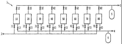
[0023] Figure 1 is a flow schematic for a PSA system 1 of the present
invention having a
pressurized feed gas manifold 2, a pressurized product manifold 3, and a low-
pressure
raffinate manifold 4. Product manifold 3 is provided with a product surge tank
5 while
raffinate manifold 4 is provided with raffinate surge tank 6. In the process
of the present
invention, at least a first PSA module 10 and a second PSA module 20 are
connected to the
feed, product and raffinate manifolds. In the embodiment of Figure 1, eight
PSA modules 10,
20, 30, 40, 50, 60, 70 and 80 are operated in parallel. Any number of parallel
modules may
be employed in the process of the present invention, and the choice of eight
modules is
adopted only as an example.
[0024] The PSA modules are connected to the feed manifold 2 by their
respective isolation
valves 11, 21, 31, 41, 51, 61, 71, and 81. The PSA modules are connected to
the product
manifold 3 by their respective isolation valves 12, 22, 32, 42, 52, 62, 72,
and 82. The PSA
modules are connected to the raffinate manifold 4 by their respective valves
13, 23, 33, 43,
53, 63, 73, and 83. When all of these valves are in their open positions,
every PSA module is
fluidly connected in parallel. Individual PSA modules may be isolated from the
fluid
manifolds by closing the valves connecting that module to the manifolds. For
instance,
module 20 may be isolated by closing valves 21, 22 and 23. Once a module is
isolated, it is
possible to conduct maintenance on that module while the rest of the installed
modules are
still in production. If module 20 was found to have a defective or
malfunctioning component,
5
CA 02809165 2013-03-08
it could be isolated from the PSA process manifolds 2, 3 and 4 by closing the
valves 21, 22
and 23, and then maintenance can be carried out. PSA modules 10, 30, 40, 50,
60, 70 and 80
would continue to operate as usual. The maximum system capacity would be
7/8ths of the
original capacity. This slight reduction in overall capacity may be addressed
by operating the
remaining PSA modules at a higher operating cycle frequency, or may be managed
by
designing additional capacity into the overall system such that no significant
performance
degradation is experienced when running at slightly elevated flowrate
conditions.
[0025] Figure 2 illustrates another advantage of the PSA process of the
present invention.
Figure 2 is a graph showing low-pressure raffinate flowrate versus time for
four different
operating strategies for the PSA system 1 of Figure 1. These traces are for a
three-
equalization, seven bed PSA after the process of U.S. Patent No. 6,699,307
but.
the effect is similar for any PSA cycle. PSA cycles using less than three
equalizations would
show even more pronounced pulsation in the raffinate flowrate.
[0026] If the PSA system is operated with every module synchronized to run
their
individual PSA cycles in phase, the flow pulsations are the same as operating
a single process
train, and the total flowrate varies between less than 1,000 units and over
17,000 units, a
factor of 17:1. In the process of the present invention, the array of PSA
modules is operated
out of phase, such that periods of raffinate gas generation are offset from
one another. In a
first embodiment of the present invention, the eight modules of the PSA system
are operated
in two groups of four; with each group operated 180 degrees out of phase with
one another.
Figure 2 shows that this results in the raffinate flowrate varying between
roughly 1,500 and
9,000 units. This is a ratio of about 6:1, which is nearly three times less
than was the case
with the prior art method of operating a single process train, or operating
many modules both
in parallel and in phase. In this first embodiment, each group uses half of
the total available
modules. For the example of an eight module system, this results in four
groups of modules.
6
CA 02809165 2013-03-08
If one module fails and must be isolated for repair, the system retains 7/8ths
capacity, but the
raffinate flowrate waveform would change due to the asymmetric nature of the
two groups of
vessels. The flowrate through the remaining three vessels in the group would
be increased as
much as 33% during some process steps, a factor which must be considered to
prevent
fluidization of the adsorbents and/or fluid shocks in the piping and/or
valving systems.
[0027] In alternative configuration of the present invention, the modules are
separated into
four groups and are each operated 90 degrees out of phase. Figure 2 shows that
the resulting
raffinate flowrate varies between about 2,000 and 6,000, a ratio of about 3:1.
This is roughly
half the flowrate variation experienced in the first embodiment where two
groups of modules
operate 180 degrees out of phase, and one sixth the variation of the prior art
methods.
Although this flowrate variation reduction is impressive, it reduces the
number of modules
per group to two for the example of an eight module system. If one module must
be repaired,
the change in flowrate for the other module in the group would be 100% during
some cycle
steps, a factor to be considered in designing the vessels and their
interconnecting valves and
flow conduits.
[0028] In a further alternative configuration of the present invention, eight
groups of
modules are employed with their cycles offset by 45 degrees. This yields only
a modest
decrease in flowrate pulsation compared to four groups, and results in even
larger changes in
flowrate should a module require repair. In the example of the eight module
system, each
module would operate independently, for instance.
[0029] Although even-numbered groups were described above and shown in Figure
2, odd
numbers of groups are also feasible. In fact, any number of groups is
feasible. Further, any
number of modules can also be used to yield any number of modules per group.
The
embodiments discussed above assume that the groups operate 180, 90 and 45
degrees out of
phase. For a given PSA cycle for each module, different phasing may be
desirable to
7
CA 02809165 2013-03-08
minimize flow variations of the product, the raffinate or both.
[0030] It is preferable that each group have the same number of vessels in
order to
minimize flow variations for the entire system as well as flowrate variations
through any
given module in order to avoid the problems of adsorbent fluidization and
fluid shocks. The
balance between the number of groups and the number of modules per group must
be
optimized for each application of the present invention. In an application
where minimized
downtime for the connected equipment is the highest priority, a system with
fewer groups
each having a greater number of modules in parallel is preferred. In a system
where
reliability is of less importance than flowrate pulsation, a greater number of
groups with
fewer modules will be desired.
[0031] Figure 3a illustrates a preferred apparatus for the PSA module of the
present
invention. The PSA module 100 has seven adsorbent chambers 101 arrayed between
a feed
manifold 102 and a product manifold 103. The pressurized adsorbent chambers
are held in a
fixed relationship with the manifolds via tie bolts 104. Both the feed and
product manifolds
are provided with a plurality of valves 105, which are used to execute the PSA
cycle.
[0032] The PSA module 100 illustrated in Figure 3a is an especially-preferred
embodiment
for executing the seven adsorbent vessel, three pressure equalization cycle
described in U.S.
Patent No. 6,699,307. The apparatus of the present invention may also
preferably
be used to execute other cycles disclosed therein, as well as other PSA cycles
of the related
art.
[0033] Side section view 3b shows a single adsorbent chamber 101 provided with
an
adsorbent mass 110. The adsorbent mass may be a single type of adsorbent, or
may be made
up of mixtures of adsorbent or distinct layers of adsorbent. The choice of
adsorbent mass
composition and size is dictated by the process flow conditions, the
separation of interest and
the PSA cycle, and does not limit the present invention in any way. The
adsorbent chamber
8
CA 02809165 2013-03-08
is sealingly connected to the inlet manifold 102 and the outlet manifold 103.
[0034] Figure 4 shows an exploded section view of the adsorbent chamber and
manifolds
of Figure 3b. The adsorbent chamber 101 is advantageously mated to a sealing
boss 111
provided on both the inlet and outlet manifolds. These are shown as identical
features in the
figure, but may be differently shaped if desired. Each sealing boss is
provided with at least
one sealing member 112 which affects the fluid seal between the adsorbent
chamber and the
=
manifold. Although preferred internal radial sealing features are shown in
Figure 4,
compression seals or external radial seals may be provided. Neither the seals,
nor the sealing
boss affects a rigid structural joint between the manifolds and the adsorbent
chamber.
[0035] In PSA adsorbent chambers of the related art, the adsorbent chamber is
fixed in
rigid structural relation to an end flange feature or manifold. Such rigid
connections
undesirably give rise to localized bending stresses. Due to the cyclic nature
of the stress state
in a PSA apparatus, this bending moment can undesirably give rise to
substantial problems
with premature fatigue failure of the apparatus. Such premature failure is
especially
dramatically accelerated in the case of hydrogen PSA, as hydrogen
embrittlement can affect
many metallic construction materials. Thus, the non-structural sealing feature
of the present
invention is especially desirable as it facilitates the use of far thinner
structural elements for
equivalent fatigue life. Further, since the structural connection between the
manifolds which
resists the pressure forces is not in contact with the fluid being purified,
high-strength
materials which are otherwise particularly susceptible to hydrogen
embrittlement may be
used. For instance, hardened steel may be used for the tie bolts 104, a
material unacceptable
in related art construction for hydrogen systems.
[0036] Another advantage of the sealing apparatus of the present invention is
that different
materials may be used to manufacture the adsorbent chamber, manifolds and tie
bolt features.
Thus, a material that has good strength but little stiffness could be used for
the adsorbent
9
CA 02809165 2013-03-08
chambers, such as fiberglass-reinforced plastic, while a stiff material with
less strength may
be used for the manifolds, such as aluminum or closed-cell polymer foam.
Finally, a third
material can be used for the tie bolts. This freedom to optimize each material
individually
facilitates potentially dramatic decreases in weight and/or materials cost
when required for a
particular application.
[0037] Figure 4 shows that the sealing bosses 111 are provided with a concave
internal
form to aid in flow distribution from the outlet and inlet radial flow
distributors 113 and 114.
These may be a separate component as shown in Figure 4, or may be formed
integrally with
the manifold. The radial flow distributor is in fluid communication with a
fluid channel 115
in the inlet manifold and fluid channel 116 in the outlet manifold. Flowing
fluid from the
channel 115 through the flow distributor 114 communicates with a chamber 120.
The
chamber is defined by the concave feature of the sealing boss as well as the
adsorbent retainer
plate 122, which is supported by a snap ring 123. The PSA apparatus of Figures
3 and 4 is
shown for the case with the inlet manifold on the bottom of the apparatus and
the outlet
manifold on the top. If the apparatus is mounted in the opposite direction,
the snap ring 123
would be on the other side of the retainer plate.
[0038] The retainer plate 122 may advantageously be supplied with a fine mesh
layer 124
to retain small diameter adsorbent particles. This mesh layer may be made from
wire mesh,
woven or non-woven polymer, glass or other fabric. The mesh layer 124 and the
retainer
plate 122 are preferably assembled with a radial seal ring 125 which holds
them together for
assembly and provides a radial seal to present bypassing of fluid or
particles. Although this
composite retainer assembly is preferred, other adsorbent support means may be
used with
equal success, such as metal, polymer or ceramic foams with an open structure,
nonwoven
mats, or other means apparent to one skilled in the art.
[0039] The outlet manifold is preferably supplied with a similar retainer
plate assembly,
10
CA 02809165 2013-03-08
except that the snap ring 123 is positioned to hold the retainer plate from
above. It is most
preferable to supply an elastic layer 130 between the upper retainer plate and
the adsorbent.
This elastic layer is then held in compression by the outlet end retainer
plate assembly, and
exerts a compressive load on the adsorbent mass 131. Preferred elastic
materials also serve a
filtration function to exclude fluidized dust particles from entering the
manifolds. Examples
of preferred materials are reticulated polymer foam, woven or= non-woven
elastomer mat, or
elastomer-impregnated mat such as those made from natural fibers such as
coconut fiber. If
desired, an elastic element may also be provided at the inlet, or bottom end
of the adsorbent
chamber.
[00401 The inlet manifold 102 is provided with a feed valve 135 and a waste
valve 136.
These valves mate with valve seats formed into the manifold. Inlet valve 135
communicates
between parallel feed flow channel 137 and adsorbent chamber 101 through the
channel 115
and the radial flow distributor 114. Feed flow channel 137 communicates with
all of the
adsorbent chambers in the apparatus through their respective valves. It may be
appreciated
from Figure 4, which shows the valve 135 in its closed position, that flow
through feed
channel 137 between adsorbent chambers in the apparatus is not materially-
impeded by the
valve 135, whether it is in the open or closed position. This feature may be
ensured by
providing a flow channel 137 of sufficient cross-sectional area to ensure the
ready flow
through the channel, which is critical to the implementation of the PSA cycles
of U.S.
Patent No. 6,699,307. The waste valve 136 likewise communicates with a
parallel waste flow channel 138, which is in fluid communication with all of
the adsorbent
chambers 101 of the apparatus through their respective valves. The figures
show a manifold
that is machined, and the channel features 115 are formed by drilling. Thus,
plugs 140 are
provided to seal the ends of the channel 115. If the manifold is formed by a
net shape process
such as casting, plugs 140 are not required. Likewise, the plugs could be
replaced with
11
CA 02809165 2013-03-08
sensors, safety relief valves or other appurtenances. Further, the flow
channels 115 and/or
137 can be provided with additional features to provide connections for
sensors, sample
withdrawal, etc. The provision of such additional features does not limit the
present
invention in any way.
[00411 The outlet manifold 103 is similarly provided with product valve 141,
equalization
valve 142 and equalization valve 143. These valves communicate with product
conduit 144,
first equalization conduit 145 and second equalization conduit 146. Each of
these conduits is
in fluid connection with each of the adsorbent chambers of the PSA apparatus
through the
respective valves for each chamber. The apparatus shown is for the especially-
preferred PSA
cycle with seven adsorbent vessels and three pressure equalizations of U.S.
Patent No. 6,699,307 by
the present inventor. Other PSA cycles would use different numbers of valves
and conduits.
For instance, the six or five adsorbent chamber cycles of the above-named
application would
omit one of the equalization conduits and valves depicted in the figures for
each adsorbent
chamber.
10042] The equalization conduit 145 is additionally provided with porous flow
restriction
element 147 which is retained by retaining ring 148. Alternatively, the
retaining ring may be
used to secure a flow control orifice plate. Other elements such as check
valves or flow
control valves may also be provided. Such features may be provided only for
one parallel
flow channel as shown here, or for more than one channel.
[0043] The apparatus depicted here uses preferred piston valves as described
in U.S.
.U.S. Patent No. 6,755,895 ' with air actuation. Alternatively, the valves may
be
solenoid operated, hydraulically-operated or mechanically-operated via a
mechanical drive
system such as a camshaft. The choice of valve actuation does not limit the
present
invention, and does not detract from the advantages thereof. Further, the
apparatus depicted
uses all valves of a single size. Valves of varying sizes and types may be
advantageously
12
CA 02809165 2013-03-08
combined in the present apparatus to achieve desired combination of flow
properties.
Further, although the most-preferred apparatus employing parallel flow
conduits is depicted,
traditional PSA cycle not employing parallel flow conduits may also be
executed by
providing the required internal flow features.
10044] The manifolds of the present invention may be made by machining from
solid stock,
or by machining from a near net shape part made by casting or by joining
together layers of
material by brazing, soldering or adhesive bonding. Further, the manifolds may
be made as a
monolithic assembly, or be fashioned in a number of pieces held together by
fasteners or
other means and sealed by means of fluid seals such as gaskets. The choice of
manufacturing
technique does not limit the advantages of the present invention.
[0045] Figure 5a shows a second embodiment of the PSA apparatus of the present
invention. The tie rods of the first embodiment are omitted, and are replaced
by structural
panels 200 and 201. These panels are secured to the manifolds 102 and 103 by
fasteners 202.
An example of a preferred fastener being a machine screw, although other types
of fasteners
may be employed. Alternatively, the joining means between the structural
panels and the
manifolds may be via an adhesive bond, brazing, soldering or welding. Indeed,
any load-
bearing connection joining the manifolds to the structural panels may be
advantageously
used. This connection allows the pressure load separating the two manifolds to
be borne by
the structural panels in a state of substantially-pure tensile stress. Design
of a flat panel in
tension is straightforward, and common construction materials such as metallic
or polymer
sheet excel in bearing tensile load. The use of structural panels
advantageously distributes
the pressure load along the boundary of the manifolds, thus mitigating the
local stresses
engendered by the tie bolts 104 of the first embodiment.
[0046] Figure 5a also shows similar panels 203 and 204 which serve as
structural supports
for the module. Again, these are advantageously mechanically-attached to the
manifold using
13
CA 02809165 2013-03-08
means that are adequate to support the mechanical loadings imposed by the
module weight,
as well as any additional loads posed by wind, seismic action, shipping loads,
service loads,
etc. Such structural panels may advantageously be provided with
interconnecting features
205 in order to create a stronger and stiffer support structure. Further,
mounting features 206
may be provided to allow secure connection between the support panels and the
module
foundation. Access cut-outs 207 may optionally be supplied in the support
panels in order to
facilitate maintenance and inspection of the valves. The module may also be
advantageously
provided with a top cover 208 which provides weather protection to the valves.
This cover
may be provided with valve actuation port 209 to permit installation of the
required valve
actuation means, whether they are pneumatic or electrical lines.
Alternatively, the valve
control apparatus may be advantageously located inside the valve cover 208,
protected from .
the weather. In this case, only a main electrical and/or pneumatic supply line
would be
required.
[0047] Figure 5b shows an assembled view of the second embodiment of the PSA
apparatus 210. It is readily apparent that if the structural panels of the
present invention are
applied on all sides of the module, they provide a substantial degree of
protection against
accidental damage to the adsorbent chambers. Such damage can easily occur
during shipping
and installation. The valves are also well-protected. It is, therefore,
apparent that it may be
advantageous in some situations to combine the panels of the second embodiment
with the tie
bolts of the first embodiment. A prime example being the case where local
pressure vessel
laws do not allow the structural panels of the present invention, but permit
the tie bolts.
Further, temporary panels whose only function is protection during shiprnent
may be
provided which attach using means similar to those used for the structural
panels. For special
applications where ease of access to the valves or adsorbent chambers is
required, the PSA
apparatus may be provided with panels on only two or three sides provided that
the structural
14
CA 02809165 2013-03-08
strength of the remaining panels is suitably increased.
[0048] The panels of the PSA apparatus of the present invention advantageously
reduce the
complexity of assembly. They also facilitate a reduction in weight, as they
reduce localized
stresses associated with the tie bolts. These advantages are combined with
improved
shipping and handling durability, weather protection, and increased aesthetics
compared to
prior art methods.
[0049] Figure 6 is a perspective view of the PSA system of the present
invention
implemented using the preferred PSA apparatus of the present invention. The
elements
described in Figure 1 are indicated by their numbers in Figure 6. The site
footprint of the
PSA system may be reduced significantly if no space is provided between the
modules for
maintenance access. Using the preferred apparatus, this may be accomplished as
all
maintenance tasks may be executed with access only to the top and bottom of
the modules.
The physical layout of the modules is not limiting, and any mechanical layout
which
accomplishes the fluid interconnections of the present invention will yield
the special
advantages of the present invention.
[0050] The present invention provides numerous advantages. For example, the
present
invention provides a pressure swing adsorption apparatus that does not require
fluid
connectors between adsorbent vessels. Additionally, the present invention
provides a
pressure swing adsorption apparatus that does not require welding for
construction. The
present invention also provides a pressure swing adsorption apparatus that has
minimal empty
volume. Furthermore, the present invention provides a pressure swing
adsorption apparatus
that does not require structural support for the adsorbent vessels. While
these structural
advantages may be useful in certain circumstances, such structural features
are not required
by the present invention.
[0051] It should be noted that the exemplary embodiments depicted and
described herein
15
CA 02809165 2013-03-08
= set forth the preferred embodiments of the present invention, and are not
meant to limit the
scope of the claims hereto in any way.
[0052] Numerous modifications and variations of the present invention are
possible in light
of the above teachings. It is therefore to be understood that, within the
scope of the appended -
claims, the invention may be practiced otherwise than as specifically
described herein.
16