Note: Descriptions are shown in the official language in which they were submitted.
CA 02809191 2013-02-22
1
Device for Producing Processed Cheese Portions
The invention relates to a device for producing processed cheese portions,
comprising a plurality of modules disposed successively in the direction of
production, in which the processed cheese is shaped into a strip, cooled and
divided
into portions, wherein the modules define a production space through which the
processed cheese passes during production of the processed cheese portions.
In the production of a foodstuff, constant care must be taken to prevent
contamination of the product as it passes through the production system.
Foodstuffs
that have come in contact with germs or grime are a risk to the manufacturer
that
cannot be underestimated. These foodstuffs spoil before expiration of the
intended
shelf life and must be removed from commerce; in addition, they can cause
health
problems for the consumer if consumed unawares.
Therefore, the production system must be absolutely germ-free in order to
produce a
hygienically flawless foodstuff. By necessity, production must be interrupted
regularly
in order to restore the production system to a germ-free state. Valuable
production
time is lost to cleaning, which is somewhat complicated, particularly when
individual
components of the system must be removed for this purpose.
In order to minimize the introduction of grime, the production system should
be
installed in a production space that is as hygienically flawless as possible.
In order to
perform production in a manner that is truely bacteriologically safe, the
system itself
must be cleaned and a clean-room environment is required. Therefore, the
production environment has a substantial influence on the frequency of the
cleaning
cycles. The requirement to maintain entire rooms germ-free is very difficult
to
implement. This limits the usability of large and open production systems that
are
known from the production of processed cheese.
The amount of cleaning effort required can be reduced by keeping the system
parts
that must remain germ-free separate from the rest of the production hall or
the
system. For example, so-called aseptic filling machines are used in automated
beverage bottling. An aseptic filling machine is the actual filling area,
which is
CA 02809191 2013-02-22
2
separated from the rest of the filling system via an enclosure. The enclosure
defines
an enclosed production space in the immediate vicinity of the filling area,
which is
separated from the rest of the system. The production space encloses and
protects
the filling area, and the desired germ-free state is attained via regular
cleaning of the
outer and inner surfaces thereof.
The effort required to maintain the germ-free state of a production space
enclosed in
this manner is substantially less compared to that of a filling area that is
left open.
The cleaning of a production space enclosed in that manner can be carried out,
for
example, via cleaning-in-place (CIP) using cleaning systems fixedly installed
in the
enclosure.
Such enclosures are not used in the production of processed cheese portions.
The
main reason therefor is that a plurality of working steps is required to
process
processed cheese, all of which require a hygienically flawless environment.
The
production systems that are used are also substantially larger and have a
highly
complicated design as a narrowly limited, easily protected filling area for
beverage
bottles. Instead of flowing through closed and easily cleaned pipelines, the
processed cheese to be processed is guided openly across long distances while
the
strand is formed. In so doing, the processed cheese mass comes into contact,
via
large areas, with the rollers and belts of the system. In order to ensure a
flawless
hygienic quality of the processed cheese that is produced, a subregion of the
system
as well as the entire production strand would have to be enclosed.
Moreover, the production of processed cheese portions requires repeated
intervention by operating personnel. Therefore, the system must always be
accessible. In addition, an enclosure should be designed such that cleaning
and
rinsing agents sprayed in the production space during a CIP are prevented from
spraying out of there. However, a sealed enclosure intended for ensuring the
germ-
free state is not easily opened, nor does said enclosure allow direct access
to all the
relevant system parts.
The problem addressed by the present application is therefore that of
simplifying the
production of hygienically flawless processed cheese portions.
CA 02809191 2015-02-04
3
This problem may be solved by one or more aspects of the present invention.
According to an aspect of the present invention there is provided a device for
producing processed cheese portions, comprising a plurality of modules
disposed
successively in a direction of production, in which the processed cheese is
formed into
a strip, cooled and divided into portions, wherein the modules define a
production
space through which processed cheese passes during production of the processed
cheese portions, wherein a spray-proof encapsulation encloses the production
space,
wherein the encapsulation comprises a frame structure and a plurality of sheet
metal
elements, which are detachably connected to the frame structure, and wherein a
sealing tube is disposed between a sheet metal element which is one of the
plurality
of sheet metal elements and the region of the frame structure opposite thereto
and
encircles the sheet metal element or the region of the frame structure
opposite thereto.
In some embodiments, the sealing tube encircling the sheet metal element or
the
region of the frame structure opposite thereto is designed in the manner of a
labyrinth
seal.
In some embodiments, the sheet metal element comprises external bent edges,
wherein the bent edges form a receptacle for the sealing tube.
In some embodiments, the device further comprises a sheet metal element that
is
swivellably held on the frame structure, wherein parts of the frame structure
opposite
the sheet metal element that is swivellably held on the frame structure
comprise a
circumferential web, which forms a receptacle for the sealing tube.
In some embodiments, the production space is connected to an air treatment
system,
by way of which treated air can be introduced into the production space.
In some embodiments, the air treatment system comprises a module for filtering
and/or
drying and/or cooling the air that is introduced into the production space.
In some embodiments, the air intake of the air treatment system is connected
to the
production space such that the air flowing through the production space is
conducted
in a closed circuit.
CA 02809191 2015-02-04
3a
In some embodiments, the air treatment system is integrated into the
encapsulation of
the production space.
A fundamental idea of the invention is to enclose the production space with a
spray-
proof encapsulation, wherein the encapsulation comprises a frame structure and
a
plurality of sheet metal elements, which are detachably connected to the frame
structure, and wherein a sealing tube is disposed between a sheet metal
element and
the region of the frame structure opposite thereto and encircles the sheet
metal
element or the region of the frame structure opposite thereto.
The encircling sealing tube is disposed such that, when the sheet metal
element is
closed, said sealing tube is pressed between the frame structure and the sheet
metal
element via application of external force. The hollow sealing tube deforms
elastically,
and therefore the gap between the sheet metal element and the frame structure
remains completely closed even under unfavorable conditions, such as the
occurrence of vibrations during operation, for example. The production system
enclosed in this manner is therefore securely protected against the
introduction of
grime or bacterial contamination from the outside.
The encircling sealing tube is flexible enough to compensate for potential
manufacturing tolerances of the frame structure. Therefore, the frame
structure that
is provided is not subject to any special requirements, but rather can be
assembled
from standardized profiles having low tolerances, which are easy to
manufacture and
assemble. The standardization also makes it easy to adapt the encapsulation to
different types of such production systems.
Due to the sheet metal elements that are detachably connected to the frame
structure, the individual system elements are easy to access, but the sheet
metal
element to be opened for this purpose can always be tightly reclosed. Every
time the
sheet metal elements are closed, the sealing tube is elastically deformed once
more
and the sealing effect of the tubular seal is restored. The encircling tubular
seal
provides a high degree of sealing, and therefore the production space is
reliably
sealed. Additional sealing elements can be omitted. The encapsulation
according to
the invention therefore fulfills all the hygienic requirements for a germ-free
production
CA 02809191 2013-02-22
4
space. Moreover, the encircling tubular seal, due to the uncomplicated design
and
installation thereof, allows for simple inspection and cleaning of the seal
and for easy
replacement thereof.
In particular, the encircling sealing tube is designed as one piece, thereby
reducing
the seams, which impair the seal integrity. The seams open, in particular,
during a
temperature-induced expansion of the encapsulation. Depending on the type of
processed cheese, the processed cheese mass is heated before shaping to
temperatures that clearly exceed 60 Celsius. The tubular seal formed as one
piece
improves the functional reliability of the seal across a large temperature
range.
In order to permit viewing of individual system parts, the sheet metal
elements can
also be equipped with an installed observation window. This allows for high
transparency even when the encapsulation is closed and, therefore, allows for
constant visual inspection of the system and the functions thereof during
operation.
Preferably, the sealing tube encircling the sheet metal element or the region
of the
frame structure opposite thereto is designed in the manner of a labyrinth
seal. This
sealing tube comprises, on the surface thereof, a plurality of longitudinally
extending
sealing lips or lamellas, which, when the sheet metal element is closed, bear
individually against the pressed-on contact surface and each impart a sealing
effect.
In particular, a fluid located on the tubular seal in the horizontally
extending part of
the circumferential region is effectively held back. The thusly designed
sealing tube
also withstands CIP-cleaning carried out at high pressures, even if a jet of
cleaning
or rinsing agent strikes the seal directly while the system is being sprayed.
Therefore, the production system enclosed according to the invention permits
the
production space to be cleaned easily and quickly, and there is no need to
remove
components of the system. In addition, fluids spraying out of the
encapsulation,
which causes contamination of the exterior environment, is effectively
prevented.
In a further preferred embodiment, the sheet metal element comprises external
bent
edges, wherein the bent edges form a receptacle for the sealing tube. If the
sheet
metal elements themselves form the receptacle for the sealing tube, sheet
metal
elements of any shape and size can be used without the need to make changes to
CA 02809191 2013-02-22
the sealing receptacle. The bent edge extending on the edges of the sheet
metal
element forms a receptacle that is precisely matched to the dimensions of the
particular sheet metal element. Therefore, the sheet metal element always
forms its
own sealing receptacle. The step of separately adapting the sealing receptacle
if the
shape of the sheet metal element is changed is eliminated. In addition, the
external
bent edges stabilize and stiffen the sheet metal elements.
Preferably, a sheet metal element is swivellably held on the frame structure,
and the
parts of the frame structure opposite the sheet metal element that is
swivellably held
on the frame structure comprise a circumferential web, which forms a
receptacle for
the sealing tube. A sheet metal element that is swivellably mounted on the
frame
structure is particularly easy to open and allows rapid access to the system
parts
located behind it. The sheet metal element, which is swivelled to be opened,
is held
further from the frame structure and, once work has been completed, can be
closed
simply by being swiveled back. The sealing tube is carried by a web that
entirely
encircles the parts of the frame structure opposite the sheet metal element.
The
sealing tube, which has been inserted on the web, in particular, therefore
reliably
seals the closed sheet metal element.
In a particularly preferred embodiment, the production space is connected to
an air
treatment system, by way of which treated air can be introduced into the
production
space. This embodiment makes it possible to use the encapsulated production
space largely independently of the air quality of the surrounding premises.
The air
treatment system supplies the encapsulated production area with a separate
atmosphere, so to speak, which is oriented toward germ-free production. The
effort
required to keep entire production halls germ-free or nearly germ-free is
eliminated.
Advantageously, a slight overpressure is generated in the interior of the
encapsulation, thereby preventing air from entering the production space from
the
outside.
Preferably, the air treatment system comprises a module for filtering and/or
drying
and/or cooling the air introduced into the production space. The corresponding
modules make it possible to create a climate within the production space that
is
optimal for processed cheese production. A module for clean room filtering
reduces
CA 02809191 2015-02-04
6
the germ count of the air introduced into the production space. Cooling and/or
drying
the air prevents condensation water from forming in the production space and
suppresses the reproduction rate of any germs that may be present.
In a further preferred embodiment, the air intake of the air treatment system
is
connected to the production space such that the air flowing through the
production
space is conducted in a closed circuit. Therefore, the treated air is
circulated.
Reusing the air in this manner reduces the amount of energy required for the
treatment.
Preferably, the air treatment system is integrated into the encapsulation of
the
production space. In this case, a separate encapsulation of the air treatment
system
is eliminated, thereby simplifying the design of the production system. The
integration also allows the air treatment system to be integrated into the
CIP.
Therefore, CIP cleaning of the system comprises all the components that are
essential to maintain a germ-free state of the production space.
Various aspects of the device according to the invention are explained, as
examples,
by reference to the following figures. Shown are
Figure 1: a top view of two sheet metal elements mounted on the frame
structure;
Figure 2: a sectional drawing along the line A-A of figure 1;
Figure 3: a sectional drawing through the region of figure 1 labelled "B";
Figures 4 and 5: an exemplary embodiment of an air treatment system according
to
the example;
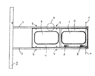
Figure 1 shows a part of a frame structure having two vertical supports 1, 2,
which
are oriented parallel to one another. The two supports 1, 2 are held by a
horizontal
base support 3 of the frame structure. Two sheet metal elements 4, 5, which
are
mounted on the supports 1, 2, are disposed between the supports 1, 2. Both
sheet
metal elements comprise a central observation window 6, which permits
inspection
CA 02809191 2015-02-04
7
of the production system located behind said observation window without the
need to
open the encapsulation. The sheet metal element 4 is detachably connected to
the
supports 1, 2. Four pins 7 routed into the supports 1, 2, namely two per
support, hold
the sheet metal element 4 on the frame structure. A tubular seal held in an
outer
bent edges of the sheet metal element is elastically deformed between the
sheet
metal element 4 and the frame structure. The tubular seal is located on the
two
supports 1 and 2, and on a support that connects said supports, if present.
The
circumferential tubular seal seals the sheet metal element 4 completely with
respect
to the frame structure.
The sheet metal element 5 is swivellably mounted on the support 1 and, in the
closed state, is sealed with respect to the supports 1 and 2 and the support,
which
is present here and connects said supports 1,2. In the view shown in figure 1,
the
transversely oriented support is hidden by the sheet metal element 5. Two
locks 8,
which can be locked on the support 2, hold the swivellable sheet metal element
5 in
the closed position thereof. The sealing of the sheet metal element 5 is
explained in
greater detail in figure 2.
Figure 2 shows a sectional drawing along the line A A of figure 1. The sheet
metal
element 5, which is held by a non-illustrated hinge and which comprises an
observation window 9, is shown in figure 2 in an angled, i.e. slightly opened
position.
The supports 1, 2 of the frame structure have a hollow profile, from which a
web 10 protrudes for sealing the swivellably mounted sheet metal elements. A
hollow tubular seal 11 is slid onto the web 10. The web continues on the
transversely
oriented support, which is not shown here, and therefore said web completely
encircles the opening of the frame structure formed between the supports on
the
inner side of the frame structure. If the sheet metal element 5 is swivelled
toward the
frame structure, the sealing tube 11 is elastically deformed between the web
10 and
the outer edge of the sheet metal element 5 and completely seals the gap
between
the frame structure and the sheet metal element 5. External bent edges 12
facing
away from the frame structure stabilize the sheet metal element and ensure
uniform
contact pressure of the sheet metal element against the sealing tube 11.
Figure 3 shows a sectional drawing through the region of figure 1 labelled
"B". A
CA 02809191 2013-02-22
8
hollow tubular seal 13 bears against the hollow support 1. The sheet metal
element 4
has an angled bent edge 15 on the outer edge thereof, which forms a seal
receptacle 18 for the sealing tube 13 encircling the sheet metal element 4.
If a transversely extending support is not provided between the successive
sheet
metal elements 4 and 5, as shown in figure 1, the swivellably mounted sheet
metal
element 5 overlaps the detachably fastened sheet metal element 4. In the
region of
overlap, the two sheet metal elements form a fold, which extends underneath
both
said sheet metal elements. The metal webs, which are designed in the manner of
a
labyrinth seal, prevent fluid from escaping from the enclosure, and so an
additional
seal can be omitted.
Figures 4 and 5 show an air treatment system 17 having inflowing 18 and
outflowing
19 air conduction. The enclosed air treatment system 17 comprises a plurality
of
modules, in which the air conducted therethrough is dried and held at a steady
temperature, and comprises a collecting device for condensation water that is
discharged.