Note: Descriptions are shown in the official language in which they were submitted.
CA 02809236 2016-09-08
. .
PROCESS TO REMOVE IMPURITIES FROM TRIACYLGLYCEROL OIL
DESCRIPTION
BACKGROUND OF THE INVENTION
[Para 1] The invention generally relates to methods of triacylglycerol
oil
refining and is based on using flow-through hydrodynamic cavitation. The
invention utilizes energy released upon the implosion of cavitation bubbles to
purify oils and improve the commercial value of collected by-products. More
particularly, the present invention relates to lowering the levels of sterol
glucosides (SGs) and acylated sterol glucosides (ASGs) and enzyme-
hydrolyzable phospholipids which can be followed by biodiesel production
through transesterification. The residual concentrates obtained from the
invention can be used as blood cholesterol lowering food additives, in
pharmaceuticals' production or for other purposes. The invention finds
application in biofuel, chemical, food, pharmaceutical and other industries.
[Para 2] Crude vegetable oils are comprised mostly of triacylglycerols
(TAG)
and contain impurities such as phospholipids (phosphatides), free fatty acids
(FFA), off-flavor compounds, carotenes, chlorophyll and other pigments, waxes,
aluminum, calcium, copper, iron, magnesium and other metals and
phytosterols. The impurities negatively affect the quality of oil and oil-
derived
products and must be removed before use.
1
CA 02809236 2016-09-08
[Para 3] The crude oil can be produced by solvent extraction or by pressing
seeds either with heating or without it. The hot pressing affords the better
yield
but results in oil deterioration and the accumulation of non-hydratable
phosphatides (NHP), for example calcium and magnesium salts of phosphatidic
acid (PA) and phosphatidyl ethanolamine (PE) due to the action of enzymes that
are active at 57-85 C. PE can be hydrated if it has a net charge. PA has a
glycerol backbone usually with a saturated fatty acid, an unsaturated acid,
and
a phosphate group attached to carbon 1,2 and 3, correspondingly. To assure a
high quality of oil, oil producers avoid exposing seed to temperatures around
55 C-80 C and treat them with steam at approximately 150 C to deactivate
phospholipases and lower PA salt level by 25-50% (Cmolik and Pokorny, 2000;
Gunstone etal., 2007).
[Para 4] Oil refining methods depend on the type of oil and usually
comprises degumming, bleaching and deodorization. Degumming is the
removal of phosphorus present in the form of hydratable and non-hydratable
phosphatides. Water degumming provides refined oil with a phosphorus
concentration greater than 200 ppm and can be followed by alkali refining,
bleaching and deodorizing or by acid degumming, dry degumming and physical
refining or by enzymatic degumming (Clausen, 2001), bleaching and physical
refining. There are numerous variations of oil refining methods, depending on
the quality of oil and other conditions. In addition, oil can be hydrogenated
to
afford a stable product.
2
CA 02809236 2016-09-08
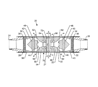
. .
[Para 5] Each refining step results in some loss of oil. (Racicot and
Handel,
1982; Cvengros, 1995; Cmolik and Pokorny, 2000) The oil yield can be
increased by using enzymes instead of chemical reagents. For example,
phospholipase C hydrolyzes phosphatidylcholine (PC), liberating the water-
soluble phosphate ester of choline and diacylglycerol (DAG). The conversion of
phospholipids to DAG increases the oil yield due to the accumulation of DAG in
the oil phase and minimal entrapment of neutral oil in gums comprised of
hydrated lecithin. PC is converted by phospholipases Al and A2 to
lysophosphatidylcholine and FFA. Lipid acyltransferase (LAT) catalyzes PC
breakdown to lysophosphatidylcholine and FFA, which can form esters with the
free sterols present in oil. Accordingly, PE is converted by phospholipases Al
and A2 and LAT to lysophosphatidylethanolamine (LPE) and FFA or steryl esters.
LPE is a plant growth regulator that can be isolated as a valuable by-product.
Phospholipase C catalyses the hydrolysis of PE to ethanolamine-phosphate and
DAG. Phosphatidylinositol (PI) can be hydrated over a wide pH range and is
converted by phospholipases Al and A2 and LAT to lysophosphatidylinositol.
However, PI is not hydrolyzed by phospholipase C. Phospholipases Al and A2
and LAT convert alkali salts of PA to lysophosphatidic acid salts. Alkali
salts of
PA are not affected by phospholipase C.
[Para 61 Since phospholipases Al and A2 and LAT are soluble in water,
they
act on the phosphatides located at the oil/water interface. As a consequence,
the enzymatic degumming requires long-duration, high-shear agitation to
sustain the large oil/water surface area and high mass transfer rates and
slows
3
CA 02809236 2016-09-08
. .
down with the coalescence of water-in--oil dispersion. Oil producers do not
use
emulsifiers for the stabilization of dispersions on an industrial scale
because of
their high cost.
[Para 7] SGs are sterol derivatives, in which a carbohydrate unit
(arabinose,
glucose, etc.) is linked to the hydroxyl group of campesterol, brassicasterol,
dihydrositosterol, sitosterol, stigmasterol or other sterols with an ether
bond. In
ASGs, which are very soluble in vegetable oils, the carbohydrate 6-carbon is
esterified with a long chain fatty acid. Phytosterols are abundant in plants
and
can be readily isolated. (Sugawara and Miyazawa, 1999) They are cellular
stress
mediators and possess anticancer properties. SGs were reported to exhibit a
neurotoxic effect and are a potential causal factor in the motor neuron
pathology previously associated with cycad consumption and amyotrophic
lateral sclerosis-parkinsonism dementia complex. (Khabazian et al., 2002; Ly
et
al, 2006; Bradford and Awad, 2007; Tabata etal., 2008) SGs are not soluble in
biodiesel or diesel and, therefore, cannot be forced through a diesel engine
filter, resulting in a clogged fuel system. SG crystallizes at about 35 ppm at
room temperature leading to the formation of haze in biodiesel. SGs and ASGs
melt at approximately 240 and 250-300 C and promote the crystallization of
other compounds present in biodiesel at cold temperatures by becoming the
seed crystals for large agglomerates. Thus, it is necessary to lower the ASG
and
SG content of oil feedstock prior to the production of biodiesel.
[Para 8] The level of ASG and SG in biodiesel drops as a result of
biodiesel
storage due to the sedimentation of agglomerates. ASG can be converted to SG
4
CA 02809236 2016-09-08
, .
during the base-catalyzed transesterification, for example in alkali-catalyzed
methanolysis. (Lepage, 1964) The acid hydrolysis of both SG and ASG liberates
the corresponding free sterols, which are not soluble in biodiesel. LAT
catalyzes
conversion of free sterols to steryl esters.
[Para 91 Crude palm, soybean, corn and sunflower oil scan contain up to
2,500, 2,300, 500 and 300 ppm SGs, respectively. The SG content of palm and
soybean biodiesel is 55-275 and 0-158 ppm, correspondingly. (Van Hoed et
al., 2008) To evaluate biodiesel contamination level and filterability, ASTM
D2068-08 "Standard Test Method for Determining Filter Blocking Tendency"
and ASTM D6751-09a "Standard Specification for Biodiesel Fuel Blend Stock
(B100) for Middle Distillate Fuels" are used. The Filter Blocking Tendency
(FBT)
value of soybean biodiesel with -70 ppm SG is approximately fifteen. The value
for FBT of diatomaceous earth-filtered biodiesel with -20 ppm SG is close to
one. The sticky residue retained with filters at palm or soybean biodiesel
plants
contains up to 50 and 25% of SG and ASG, correspondingly. SGs exhibit high
adsorption capacity towards fatty acid methyl esters which results in their
entrapment. (Van Hoed et al., 2008)
[Para 10] The purification of oil prior to biodiesel production lowers both
phosphorus and phytosterol concentration in the final product. Although SGs
can be removed by using filtration, absorption or distillation (Manjula and
Subramanian, 2006; Bondioli etal., 2008), biodiesel manufacturers are
especially interested in the development of a cost-effective, high-throughput
CA 02809236 2016-09-08
method that lowers the levels of phosphorus, SGs and ASGs in oil feedstock and
allows the recovery of valuable residual concentrates.
[Para 11] Most vegetable oils can be purified in the accordance with the
present invention including acai, almond, arachis, avocado, buckthorn,
camelina, candlenut, canola, cashew, castor, citrus, cocoa butter, coconut,
corn,
cottonseed, evening primrose, grape seed, groundnut, hazelnut, hemp, jojoba,
linseed, macadamia, meadowfoam seed, mongongo, mustard, ojon, olive, palm,
papaya, peanut, pecan, pine nut, pistachio, poppyseed, radish, rapeseed, rice
bran, safflower, sesame, soybean, sunflower, tung, and walnut oils. The
invention is also applicable to algal oil, animal fat, bird fat, fish fat,
tallow and
grease.
[Para 1 21 It is known that the increase in both pressure and temperature and
the vigorous mixing provided by cavitation can initiate and/or accelerate
chemical reactions and processes. Although extreme conditions can be
disadvantageous, the outcome of an optimized controlled cavitation treatment
is always beneficial. Therefore, the reaction yield enhancement by means of
the
energy released upon the collapse of generated cavitation bubbles has found a
number of applications.
[Para 1 3] Cavitation can be hydrodynamic, acoustic, ultrasonic, light
irradiation-induced, steam injection-generated, etc. Simultaneous application
of cavitation-generating methods improves the efficiency (Moulton and Mounts,
1999; Young, 1999; Gogate, 2008; Mahulkar etal., 2008).
6
CA 02809236 2016-09-08
[Para 1 4] If fluid flow is directed in a flow-through hydrodynamic cavitation
apparatus at a proper velocity, the vapor-filled bubbles will form within the
flow due to the drop in hydrolytic pressure. The bubbles collapse in a slow-
velocity, high-pressure zone, causing sharp increases in both pressure and
temperature, the formation of high-velocity streams and shock waves, vigorous
shearing forces, and the release of a substantial amount of energy. This
process activates atoms, molecules, ions and/or radicals located in the
bubbles
and the surrounding liquid, and initiates chemical reactions and processes.
The
bubble implosion can also result in the emission of light favoring
photoreactions and radical generation.
[Para 1 5] The cavitation phenomenon is categorized by cavitation number Cv,
defined as: Cv = (P ¨ Pv)/0.5pV2, where P is the pressure downstream of a
constriction, Pv is the fluid's vapor pressure, p is the fluid's density, and
V is the
fluid's velocity at the orifice. Cavitation starts at Cv = 1, and Cv < 1
implies a
high degree of cavitation. The number of cavitation events in a flow unit is
another important parameter. (Suslick, 1989; Didenko etal., 1999; Suslick et
at., 1999; Young, 1999; Gogate, 2008; Passandideh-Fard and Roohi, 2008;
Zhang et al., 2008) Numerous flow-through hydrodynamic apparatuses are
known. See, for example, U.S. Pat. No. 6,705,396 to Ivannikov etal., U.S. Pat.
No. 7,338,551 to Kozyuk and U. S. Patent No. 7,762,715 to Gordon et al..
[Para 1 6] With the cost of energy and human health concerns rising rapidly,
it is highly desirable to develop a low-cost, environmentally friendly
technology
for the removal of phospholipids, SGs and ASGs from oils. To achieve as large
7
CA 02809236 2016-09-08
profit margin as possible, it is necessary to decrease the time, energy
consumption and oil loss during refining. The prior art methods do not offer
the most efficient technologies for purifying oils in the shortest amount of
time
possible. As a result, the demand exists for an advanced method for the
prompt removal of phytosterols and phospholipids from oil at low energy and
agent cost resulting in products with advanced qualities, preferably using the
flow-through cavitation . The present invention provides such method while
delivering purified oil within a very short processing time. No accumulation
of
waste material harmful to the environment occurs, and the produced residual
concentrates are suitable for downstream processing.
[Para 1 7] The invention provides an oil purification method based on
generating cavitation in an oil flow within at least one cavitation apparatus'
chamber, preferably in a number of the consecutively placed chambers. This
goal is achieved through the application of cavitation apparatuses aimed at
the
express purification of oils. In accordance with the present invention, the
method comprises feeding a fluidic mixture of oil and agent in the flow-
through hydrodynamic cavitation device using a preset inlet pressure sustained
by a pump and applying selected conditions and additional agents, if required.
SUMMARY OF THE INVENTION
[Para 1 8] The present invention is directed to the method of processing TAG
oil, fat, tallow and grease with a single- or multi-stage flow-through
8
CA 02809236 2016-09-08
hydrodynamic cavitation apparatus, including a rotor-stator cavitation
apparatus and a high-speed (high-energy) jet collision cavitation apparatus.
[Para 19] Hydrodynamic cavitation significantly lowers the level of impurities
in oil, allowing for express, high-efficiency refining. The treatment begins
with
providing a cavitation apparatus. Next, liquid oil is mixed with an agent (for
example, the aqueous solution of sodium hydroxide for ASG and SG removal or
the solution of phospholipase Al for the removal of phosphatides) and the
mixture is pumped at a proper pressure in the device's passage wherein flow
pressure alternates in the designed mode, and, therefore, cavitation features
are created in the mixture. The cavitation temporarily separates the high-
boiling constituents of oil from the entrapped gases, water vapor and the
vapors of low-boiling compounds that can be found in cavitation bubbles. The
implosion of these bubbles thoroughly mixes the oil and water, increasing the
contact surface area of the two immiscible liquids. Since ASG and SG are high-
boiling compounds, they are likely to play a role as the nuclei of bubbles
and,
thus, are subjected to the full impact of the implosions. The mixture loses
cavitation features in the end chamber of the cavitation apparatus, and the
purified oil and impurity-enriched layer are separated via gravitational
settling,
static decantation, centrifugation, filtration, distillation, freezing,
absorption or
other procedure or combination thereof. In some cases the purification of oils
with the flow-through hydrodynamic cavitation can be carried out by using
water with no agent added or be followed by mechanical agitation to complete
the enzymatic reactions.
9
CA 02809236 2016-09-08
[Para 20] The separated phytosterol-containing residue varies in appearance
and volume, depending on the temperature, agent, the initial levels of SG and
ASG in the oil, the water-to-oil ratio, the inlet pressure of the cavitation
apparatus, the separation procedure and other conditions. With sodium
hydroxide, the separation via centrifuging may result in the formation of
three
layers. Diluted phosphoric, citric and other acids split ether bond liberating
free
sterols.
[Para 21] The hydrodynamic cavitation-assisted purification of oil from ASG
and SG provides vigorous mixing and an extremely large water/oil interface,
requires only a relatively small amount of agent and can be easily scaled up
to
accommodate high throughput. The cavitation-assisted purification can be
conducted at ambient temperature or at a temperature below the ambient
temperature, which prevents unsaturated fatty acid from deterioration and
saves energy. Under optimized cavitation conditions no significant degradation
or deactivation of phospholipases or LAT is observed, which guarantees the
expected outcome of enzymatic refining.
[Para 221 It is known that the oil content of lecithin produced via
conventional methods is very high reaching 35%. To release the TAG oil
entrained in the gums and increase the oil yield, the isolated gums can be
liquefied by dissolving in water, hexane or other solvents by using increased
temperature, suitable reagents and mechanical agitation and processed with
the flow-through hydrodynamic cavitation device while applying enzymes
acting on phosphatides or proper agents.
CA 02809236 2016-09-08
[Para 23] The present invention is directed to a process to remove impurities
from triacylglycerol oil. The process begins with mixing the oil and a fluidic
agent to form a fluidic mixture having an oil phase and a water phase. This
fluidic mixture is then pumped through a single- or multi-stage, flow-through
hydrodynamic cavitation apparatus. In this apparatus, hydrodynamic cavitation
is created in the fluidic mixture by pumping the fluidic mixture at a pre-
determined inlet pump pressure. The hydrodynamic cavitation is maintained in
the fluidic mixture for a pre-determined period of time. During the
hydrodynamic cavitation, the impurities are moved from the oil phase to the
water phase. Finally, the water phase containing the impurities is separated
from the oil phase.
[Para 24] In this invention, the oil can include oil, fat, tallow or grease
derived from a wild type, mutated or genetically altered unicellular or
multicellular algae, plant, animal or mixture thereof. The oil may be crude,
refined, pressed, extracted, filtrated, or dewatered. In addition, the oil may
be
liquefied prior to performing the mixing step. The oil may also be a multi-
phase blend of immiscible liquids, solutes, acids, bases, salts, or gasses
comprising a dispersion, an emulsion, a suspension, a melted solid, a gas in a
supercritical condition or a mixture thereof.
[Para 25] The flow-through hydrodynamic cavitation apparatus preferably
comprises a high-energy, jet collision hydrodynamic cavitation apparatus or a
spinning, rotor-stator hydrodynamic cavitation apparatus.
11
CA 02809236 2016-09-08
[Para 26] The fluidic mixture within at least one region inside the
hydrodynamic cavitation apparatus has a cavitation number less than or equal
to one. Such cavitation number is calculated using the equation: Cv = (P ¨
Pv)/0.5pV2, where Cv is the cavitation number, P is the fluid pressure
downstream of a constriction, Pv is the vapor pressure of the fluidic mixture,
p
is the density of the fluidic mixture, and V is the velocity of the fluidic
mixture
at the constriction.
[Para 27] The separating step may be performed by absorption,
centrifugation, decantation, distillation, extraction, filtration, freezing,
settling,
sedimentation or combination thereof. The maintaining step may comprise the
step of repeating the pumping and creating steps one or more times in one or
more hydrodynamic cavitation apparatuses.
[Para 28] The mixing step may include diluting the oil with an organic
solvent. The process may also include cavitating the oil prior to performing
the
mixing step. The fluidic mixture may be heated or cooled prior to performing
the pumping step. Ammonia gas, nitrogen, carbon dioxide or a mixture thereof
may be introduced to the fluidic mixture before or during the pumping,
creating and/or maintaining steps. The oil is preferably degassed prior to
performing the pumping, creating and/or maintaining steps.
[Para 29] Reagents, oxides, nitrides, ceramics, plastics,
polytetrafluoroethylene, nanodiamonds, nanotubes, or combinations thereof
may be immobilized onto inner walls of the hydrodynamic cavitation apparatus
or onto a removable insert configured for insertion into the hydrodynamic
12
CA 02809236 2016-09-08
. ,
cavitation apparatus. A selective membrane and/or bleaching earth may be
placed in an end chamber of the hydrodynamic cavitation apparatus or in a
chamber located downstream of the hydrodynamic cavitation apparatus.
[Para 30] The fluidic mixture may be subjected to acoustic cavitation during
the inventive process. In addition, the fluidic mixture may be subjected to an
external electric and/or magnetic field to enhance hydrodynamic cavitation-
assisted purification.
[Para 31] In one particularly preferred embodiment, the impurities comprise
phytosterols, sterol glucosides and/or acylated sterol glucosides. In this
preferred embodiment, the fluidic agent is water comprising 0.1-10% v/v of the
fluidic mixture. The water is preferably distilled, de-ionized, reverse
osmosis-
purified, soft water or otherwise conditioned. The fluidic agent may also
comprise a solution of an alkali hydroxide comprising sodium hydroxide or
potassium hydroxide, an inorganic base, an organic base or a mixture thereof.
Alternatively, the fluidic agent may comprise a solution of phosphoric acid,
citric acid, acetic acid or a mixture thereof.
[Para 32] The separating step, as it relates to phytosterol impurities, may be
carried out contemporaneously with the maintaining step. The separating step,
as it relates to sterol glucosides, acylated sterol glucosides and/or
derivative-
enriched concentrates of the same, may comprise the steps of: liquefying the
separated sterol glucosides, acylated sterol glucosides and/or derivative-
enriched concentrates thereof by preheating and/or treating the same with
solvents and/or liquefying agents; adding enzymes or chemical agents to the
13
CA 02809236 2016-09-08
,
liquefied sterol glucosides, acylated sterol glucosides and/or derivative-
enriched concentrates thereof; subjecting the liquefied sterol glucosides,
acylated sterol glucosides and/or derivative-enriched concentrates thereof
combined with enzymes or chemical agents to flow-through hydrodynamic
cavitation; and releasing entrapped oil in the liquefied sterol glucosides,
acylated sterol glucosides and/or derivative-enriched concentrates thereof.
[Para 331 In a second particularly preferred embodiment, the impurities
comprise phosphatides and the fluidic agent comprises water and an enzyme.
The enzyme may be kosher. In this preferred embodiment, the enzyme may
comprise a phospholipase, a lipid acyltransferase or a mixture thereof. The
phospholipase may be a wild type, mutated or recombinant bacterial, yeast,
plant or animal phospholipase A, phospholipase Al, phospholipase A2,
phospholipase B, lysophospholipase, phospholipase C, phospholipase D,
phosphodiesterase, lipid acyltransferase, phosphodiesterase or mixture
thereof.
[Para 341 The oil may be mixed with water and the mixture is subjected to
hydrodynamic cavitation followed by the addition of the enzyme comprising
phospolipase, lipid acyltransferase or mixture thereof. The enzyme is
preferably immobilized onto a removable cartridge, grid, filter, insert, inner
surface, magnet, magnetic particles, metal particles, plastic particles,
nanoparticles, nanotubes, nanodiamonds, carbonaceous nanoparticles,
particles and/or carriers placed at desired locations within the hydrodynamic
cavitation apparatus. The fluidic mixture is preferably heated or cooled to a
temperature in the range of 40-60 C for optimal enzyme activity.
14
CA 02809236 2016-09-08
[Para 35] The process may further comprise the steps of: reacting the
phosphatides in the fluidic mixture with the enzyme; agitating the fluidic
mixture for a pre-determined period of time to allow completion of the
phosphatide reaction; and stopping the phosphatide reaction. The phosphatide
reaction may be stopped by heating; changing the pH; applying an inhibitor,
protease or chelating agent that forms a complex with the enzyme's co-factor;
carrying out high-shear mixing; ultrasonic cavitation; and/or subjecting to
hydrodynamic cavitation.
[Para 361 The separating step comprises the step of removing the reacted
phosphatides. The reacted phosphatides may be removed by absorption,
centrifugation, decantation, extraction, filtration, freezing, membrane
filtration,
or sedimentation. The separating step, as it relates to the removed
phosphatides, may further comprise the steps of: liquefying the removed
phosphatides by preheating the removed phosphatides, and/or adding solvents
and liquefying agents to the removed phosphatides; subjecting the liquefied
phosphatides to flow-through hydrodynamic cavitation; and releasing
entrapped neutral oils and liberating diacylglycerols and fatty acids in the
liquefied phosphatides. Alternatively, the separating step, as it relates to
the
removed phosphatides, may further comprise the steps of: liquefying the
removed phosphatides by preheating the removed phosphatides, and/or adding
solvents and liquefying agents to the removed phosphatides; adding releasing
agents and/or lipid acyltransferase, lipase, phospholipase or a mixture
thereof
CA 02809236 2016-09-08
to the liquefied phosphatides; releasing entrapped oils in the liquefied
phosphatides.
[Para 37] The present invention is also directed to a method of generating
cavitation in a flow mixture of oil and agent resulting in the production of
oil
refined of ASG, SG and phosphorus. This goal is achieved through the design of
the cavitation apparatuses aimed to expedite purification followed by
separating the impurity-enriched residue from oil. In accordance with the
present invention, the method comprises feeding liquid oil and agent solution
or a mixture thereof into the flow-through hydrodynamic single- or multi-
stage cavitation apparatus with a pump and controlling cavitation by varying
the inlet pump pressure, and continuing the application of such treatment for
a
period of time sufficient to obtain the refined oil. The term oil includes,
but is
not limited to homogeneous or heterogeneous triacylglycerol oil, fat, tallow
and
grease existing in a liquid phase prior to cavitation, produced by wild type,
mutated or genetically engineered bacteria, yeast, algae, plant(s), animals,
bird,
fish and other prokaryotes or eukaryotes, a two-phase or a multi-phase system
comprised of oil, water and/or other immiscible liquids, solution of salts,
acids,
bases, enzymes, gases and/or other solutes, dispersions, emulsions,
suspensions, melted solids, gases in a supercritical state and mixtures
thereof.
The fluid may be heated, cooled, degassed or saturated with nitrogen, carbon
dioxide and other gas or mixtures thereof.
16
CA 02809236 2016-09-08
. ,
[Para 38] Accordingly, besides the objects and advantages of the expeditious
oil purification described herein, several objects and advantages of the
present
invention are:
(1) Provide a method for obtaining refined TAG oil suitable for
human consumption and the production of haze-free biodiesel of
ASTM quality;
(2) Provide a method for removal of ASG and SG from oil in a
dramatically expedited and simplified manner without employing
elevated temperature and pressure associated with the
conventional methods;
(3) Provide a method for improving the oil yield by subjecting oil
and phospholipase or lipid acyltransferase solution to
hydrodynamic cavitation followed by subjecting the separated
residue (the swollen oil-insoluble gels formed by hydrated
phospholipids that precipitate from the oil) to a subsequent
cavitation treatment;
(4) Provide a method, wherein two or more cavitation
apparatuses are employed to afford high throughput production.
[Para 39] The objects of the present invention are achieved by feeding a
mixture of oil and agent into a hydrodynamic cavitation apparatus to carry out
the conversion of impurities and the extraction of the corresponding products
with a water phase. Hydrodynamic cavitation involves the formation of vapor
bubbles of volatile compounds within the mixture's flow accelerated to a
proper
17
CA 02809236 2016-09-08
velocity with a pump. The phenomenon is called cavitation, because cavities
form when the flow pressure is reduced to the vapor pressure of volatile
compounds in the fluid. The bubbles expand and collapse, reaching a region of
higher pressure. The implosion causes a localized increase in the pressure and
temperature and intense shearing forces, resulting in thorough mixing and the
acceleration of reaction rates.
[Para 40] It is an equipment cost decision what type of a flow-through
hydrodynamic cavitation apparatus to employ since a number of configurations
are feasible, whether for large-scale or small-scale refining. One approach
for
the best outcome is to create intense cavitation evenly throughout the flow,
avoiding wasting energy. Ideally, the energy applied should be optimized when
cavitation still efficiently occurs and energy expenditure is minimal. Other
objects and advantages of the present invention will become apparent from the
following detailed description, when viewed in conjunction with the
accompanying drawings, which set the embodiments of the present invention.
BRIEF DESCRIPTION OF THE DRAWINGS
[Para 41] The accompanying drawings illustrate the invention. In such
drawings:
[Para 421 FIGURE 1 is a perspective view a preferred embodiment of the
present multi-stage cavitation device.
[Para 431 FIGURE 2 is a cross-sectional view taken along line 2-2 of FIG. 1.
18
CA 02809236 2016-09-08
[Para 44] FIGURE 3 is a cross-sectional view of the turbulizer disk taken
along line 3-3 of FIG. 2.
[Para 45] FIGURE 4 is a cross-sectional view of the radial multi-jet nozzle
taken along lines 4-4 of FIG. 2.
[Para 46] FIGURE 5 is a cross-sectional view of the cylindrical body taken
along lines 5-5 of FIG. 2.
[Para 47] FIGURE 6 is a side view of the cylindrical body.
[Para 48] FIGURE 7 is a close-up view of the front interior working chamber
and toroidal vortex chamber illustrating fluid flow.
[Para 49] FIGURE 8 is a close-up view of the back interior working chamber
and toroidal vortex chamber illustrating fluid flow.
[Para 501 FIGURE 9 is a cross-sectional view of various forms of the hemi-
spherical body.
[Para 51] FIGURE 10 is a cross-sectional view of another preferred
embodiment of the multi-stage flow-through hydrodynamic cavitation device.
[Para 52] FIGURE 11 is a cross-sectional view taken along line 11-11 of FIG.
10.
DETAILED DESCRIPTION OF THE PREFERRED EMBODIMENTS
[Para 53] With reference to the attached figures, a method for the creation of
cavitation in an oil-water flow resulting in localized spots of increased
pressure, heat and vigorous mixing to refine oil is disclosed. The method uses
a flow-through hydrodynamic cavitation apparatus to carry out ASG, SG and/or
19
CA 02809236 2016-09-08
phospholipid removal from oil. The intense local heat released due to the
vapor
compression and the formation of micro jets, which accompany the bubble
implosion, activate molecules contained in adjacent layers of surrounding
fluid
and improve mass transfer, thereby promoting the target reactions and driving
modified impurities to the water phase.
[Para 54] A preferred flow-through cavitation apparatus should be fabricated
of inert material, for example stainless steel. To enhance its resistance to
corrosive agents, the inner surface can be coated with oxides, nitrides,
ceramics, plastics, polytetrafluoroethylene (PTFE), nanodiamonds, nanotubes,
and other suitable compounds, materials, composites, particles, nanoparticles
and combination thereof. The apparatus can be optimized via hardening,
anodizing and other technologies. In another embodiment, agents are
immobilized onto the inserts and/or device's inner surface or are supported by
magnet, magnetic or other particles attached at a desired location. The
cavitation apparatus can be provided with a filter, selective membrane or
absorbant to afford even better removal of impurities.
[Para 55] The flow-through cavitation device depicted in FIGS.1 and 2 is
comprised of a steel housing 22, which is attached to inlet 24 and outlet 26
pipes for direct connection to an industrial pipeline (not shown). The device
20
preferably has a mirrored symmetry such that from the inlet 24 to a mid-point
27 is repeated in reverse from the mid-point 27 to an outlet 26. The following
description will follow the mirrored symmetry and describe from both the inlet
24 and outlet 26 toward the mid-point 27 simultaneously.
CA 02809236 2016-09-08
[Para 56] Assuming flow from left to right, front and end disk multi-jet
nozzles 28, 30 serve as the front and back walls of exterior working chambers
32, 34 and are located behind the inlet pipe 24 and in front of the outlet
pipe
26. The multi-jet nozzles 28, 30 are equipped with constricting and expanding
channels 36 that are distributed uniformly over the surfaces of the disks that
are the multi-jet nozzles 28, 30. The working chambers 32, 34 are comprised
of radial cones 38, 40 and central guide cones 42, 43, which are attached to
radial multi-jet nozzles 44, 46. The radial multi-jet nozzles 44, 46 feature
both constricting and expanding channels 48. The channels 48 are spread
evenly over the radial perimeter surface of the nozzles 44, 46, which direct
the
flow to interior working chambers 50, 52.
[Para 57] Flow guides 54, 56 that direct the flowpath from the perimeter to a
center of the device 20 bound the chambers 50, 52. The cross-section of the
flow guides 54, 56 generally has a S-shape configuration. A hemi-spherical
body 58, 60 with a top niche 62 is mounted in the working chambers 50, 52
against the multi-jet nozzle 44, 46. The turbulizer disk 64, 66 (FIG. 3) with
curved guides 68 and central hole 69 is located behind the guides 54, 56 in
vortex chamber 70. The vortex chamber 70 is formed of the inner wall of the
housing 22 and a cylindrical body disposed in the center. The vortex chamber
70 directs the flow from the hole 69 of the front disk 64. The holes 69 in the
disks 64, 66 are coaxial. Their diameters are equal to that of holes in the
guides 54, 56. The mid-point 27 is within the vortex chamber 70.
21
CA 02809236 2016-09-08
, .
[Para 58] FIGURE 3 is a diagram that shows disks 64, 66 with curved guides
68 and central holes 69. An interior side of the radial multi-jet nozzles 44,
46
is depicted in FIG. 4. The channels 48 let out into the working chambers 50,
52
housing the hemi-spherical body 58, 60 with the top niche 62. FIG. 5 shows a
cross-sectional view of the cylindrical body 72, which is provided with the
superficial perimeter guides 74 that serve as the channels for fluid flow.
FIG. 6
is a drawing of a preferred embodiment for the guides 74 of the cylindrical
body 72. FIGS. 7 and 8 depict the junction between the working chambers 50,
52 and the disks 64, 66 and illustrate fluid flow. At the junction between the
guides 54, 56 and the disks 64, 66 are toroidal vortex chambers 76 which are
connected to the holes 69 and working chambers 50, 52. FIG. 9 is a simplified
schematic illustration showing various embodiments for the niche 62: a hemi-
sphere, a toroid, and a parabola.
[Para 59] The present flow-through cavitation device (FIG. 2) operates as
follows. Fluid, for example, a rough disperse emulsion, is pumped in the inlet
pipe 24. The fluid moves to the multi-jet nozzle 28 and passes through its
channels 36, which have both constrictions and expansions. Flowing through
the channels 36 causes the formation of vortices, detached flows and
cavitation. Particles of the emulsion become subjected to shear forces, and
emulsion quality improves. When cavitation bubbles reach the working chamber
32 they pulsate and collapse. The bubble implosion results in increased
pressure and temperature and formation of local jets that act on the emulsion
particles, further improving the emulsion homogeny. Then the flow moves in a
22
CA 02809236 2016-09-08
converging cone formed by the radial cone 38 and the central cone 42 that is
mounted on the radial multi-jet nozzle 44. The flow is accelerated as it
passes
through the converging cone and then enters the channels 48, which possess
both constrictions and expansions to generate vortices, detached flows and
cavitation in the fluid flow.
[Para 60] After passing through the radial multi-jet nozzle 44, the flow
moves into the interior working chamber 50 where the cavitation bubbles
pulsate and implode. When fluid flow moves down along the surface of the
semi-spherical body 58 it falls off the sharp edges of the top niche 62
generating toroidal vortices and a cavitation zone within the end of the
working
chamber 50. This cavitation field is characterized by a high intensity and a
large
cavity concentration. The end of the flow guide 54 is shaped as a constricting
nozzle. The hole 69 in the disk 64 is shaped as an expanding nozzle in the
beginning and a toroidal resonator 76 is positioned in the constrict location.
[Para 61] When the fluid flows along the place of the attachment of the flow
guide 54 to the disk 64 it enters the ring grooves or toroidal resonator 76.
The
working principle of the toroidal resonator 76 is based on a high sensitivity
of
an symmetric flow to a side pressure. Changing pressure at the jet origination
point will result in angular alteration of the fluid flow. The fluid is forced
off the
toroidal resonator 76 by discrete portions, which generates dynamic
pulsations,
vortices and cavitation. The frequency of a toroidal resonator depends on its
diameter (Agranat etal., 1987).
23
CA 02809236 2016-09-08
[Para 62] The flow moves out of the working chamber 50, accelerating due to
passing through the hole 69 in the front disk 64 and then enters channels
located between the guides 68 on the front disk 64 in the vortex chamber 70.
To maintain the fluid flow in a vortex state and to prevent it from moving in
a
plane parallel to the cavitator central axis, the guides 74 are provided on
the
cylinder 72 surface to direct the flow into channels 78 and sustain the spiral
flow state (FIG. 5). In the vortex chamber 70, cavitation bubbles are acted
upon
by centrifugal and Coriolis forces. As a result, the fluidic pressure rises
and the
bubbles collapse.
[Para 63] The direction of the flow moving down the channels 78 formed by
the guides 74 provided on the cylinder 72 surface is determined by the pitch
angle with respect to the central axis of the cavitation device 20. In order
to
prevent flow from following the straight path, certain requirements must be
met. Lines that are parallel to the main axis and go through any point on the
surface of a guide 74 should intersect the adjacent guide. In FIG. 6, a
straight
line parallel to the central axis, goes through point a on the guide 74 and
intersects the adjacent guide 74 at point b. The more guides that are
intersected by a straight line (points c, a and b), the better the flow is
twirled in
the vortex chamber 70. The number of guides 74 that may be intersected by
one line is limited due to the requirement that the total area of the guide
channels 78 be equal to the area of the central hole 69 of the disks 64, 66.
The
total cross-sectional area of the channels 78 can be calculated by multiplying
the number of channels by the height and width.
24
CA 02809236 2016-09-08
[Para 64] After passing through the channels 78 the fluid flow moves over
the surface of the vortex guides 68 and enters the hole 69 in the rear disk
66.
This directs the flow along the central axis of the device 20. When the fluid
flow
passes the rear disk 66 and rear guide 56 it enters the rear toroidal
resonator
76, the working principle of which is described above. The accelerated flow
falls
on the top niche 62 of the rear hemi-spherical body 60, forming pulsating
toroidal vortex and cavitations' zone (Dudzinskii and Nazarenko, 1996;
Nazarenko, 1998). The pulsation frequency and the cavitation zone shape
depend on the fluid properties, flow rate and the niche shape. The preferred
embodiments for the niche 62 are described above.
[Para 65] The fluidic flow passes through the region of the toroidal resonator
76 and niche 62 and enters the working chamber 52 bounded by the rear guide
56 inner wall and the rear semi-spherical body 60, which direct the flow from
the center to the perimeter. The cavities detached from the toroidal flow
region
implode in the working chamber 52. After passing the working chamber 52, the
fluid flow enters channels 48 of the rear radial multi-jet nozzle 46 provided
with the constrictions and the expansions. This generates vortices, detached
flow jets and cavitation. When the fluid flow moves in the working chamber 34,
the flow velocity decreases, the pressure goes up, and pulsation and implosion
of the bubbles take place. Then the flow passes through the constrictions and
the expansions 36 of the rear multi-jet nozzle 30 followed by generation of
vortices, detached flow jets and cavitation. The particles of emulsion that
undergo the cavitation process are reduced in size and their surfaces are
CA 02809236 2016-09-08
. ,
modified. The cavitation bubbles pulse and implode within the working
chamber 34, leading to shear force and local jet formation. Then the fluid
flow
exits the cavitation device through the outlet pipe 26.
[Para 66] This preferred embodiment of the device provides at least eleven
cavitation zones: (1) the front multi-jet nozzle 28; (2) the front, radial
multi-jet
nozzle 44; (3) the top niche 62 in the front hemi-spherical body 58; (4) the
front toroidal vortex chamber 76; (5) the hole 69 and curved guides 68 of the
front disk 64; (6) the vortex chamber 70; (7) the hole 69 and curved guides 68
of the rear disk 66; (8) the rear toroidal vortex chamber 76; (9) the top
niche 62
in the rear hemi-spherical body 60; (10) the rear, radial multi-jet nozzle 46;
and (11) the rear-end multi-jet nozzle 30. The device design allows for two,
four, six or even more mirror-symmetric cavitation regions. The plane of
mirror
symmetry goes through the mid-point 27 of the vortex chamber 70 located
between the disks 64, 66.
[Para 671 One of the numerous advantages of the preferred embodiment is
its versatility in respect to fluid feeding. The device 20 can be connected to
a
pump at either end and is especially suitable for technological applications
with
a demand for reversing flow direction. The device 20 can be incorporated in a
pipeline without any risk of confusing inlet with outlet. The main benefit of
the
present flow-through cavitation device 10 is the interface of the vortex and
cavitation generating zones with the higher-pressure working chambers for the
cavitation bubbles' implosion.
26
CA 02809236 2016-09-08
. .
[Para 68] FIGURE 10 is a drawing that shows an alternate embodiment for a
flow-through multi-stage cavitation system 80 that provides as many as ten
zones 82 for generation and collapse of cavitation bubbles and is comprised of
ten identical working chambers 84 and ten multi-jet nozzles 86 that differ in
respect to the cross-sectional passage areas created by their channels 88.
[Para 69] When fluid is fed in the cavitation 80 device through a
displacement pump or other means, the flow rate is the same within the
identical, sequentially located multi-jet nozzle channels 88. Thus, it is
possible
to lower the fluid flow rate within the channels of nearby downstream multi-
jet
nozzles, while keeping the cavitation at the same level. When the fluid flow
passes through the front multi-jet nozzle 86 and the working chamber 84, the
cavities implode and the fluid's temperature rises. The increased temperature
and amplification of the nuclei facilitate the onset of cavitation events in
downstream cavitation zones. Therefore, the same cavitation number and the
same cavitation bubble concentration can be achieved within downstream
zones with the lower flow velocity inside the nozzle channels 88.
[Para 70] During multi-stage fluid processing the hydraulic resistance is
reduced by meeting the following condition: The cross-sectional channel area
(Sn) of each multi-jet nozzle is less than that of the next multi-jet nozzle
(Sn+i)
following the flowpath, according to the equation: 1.0
Sn+1/..5,7 -_ 1.1, where
n = 1, 2, 3,4, 5, 6, 7, 8 or 9. This helps save energy required for pumping a
fluid flow through the multi-zone cavitation system. To scale back the
cavitation device parts, for example, the multi-jet nozzle 86, it is necessary
to
27
CA 02809236 2016-09-08
place the channels 88 for fluid passage as close as possible. The number of
the
channels 88 of the multi-jet nozzle 86 is limited by the ratio of the total
area of
the largest cross-sectional openings of the channels (5d) to the surface area
of
the multi-jet nozzle (So): 5d/5D 0.8, where S, (k is the number of
,=1
channels of the multi-jet nozzle; S,= rd / 4 , where ch is the largest
diameter of
the channels I, and Sõ = 71-D2 / 4, where D is the multi-jet nozzle diameter.
[Para 71] In either embodiment handling a multi-component fluid, the
composition of the cavitation bubble vapors is not uniform. The cavities are
enriched with the vapors of the compound(s) that are most volatile under the
given conditions. The bubble implosion releases energy that drives chemical
reactions and/or warms up the fluid. The processed matter contains the
products of these reactions, the newly formed chemical compounds. The size of
the cavities depends on the nature of the fluid under the treatment, the
engineering design of the cavitation device and other conditions, such as the
velocity of a flow sustained by a pump. In practice, the pump pressure is
increased until a proper intensity of the cavitation field is achieved. In
addition
to determining the size, concentration and composition of the bubbles, and, as
a consequence, the amount of released energy, the inlet pressure governs the
outcome of the chemical reactions. The faster the flow moves, the smaller the
cavitation number. A lower cavitation number (especially when less than one)
implies a high degree of cavitation. The preferred embodiment of the present
invention optimizes the cavitation to perform uniform alteration of fluids by
applying the most suitable pump pressure. If too much energy is applied or the
28
CA 02809236 2016-09-08
,
treatment time is too long, then the processing cost goes up. By applying
hydrodynamic cavitation at a pump pressure designed to generate cavitation
and chemical conversion evenly throughout the fluid, the change in physical
and chemical properties takes place and the desirable outcome is obtained.
[Para 72] The devices depicted in the FIGs. 1-11 are used for carrying into
effect the method, according to the present invention. In accordance with the
present invention, the fluid can be treated either continuously or
periodically,
by passing through the multi-stage devices 20, 80 comprised of the vortices
and bubbles' generating zones, as well as the higher-pressure working
chambers. The systems can be placed anywhere around a production site, oil
refining column or any other facility. The device may be fixed in position or
movable. Placement of one device may be combined with the placement of
another device in series or parallel. In practice, it is necessary to consider
the
cost of the device, its production capacity and operation and maintenance
expenses. It should be emphasized, that an operator of the cavitation device
is
not required to wear the high performance safety products for hearing
protection, such as earmuffs or earplugs, as it would be in a case of a high
frequency acoustic cavitation.
[Para 73] The implosion of the cavitation bubbles results in the formation of
numerous micro bubbles. Both the pressure and the temperature of the vapor
contained within these bubbles are significant. If the fluid, which is
enriched
with these bubbles, moves to a lower-pressure zone, the bubbles will play the
role of nuclei and expand enhancing the cavitation field intensity (Zhang and
29
CA 02809236 2016-09-08
Chai, 2001). The repeated multiplication, expansion and implosion of the
cavities lower the cavitation threshold. The bubbles grow from the nuclei,
whose volume is larger than that of the originally present nuclei. This
intensifies processing and allows for the carrying out of selective chemical
reactions. This makes the present device unique and especially suitable for
treatment of multi-component viscous fluids such as petroleum, oils, melted
animal fat, cell extracts and other feedstocks of a high economical value.
[Para 74] With sonic and ultrasonic radiation, the results are mixed, unless
cavitation is uniform throughout the liquid. However, creating an even
acoustic
cavitation in large commercial tanks is a particular challenge. The present
device achieves prompt alteration of fluids through using the multi-stage
cavitation. The cavitation employed in accordance with the preferred
embodiment of the present invention is achieved with a pump pressure selected
from the range of approximately 50-5,000 psi. The optimal pressure produces
a sufficient amount of cavities to achieve a high degree of treatment.
However,
as one familiar in the art can imagine, different fluids require different
energies
achieved through cavitation in order for their alteration to proceed.
Therefore,
the range of 50-5,000 psi is in no way limited for using the present
invention.
Energy released because of bubble implosion during a flow-through
hydrodynamic cavitation activates molecules forcing them to react and form
new compounds. The result is an upgraded product of higher commercial value
whose components are easier to handle.
CA 02809236 2016-09-08
[Para 75] The oil purification from phosphorus catalyzed by lipid
acyltransferase can be coincidental or conducted after the acid hydrolysis of
ASGs and SGs to liberate steryl esters of fatty acids. The bubbles generated
during such treatment are comprised of the vapors of the compounds that are
volatile under the set conditions, including those to be removed during
downstream purification steps. Energy released due to the implosion of
cavitation bubbles disrupts the structure of water and oil mixing them
thoroughly and significantly improving mass transfer, accelerating the target
reactions. The ultrafine dispersions produced by using a flow-through
cavitation apparatus are relatively stable and do not coalesce rapidly. They
provide very large oil/water contact surface area which can be preserved
through the subsequent conventional mechanical agitation. A hydrodynamic
cavitation apparatus can be placed at the oil production site, storage
facility or
biodiesel plant. Yet another possibility exists, in which the apparatus is
movable.
[Para 76] The size of the cavitatation bubbles depends on the fluidic mixture
properties, design of the cavitation device, the flow velocity sustained by a
pump, temperature and other conditions. In practice, the pump pressure is
increased until the required level of cavitation is achieved. Inlet pressure
affects
the size, concentration and composition of the bubbles and, thus, the
composition of the processed oil. Preferably the cavitation is optimized to
efficiently purify oil by applying the most suitable pressure. The desirable
31
CA 02809236 2016-09-08
. ,
outcome is obtained by generating hydrodynamic cavitation with an optimal
cavitation number and density consistent throughout the flow.
[Para 77] The flow-through hydrodynamic apparatuses are designed for the
express purification of large volumes of oil. The apparatuses can be placed
sequentially or assembled in skid systems to scale up the capacity. The
placement of one device may be combined with the placement of another one.
The hydrodynamic cavitation-assisted treatment of oil can be repeated as many
times as needed to achieve the desired result. The implosion of cavities
results
in the formation of deformed micro bubbles, which become nuclei after moving
into the reduced pressure zone, enhancing the cavitation field density and
lowering the cavitation threshold. This makes the multi-stage cavitation
apparatus especially suitable for high-quality oil refining. The apparatuses
can
be easily mounted and transported, making them suitable for field and remote
locations. In practice, it is necessary to consider a device's cost, its
production
capacity and the subsequent energy, maintenance and operation cost. An
operator of a hydrodynamic cavitation apparatus is not required to wear
hearing protection, as one would be in the case of an acoustic cavitation
apparatus.
[Para 78] A practical approach to the best process outcome is to set an inlet
pressure that provides enough bubble implosion energy for mixing oil and
agent and transferring impurities to the water phase. The amount of agent
solution added to the oil depends on the contamination level but is preferably
relatively small. Oil and agent can be cavitated at the ambient temperature or
32
CA 02809236 2016-09-08
can be preheated or cooled. Oil and agent is preferably cavitated at a pump
pressure of 25-5,000 psi. The oil may also be subjected to cavitation in the
absence of agent followed by cavitation-assisted purification in the presence
of
a suitable agent. One skilled in the art will understand that different oils
require
different conditions for conducting efficient purification and the 25-5,000
psi
pump pressure does not limit the application of this invention.
[Para 79] The application of flow-through hydrodynamic cavitation is not
limited to the removal of phosphorus, ASGs and SGs from oil to make it
suitable
for both human consumption and biodiesel production. FFA, metals, sulfur
compounds, carbohydrates, liposaccharides, proteins, aldehydes, ketones,
terpenes, carotenes, chlorophyll and other impurities can also be removed. If
necessary, phosphoric acid, citric acid or other agents can be added to modify
ASG and SG and facilitate their removal.
[Para 80] The objects of the present invention are achieved by feeding a
mixture of liquid oil and agent solution in a flow-through hydrodynamic
cavitation apparatus to carry out chemical and enzymatic reactions that favor
refining. Hydrodynamic cavitation involves the formation of vapor bubbles in
the oil-water flow accelerated with a pump. When the fluid pressure is reduced
to the vapor pressure of water or other volatile compounds in the fluid,
bubbles
form that expand and then collapse in a downstream high-pressure region. The
collapse produces sharp jumps in pressure and temperature, and shearing
forces, resulting in improved mass transfer and higher reaction rates.
33
CA 02809236 2016-09-08
[Para 81] The following examples are given for illustrating the present
invention and should not be construed as a limitation on either the scope or
spirit of the invention.
[Para 82] Example 1
[Para 831 Ten liters of RBD palm oil containing 430 ppm ASG, 11 ppm SG and
0.045% FFA was mixed with 2.2% v/v of a 10% sodium hydroxide solution in
water and subjected to a single-pass, flow-through hydrodynamic cavitation by
using three 11-stage apparatuses placed in series and operated at an inlet
pump pressure of 850 psi at a temperature of 90 C. The cavitated mixture was
agitated for seven minutes, oil and water phases were separated via
centrifugation and the oil phase was analyzed as described elsewhere.
(Verleyena etal., 2002) The cavitation-refined oil contained 61 ppm ASG, 14
ppm SG and 0.045% FFA. ASG is likely to be removed partially as SG after the
base-induced decomposition. No change in FFA level was observed. Therefore,
it is concluded that palm oil can be efficiently refined via the express
hydrodynamic cavitation method described, which provides oil suitable for the
production of haze-free biodiesel.
[Para 84] Example 2
[Para 85] Ten liters of RBD palm oil containing 430 ppm ASG, 11 ppm SG and
0.045% FFA was mixed with 2.46% v/v of a 10% sodium hydroxide solution in
water and subjected to the flow-through hydrodynamic cavitation by using
three 11-stage apparatuses placed in series and operated at an inlet pump
pressure of 850 psi at a temperature of 90 C. The cavitated mixture was
34
CA 02809236 2016-09-08
agitated for seven minutes, oil and water phases were separated via
centrifugation and the oil phase was analyzed as described elsewhere.
(Verleyena et al, 2002) The cavitation-refined oil contained 17 ppm ASG, 6
ppm SG and 0.045% FFA. Thus, it is concluded that the express hydrodynamic
cavitation method described achieves a significant reduction of both ASG and
SG levels, providing an oil suitable for the production of haze-free biodiesel
that meets ASTM requirements. It should be noted that no change in FFA level
was observed similar to Example 1.
[Para 86] Example 3
[Para 87] To carry out conventional enzymatic degumming, 2.16 g of 30%
citric acid solution was added to 1 kg crude soybean oil containing 650.00 ppm
P, 46.40 ppm Ca, 64.70 ppm Mg and 0.80% FFA at 80-85 C. The mixture was
subjected to high-shear forces and then gently agitated for fifteen minutes.
Then 1.45 g of 14% NaOH solution per lkg oil was added and the mixture was
vigorously mixed for one minute, cooled to 50-55 C and 100 ppm
phosphorylase Al Lecitase Ultra in 2% water was introduced. After another
agitation at 300-350 rpm and 50-55 C for one hour the mixture was heated to
80-85 C followed by centrifugation. The oil refined by this method of
conventional enzymatic degumming contained 2.18 ppm P and 0.70% FFA. To
carry out a comparable hydrodynamic cavitation-assisted enzymatic
degumming with cavitated enzymes retaining full activity, 1.56% v/v water was
added to soybean oil containing 650.00 ppm P, 46.40 ppm Ca, 64.70 ppm Mg
and 0.80% FFA followed by the flow-through hydrodynamic cavitation treatment
CA 02809236 2016-09-08
of this mixture by using three 11-stage apparatuses placed in series and
operated at the inlet pump pressure of 800 psi. The mixture was matured at
80 C for twenty minutes, cooled to 50-55 C and 100 ppm phosphorylase Al
Lecitase Ultra in 1% v/v water was added followed by a second single-pass
flow-through hydrodynamic cavitation treatment of the resultant mixture by
using three 11-stage apparatuses placed in series and operated at an inlet
pump pressure of 800 psi. The mixture was centrifuged after a fast mechanical
agitation at 50-55 C for one hour. The oil refined by this method of
hydrodynamic cavitation-assisted enzymatic degumming contained 2.99 ppm
P, 1.49 ppm Ca, 0.76 ppm Mg and 1.06% FFA confirming the higher efficiency
of the combined treatment even with the citric acid and NaOH addition steps
being omitted. The refined oil that was subjected to the cavitation after the
addition of 100 ppm phospholipase contained 1.06% FFA, which is substantially
higher when compared to 0.70% FFA obtained by conventional processing with
100 ppm enzyme. It should be noted that neither citric acid nor NaOH was
used in the last treatment. The hydrodynamic cavitation not only significantly
increases the oil yield but eliminates the need for using harsh chemicals. The
invention provides a novel method for removing phospholipase- and LAT-
hydrolyzable phosphatides from oil and increases the yield without making
major changes to the conventional processing conditions.
[Para 881 Example 4
[Para 891 Crude soybean oil containing 650.00 ppm P, 46.40 ppm Ca, 64.70
ppm Mg and 0.80% FFA was heated to 80-85 C and 1.56% v/v water was added
36
CA 02809236 2016-09-08
followed by high-shear mixing for twenty minutes. The mixture was cooled to
50-55 C and 100 ppm phosphorylase Al Lecitase Ultra in 1% v/v water was
introduced. After high-shear mixing for two minutes and gentle agitation for
one hour the mixture was heated to 80-85 C followed by centrifugation. The
soybean oil refined by this method of enzymatic degumming in the absence of
citric acid and NaOH contained 10.2 ppm P and 0.90% FFA. However, when
1.56% v/v water was added to the same crude soybean oil containing 650.00
ppm P, 46.40 ppm Ca, 64.70 ppm Mg and 0.80% FFA followed by flow-through
hydrodynamic cavitation treatment of this mixture by using three 11-stage
apparatuses placed in series and operated at the inlet pump pressure of 800
psi
and high-shear mixing at 80 C for twenty minutes, after which the mixture was
cooled to 50-55 C and 100 ppm phosphorylase Al Lecitase Ultra in 1% v/v
water was added and the mixture was vigorously agitated for one hour followed
by centrifugation, the soybean oil refined by this hydrodynamic cavitation-
assisted enzymatic degumming in the absence of citric acid and NaOH
contained only 2.94 ppm P, 1.76 ppm Ca, 0.67 ppm Mg and 1.17% FFA. Thus,
the hydrodynamic cavitation of oil and water prior to introducing
phospholipase
is highly beneficial, because it disrupts the structures of the water and oil
allowing much larger oil/water interfacial area through generating ultrafine
dispersions. Combining hydrodynamic cavitation of oil and water with the
subsequent enzymatic degumming significantly lowers the reagent cost and
conserves energy while providing the oil refined from phosphorus and metals
37
CA 02809236 2016-09-08
and affords the higher yield. Indeed, FFA level increased from 0.80 to 1.17 %,
suggesting a significantly higher oil yield.
[Para 90] Example 5
[Para 91] To carry out the cavitation-assisted enzymatic degumming, a 50%
citric acid solution was added to crude soybean oil to create a 0.03325% v/v
percentage solution. The crude soy bean oil contained 650.00 ppm P, 46.40
ppm Ca, 64.70 ppm Mg and 0.80% FFA. This mixture was treated using the
flow-through hydrodynamic cavitation process of the present invention by
using three 11-stage apparatuses placed in series and operated at a pump
pressure of 800 psi and gentle mixing at 80 C for thirty minutes. The mixture
was subjected to high-shear and then gently agitated for fifteen minutes. Then
1.56% v/v water was added and the mixture was cavitated again, kept at 80 C
for twenty minutes, cooled to 50-55 C and 100 ppm phosphorylase Al Lecitase
Ultra in 1% v/v water was added. After agitation at 50-55 C for one hour the
mixture was centrifuged. The oil refined by this method contained 1.20 ppm P,
3.30 ppm Ca, 0.11 ppm Mg and 0.89% FFA. When the above treatment was
repeated with 50 ppm phosphorylase, the refined oil contained 0.81 ppm P,
0.18 ppm Ca, 0.07 ppm Mg and 0.83% FFA. Based on these data comparison, it
can be concluded that hydrodynamic cavitation allows to significantly increase
oil yield while cutting phospholipase use by at least 50%.
[Para 92] Example 6
[Para 93] For comparison purposes, cavitation-assisted degumming was
carried out in the absence of enzymes using a 50% citric acid solution added
to
38
CA 02809236 2016-09-08
. ,
crude soybean oil to create a 0.03325% v/v percentage solution. The crude
soybean oil contained 650.00 ppm P, 46.40 ppm Ca, 64.70 ppm Mg and 0.80%
FFA. The mixture was gently agitated at 80 C for 30 min followed by the
addition of 1.56% v/v water. The mixture was subjected to a single-pass flow-
through hydrodynamic cavitation treatment by using three 11-stage
apparatuses that were placed in series and operated at an inlet pump pressure
of 800 psi and centrifuged after maturation at 80 C for twenty minutes. The
oil
refined by this method contained 3.15 ppm P, 0.38 ppm Ca, 0.26 ppm Mg and
only 0.51% FFA.
[Para 94] In a similar experiment, a 50% citric acid solution was added to
soybean oil to create a 0.03325% v/v percentage solution. The soybean oil
contained 650.00 ppm P, 46.40 ppm Ca, 64.70 ppm Mg and 0.80% FFA and the
mixture was subjected to a single-pass flow-through hydrodynamic cavitation
treatment using three 11-stage apparatuses that were placed in series and
operated at an inlet pump pressure of 800 psi followed by agitation at 80 C
for
thirty minutes and the addition of 1.56% v/v water. Then the mixture was
subjected again to a single-pass flow-through hydrodynamic cavitation
treatment by using three 11-stage apparatuses placed in series and operated at
an inlet pump pressure of 800 psi and centrifuged after maturation at 80 C for
twenty minutes. The oil refined by this method contained 6.80 ppm P, 0.73
ppm Ca, 0.56 ppm Mg and 0.53% FFA. Thus, no increase in yield was observed
and the phosphorus concentrations were higher than those obtained with the
cavitation and enzyme combined treatment.
39
CA 02809236 2016-09-08
[Para 40] The preferred embodiment the cavitation system that is
especially suitable for the removal of ASGs and SGs from triacylglycerol oil
using the process described herein is three 11-stage devices that are placed
in
series and operated at a pump pressure of 800-1,200 psi. In this preferred
embodiment, the temperature of the oil and agent solution is in the range of
10-90 C and the fluidic agent comprises a 0.1-5% v/v percentage solution.
[Para 411 The preferred embodiment of the cavitation system that is
especially suitable for the enzymatic removal of phosphatides from
triacylglycerol oil using the process described herein is three 11-stage
devices
that are placed in series and operated at an inlet pump pressure of 800-1,200
psi. In the preferred embodiment, the temperature of oil and enzyme solution
is
in the range of 40-60 C and the enzyme containing water phase comprises 0.1-
5% v/v percentage solution.
[Para 42] The purified oil and ASG- and/or SG-enriched residue or gums
are separated via centrifugation at ambient temperature or at other
temperatures, for instance at 10 C. Often, no neutralization is required prior
to
the transesterification of the oil purified from phytosterols via hydrodynamic
cavitation. With the low amount of water added during the cavitation-assisted
purification, the resultant moisture content of the purified oil is low and no
drying is required.
[Para 43] Although the descriptions given above contain much specificity,
this should not be construed as limiting the scope of the invention but as
merely providing illustrations of some of the presently preferred embodiments
CA 02809236 2016-09-08
of the present invention offering many potential uses. The localized heat
released because of gas compression and micro jets that accompanies the
bubble implosion mix the oil and water, thereby driving mass transfer,
reactions and the modification and extraction of impurities, as well as other
processes. Many other embodiments of the present invention are possible,
which would be apparent to those skilled in the art. For example, there are
many techniques for creating cavitation in fluidic mixture flows in addition
to
the ones described herein. Accordingly, the scope of the invention should be
determined solely by the appended claims and their legal equivalents, rather
than by the examples given.
[Para 44] The present invention uses energy released during the
implosion of the cavitation bubbles to purify the oil. Hydrodynamic cavitation
is
the formation of vapor-filled bubbles in the flow of fluid followed by the
collapse of these bubbles in a high-pressure zone. In practice, the process is
performed as follows: the fluid is fed into the inlet passage cavitation
apparatus
with a pump. In localized zones, the flow velocity increases, causing the
fluid
pressure to drop in accordance with Bernoulli's law. This pressure drop leads
to
the formation of bubbles filled with the vapors of compounds that boil under
the given conditions, i.e., the fluid pressure drops below the vapor pressure.
When the pressure in the flow increases, the bubbles collapse, exposing the
vapors found within them and the layer of the surrounding medium to the
increased pressure and temperature, shearing forces, shock waves, acoustic
vibration and electromagnetic irradiation. These factors result in alterations
to
41
CA 02809236 2016-09-08
the fluid components and reactions taking place within the collapsing bubbles
or/and in the adjacent layers of fluid.
[Para 45] According to the present invention, the intensity of the
cavitation field is controlled by using a properly designed device, inlet
pressure,
temperature and composition of the fluid medium. For example, the high
viscosity of oil can be lowered by adding solvents or surfactants or mixtures
thereof, by heating, applying external electric or magnetic fields or any
combination thereof.
[Para 46] The present invention creates beneficial conditions that cannot
be duplicated. The method efficiency can be further enhanced by the
consecutive applications of high pressure, elevated heat, turbulence and
vigorous mixing applied in a flow-through manner within a short period. The
preferred embodiments of the present invention apply optimized levels of both
pressure and heat via a controlled hydrodynamic cavitation. The process is
independent of external conditions and provides a highly effective method of
oil purification through the removal of phosphorus-containing compounds,
ASG and SG.
[Para 47] Important economic benefits can be experienced through the
implementation of this invention. The optimized usage of the flow-through
hydrodynamic cavitation allows for a lowering of the equipment, handling and
energy costs as it makes oil suitable for the production of ASTM-quality haze-
free biodiesel. Cavitation-assisted purification presents no environmental
threats and is economically feasible. The combination of the technological
42
CA 02809236 2016-09-08
simplicity and the economical feasibility makes this method attractive to both
the small and large biodiesel producers and oil refineries.
[Para 48] The detailed embodiments of the present invention are
disclosed herein. However, it should be understood that the disclosed
embodiments are merely exemplary of the invention, which may be embodied
in various forms. Therefore, the details disclosed herein are not to be
interpreted as limiting, but merely as the basis for the claims and teaching
one
skilled in the art how to use the invention. The beneficial effects gained
through
the present invention cannot be achieved through acoustic cavitation, in which
bubbles attenuate the sound waves, limiting the effective distance of the
sound
wave generator. Furthermore, ultrasonic irradiation modifies a medium at
specific locations, depending on the frequency and interference patterns. The
present invention overcomes these limitations, purifying oil in uniform
manner.
While the preferred embodiments have been described, it will be understood
that there is no intent to limit the invention by such disclosure, but rather
it is
intended to cover modifications falling within the spirit and scope of this
invention. Various modifications may be made without departing from the
scope and spirit of the invention. Accordingly, the invention is not to be
limited,
except as by the appended claims.
43