Note: Descriptions are shown in the official language in which they were submitted.
WO 2012/024725 CA 02809429 2013-02-22PCT/AU2011/001082
1.
SYSTEM FOR ANCHORING A LOAD
FIELD OF THE INVENTION
The present invention in one or more forms relates to anchoring systems and
the
use of ground anchor(s) to anchor a structure against an applied force and/or
provide
stability to the structure. The invention has application in civil engineering
works with
particular, though not exclusive application, to the anchoring of large
structures such as
concrete dam walls
BACKGROUND OF THE INVENTION
Large capacity permanent rock anchors are typically utilised in civil
engineering
works to contain large forces, examples of which include bridge restraints and
to tie
down concrete dams to improve their safety via resistance to overturning or
sliding. It
was not until about 1980 that improvements in technology allowed large
capacity
permanent anchors to be considered a long term viable option for high load
applications, with ground anchors having capacities of about 10,500kN UTS then
13,750kN UTS being developed. However, these anchor tendons were highly
stressed
and prone to corrosion since under load transfer conditions, horizontal
cracking occurs
in the anchoring grout (particularly about the intersection of the free and
bond length of
the anchor) allowing aggressive agents to attack the highly stressed tendon. A
polyethylene corrugated sheath is therefore employed to provide an impermeable
membrane about a permanent tendon. However, based on the inside diameter of
the
corrugated sheath, the ultimate load transfer through the corrugated sheath is
limited to
around 5.3MPa using a 35MPa grout.
The expected life of permanent ground anchors is nominally 100 years. Grout
additives are often used in order to reduce the quantity of water in a grout
mix, enabling
higher grout strengths to be achieved. However, grout additives, in addition
to the
cement and water used in the grout, are yet to be proven as having no adverse
effect
over the life of a permanent anchor. As such, grout additives are usually
avoided due to
WO 2012/024725 CA 02809429 2013-02-22PCT/AU2011/001082
2.
the lack of conclusive proof that they are inert with respect to the anchor
over an
extended period of time, particularly in the bond zone where there is contact
with the
tendon.
Current high quality cement grouts for use with ground anchors over the bond
length of the anchor typically employ a Portland cement such as Class "G"
oilwell
cement (to API Spec 10 A Type "G" HSR) with a water cement ratio of between
0.36
and 0.38, without any additives. When the free length of respective of the
strands of the
tendon are encased inside individual wax or grease filled polyethylene (PE)
sheaths, the
grout properties can be less stringent outside the bond length as there is no
direct
contact between the grout and the free length of the strands. Typically, for
major
projects, the grout is produced using a high shear mixer (colloidal) usually
operating at
about 2000 rpm. This approach fully wets the cement particles and minimises
bleed
water with the resulting grout reliably producing a compressive strength of
approximately 70 MPa and a typical shear strength in a range of 10%-15% of the
compressive strength once cured for 28 days.
Current ground anchoring technology is limited to the use of anchoring tendons
comprising 91 strands with a breaking load of approximately 25,400kN. The
physical
capacity of the tendon is not the limiting factor but rather, the ability to
transfer load to
the surrounding rock. There are two particular problems with load transfer
namely,
firstly the rock's physical capacity to carry higher stress loads and
secondly, the ability
of the grout and the sheathing to mechanically transfer the load without
failure.
Large capacity multi-strand ground anchors are subjected to multi-strand
tensioning to anchor the relevant load and minimise the risk of de-bonding of
the top
section of the anchor's bond zone with the surrounding ground strata. Multi-
strand
tensioning of the tendon involves gripping all of the respective strands of
the tendon
and collectively extending each strand a common distance uniformly at the same
time
to introduce load into the anchor.
To provide higher capacity permanent anchors the currently available options
are to either provide a higher shear strength grout or to reduce the working
stresses on
the tendon by increasing load transfer area of the tendon such as by utilising
a greater
diameter anchor/sheath or bore hole. However, the former of these options
would
require the addition of additives to the grout which may be deleterious over
time to the
, 4 CA 02809429 2013-02-22 PCT/AU2011/001082
Received 06/08/2012
3.
integrity of the anchor while the latter possibility only delivers a marginal
improvement
in load transfer/anchoring capacity of the anchor. Moreover, while the bond
length of
the strands of very high capacity ground anchors is nominally limited to
around 12m,
load transfer typically occurs over only the initial 6m of the bond zone of an
anchor.
Ground anchoring methods in which multiple separate anchoring tendons are
arranged in the one borehole are known. In the anchoring system described in
GB 2,223,518 four separate anchoring tendons are employed, the tendons being
of
different lengths to one another. Each of the tendons has a corrugated plastic
capsule
enclosing a further corrugated plastic tube in which the greased free length
of the
tendon is enclosed. The capsules of the tendons are staggered relative to one
another
along the bore and the bore is filled with grout as is each capsule and the
associated
inner plastic tube of the respective tendons. In other forms of that anchoring
system an
inner tube is not provided in the capsules of the tendons. However, in each
instance,
each respective anchoring tendon is independently subjected to multi-strand
tensioning
using a jack to tension the tendon uniformly as single unit to anchor the
relevant load.
Further anchoring systems comprising a single bore arrangement in which
multiple
separate anchoring tendons/tensile elements are inserted are described in
International
Patent Application No. WO 00/08264, WO 01/40582 and GB 2,260,999. In each of
these systems, each anchoring tendon is again tensioned uniformly as a single
unit.
SUMMARY OF THE INVENTION
Broadly stated, the invention stems from the recognition that the load
transfer
capacity of an anchoring tendon with multiple tensile elements may be
substantially
increased by sequentially tensioning different groups of tensile elements of
the tendon
in a predetermined sequence to a respective initial displacement length, and
then
progressively collectively tensioning respective of the groups of tensile
elements at the
same time to their final displacement length based on the final load
requirement.
In particular, in an aspect of the invention there is provided a method for
anchoring a load to an anchorage, comprising:
providing at least one unitary anchoring tendon including a plurality of
tensile
elements each having a bond length and a free length;
AMENDED SHEET
1PEA/AU
CA 02809429 2013-02-22
WO 2012/024725 PCT/AU2011/001082
4.
forming a respective bore through the load into the anchorage for receipt of
the
tendon;
locating the tendon lengthwise in the bore, the bond lengths of different
groups
of the tensile elements providing staggered bond transfer regions along a bond
zone of
the tendon for load transfer to the anchorage via grout with tensioning of the
groups of
tensile elements;
once the grout has sufficiently cured or set, tensioning the different groups
of
the tensile elements in a predetermined sequence to extend the free length of
the tensile
elements in those groups to a respective initial displacement length, to
compensate for
differences in the free length of the tensile elements between respective of
the groups;
subsequently, collectively tensioning all of the tensile elements of the
tendon at
the same time to extend the free length of the tensile elements to a
respective final
displacement length; and
securing the tendon to the load to maintain the tension in the tensile
elements.
In still another aspect there is provided an anchoring tendon tensioned in
accordance with a method embodied by the invention.
Typically, the predetermined sequence comprises sequentially tensioning the
groups of the tensile elements of the tendon in a sequence from tensile
elements with
the longest free length to tensile elements with the shortest free length.
Typically, the groups of tensile elements are notionally ordered (e.g., by
being
differentially identified) and the tensioning of respective of the groups to
their initial
displacement length comprises collectively tensioning groups lower in the
order with
each group that is higher in the order, in turn.
Typically, each said group lower in the order is extended in sequence by a
length determined to compensate for difference in the free length of the
strands in that
group with the strands in a group that is next highest in the order.
In another embodiment, the groups of tensile elements are notionally ordered,
and each said group lower in the order is extended in said sequence by a
length
determined to compensate for difference in the free length of the strands in
that group
with the strands in a said group that is highest in the order. This embodiment
may also
comprise preliminary tensioning of the strand groups to an initial common
predetermined tension level.
WO 2012/024725 CA 02809429 2013-02-
22 PCT/AU2011/001082
5.
Typically, the difference between the initial displacement length and the
final
displacement length of each of the groups of tensile elements is essentially
the same.
However, the final displacement length for each group of tensile elements is
different
and is a function of the free length of the tensile elements in each
respective group.
Typically, the same tensioning means is used to tension the groups of tensile
elements to their initial and final displacement lengths. The tensioning means
will
generally consist of a single jacking device that is operated to extend each
of the tensile
elements in a respective group to the initial and final displacement lengths,
the different
groups of the tensile elements being engaged in sequence by the jacking device
during
the tensioning of the tendon.
Typically, the free lengths of the tensile elements in the different groups
when
tensioned to their respective final extension length are under substantially
the same
tension.
In at least some embodiments a primary sheath can be provided in the bore
wherein at least the bond lengths of the tensile elements are disposed in the
sheath, and
the grout comprises internal grout about the respective bond lengths of the
tensile
elements and external grout in the bore outside of the sheath. The internal
grout and the
external grout can be the same or different grouts, and may differ between the
bond and
free length portions of an anchoring tendon.
The anchoring tendon can be employed as a temporary anchor or a permanent
anchor. When used as a temporary anchor the anchoring tendon is typically
employed
without the use of the sheath in the bore.
Typically, a plurality of the anchoring tendons are used to anchor the load to
the
anchorage.
The tensile elements in each group of the tendon can be differentially
identified
for being tensioned to the initial displacement length in the predetermined
sequence by
one or more of different free lengths of the tensile elements (e.g.,
protruding from the
load), and markings, cuttings, different colours, sheathing, tagging,
heatshrink wrap,
and labelling.Hence, in another aspect of the invention there is provided an
anchoring system
for anchoring a load to an anchorage, comprising:
CA 02809429 2013-02-22
WO 2012/024725 PCT/AU2011/001082
6.
a unitary anchoring tendon including a plurality of tensile elements each
having
a bond length and a free length, the tendon being adapted for being inserted
lengthwise
into a bore formed through the load into the anchorage in use, the bond
lengths of
different groups of the tensile elements defining staggered load transfer
regions along a
bond zone of the tendon for transferring load to the anchorage via grout with
tensioning
of the groups of tensile elements, wherein the groups of tensile elements are
differentially identified providing a predetermined sequence for the
tensioning of the
different groups of tensile elements to extend the free length of the tensile
elements in
each group to a respective initial displacement length once the grout has
sufficiently
cured or set.
In yet another aspect of the invention there is provided a unitary anchoring
tendon being partially tensioned to anchor a load to a ground anchorage, the
tendon
comprising a plurality of tensile elements each having a bond length and a
free length
and being arranged lengthwise in a bore formed through the load into the
ground
anchorage, the bond lengths of different groups of the tensile elements
defining
staggered load transfer regions along a bond zone of the tendon, wherein
selected said
groups of the tensile elements of the tendon being extended by a different
length
compared to one another tensioned to a respective initial displacement length
from a
resting condition in the bore and to a greater tension level than a final said
group of the
tensile elements whereby the tendon is ready for collective tensioning of all
of the
groups of the tensile elements at the same time to extend the tensile elements
essentially
by the same predetermined length to a respective final displacement length for
load
transfer through the load transfer regions of the tendon to the ground
anchorage via
grout in the bore.
The tensile elements of an anchoring tendon according to an embodiment of the
invention or utilised in a method of the invention may be selected from
(normally high
tensile) strands, wire, cable, bar and rod elements. Moreover, the tensile
elements may
be of any shape or form and be fabricated from carbon fibre, glass filament,
or synthetic
plastics, or from steel or metallic alloys conventionally used in the
manufacture of
ground anchors, or any other materials or compounds deemed suitable.
The load anchored by the anchoring tendon can, for instance, be used to anchor
a ground (e.g., a cavern or a hillside), earthen, building or engineering
structure or
WO 2012/024725 CA 02809429 2013-02-22PCT/AU2011/001082
7.
formation such as a dam wall, a dam spillway, a bridge, a bridge footing, lift
core base,
building foundation, a shear wall, earth or rock embankment or excavation, or
for
foundation preloading, or cavern stabilisation, or as a buoyancy restraint,
load testing
apparatus, a seismic reaction point, load reaction point, and/or or for
providing reaction
to overturning of the load. Moreover, the anchoring tendon can be used for
remediation
of a structure or formation such as described above.
Accordingly, the anchorage can, for instance, comprise rock, rock strata or
other
geotechnically suitable ground anchorages.
Advantageously, by tensioning the tensile elements of the anchoring tendon as
described herein, the level of total load transfer from the anchoring tendon
to the
anchorage may be significantly increased without increasing the dimensions of
the
anchoring tendon (other than its length to accommodate additional bond length)
and
whilst avoiding de-bonding of the top section of the tendon's bond zone. As
such, the
stability of the load anchored by the anchoring tendon may also be enhanced.
In
addition, by increasing the load transfer capacity of a given tendon, a
reduced number
of larger anchoring tendons relative to smaller ground anchoring tendons may
used to
obtain the required level of anchorage in a particular application than
otherwise may be
the case, providing for the potential of significant time and cost savings.
Moreover, larger capacity anchoring tendons may be developed and/or
implemented, and higher capacity anchors used in situations where they have
previously been precluded due to bond transfer and geotechnical load transfer
limitations.
The features and advantages of the invention will become further apparent from
the following detailed description of a number of non-limiting embodiments of
the
invention.
BRIEF DESCRIPTION OF THE ACCOMPANYING DRAWINGS
Figure 1 is a schematic view of a multi-strand anchoring tendon illustrating
strands of the tendon notionally ordered into different groups on the basis of
their
respective free lengths;
Figure 2 shows tensioning of the strands of a multi-strand anchoring tendon
using a jacking device in accordance with an embodiment of the invention;
CA 02809429 2013-02-22
WO 2012/024725 PCT/AU2011/001082
8.
Figure 3 is a side sectional view of a dam spillway illustrating the
positioning of
an anchoring tendon;
Figure 4 is a front diagrammatic view of the dam spillway of Fig. 3 anchored
to
an underlying rock foundation by multi-strand anchoring tendons;
Figure 5 shows tensioning of the strands of a multi-strand tendon using a
jacking device in accordance with another embodiment of the invention; and
Figure 6 shows tensioning of the strands of a multi-strand tendon using a
jacking device in accordance with yet another embodiment of the invention.
DETAILED DESCRIPTION OF EXAMPLARY EMBODIMENTS OF THE
INVENTION
A unitary anchoring tendon 10 suitable for use in a method embodied by the
invention is shown in Fig. 1. The tendon has a plurality of tensile elements
in the form
of multi-wire steel strands 12 each of which has a free length 14 received
within a
respective sleeve 16, and a bond length 18. The bond lengths 18 of the strands
12
terminate in the nose of the tendon generally indicated by the numeral 22 and
are fixed
together in the tendon's nose at their leading ends by an epoxy or suitable
fixing
system. In practice, the nose 22 is generally round ended as conventionally
known to
assist insertion of the tendon down the corrugated sheath 24 as further
described below.
The strands 12 of the tendon each comprise a central king wire about which a
plurality
of outer wires (typically 6) are spirally wound around. A seal (not shown) is
located on
the end of each sleeve 16 at the transition between the bond length and the
free length
of respective of the strands to stop entry of water or grout into the sleeve
16 or the loss
of grease or wax (i.e., inert filler) coating the respective free lengths of
the strands from
the sleeve to protect the tendon against corrosion.
Typically, the leading end region of the tendon includes a number of spacers
that are distanced apart from each other in the longitudinal direction of the
tendon, and
receive the strands 12 through respective apertures in the spacers so as to
radially space
the strands apart from one another. Tensile bands are also provided around the
outer
periphery of the tendon to either side of each spacer forming a "bird cage"
arrangement
CA 02809429 2013-02-22
WO 2012/024725 PCT/AU2011/001082
9.
as is known in the art. However, it will be understood tendons utilised in an
embodiment of the invention are not limited to the particular such
arrangement.
As indicated above, during preparation of the tendon, the free length 14 of
each
strand 12 is passed through a greasing/waxing machine that partially unravels
consecutive lengths of the strand and thoroughly coats each strand with a
grease to
protect the strand against corrosion, and to fill the void between the bare
tendon 12 and
the inside of the sleeve 16. In other embodiments, each strand 12 can be
factory
greased and fitted with a respective sleeve 16, and the region of the sleeve
(and any
grease or wax) covering the bond length of each strand is removed when
preparing the
tendon for installation. While grease is suitable, the strand wires may be
coated with
any other essentially inert coating for inhibiting corrosion of the tendon
deemed
appropriate.
The invention is further described below in relation to the remediation of a
dam
spillway to improve stability of the structure under both static and
earthquake loadings,
to provide additional resistance to flood loads, and increase the working life
of the dam.
As will be understood, some such applications may allow for increased wall
height to
the dam. At least some like features and/or components of different
embodiments of
the invention have been numbered similarly for convenience in the description
that
follows.
The dam spillway 26 shown in Fig. 3 and Fig. 4 comprising the load to be
anchored in accordance with an embodiment of the invention is several hundred
metres
wide across its crest and is approx. 40m at its highest point from the
underlying rock
foundation 30 forming the anchorage for the spillway. To remediate/upgrade the
dam,
anchoring tendons 10 are spaced apart from each other across the dam spillway
to
anchor it to the rock foundation. Each tendon is about twice the length of the
section of
the structure through which it extends. As such, the longest of the tendons in
the
middle region of the spillway are about 80m in length. Moreover, the number of
strands in each tendon decreases from 91 strands in the middle region of the
spillway
progressively down to 65, 55, 31, or 19 strands towards the outer sides of the
spillway
depending on the height of the dam, loadings and the geology of the underlying
rock
anchorage.
CA 02809429 2013-02-22
WO 2012/024725 PCT/AU2011/001082
10.
To position the tendons, respective recessed locations for receiving the
tendons
are excavated into the crest of the spillway as generally indicated by numeral
28 in Fig.
3, and a vertical bore hole 34 is drilled through the dam spillway into the
underlying
rock foundation for each tendon. As best illustrated in Fig. 1, a corrugated
primary
sheath 24 fabricated from a plastics material and having an end cover to seal
its leading
end is first lowered into the bore 34. As also indicated, a further smooth,
straight
walled sheath 38 is sealed to the top of the corrugated sheathing to protect
the tendon
from ingress or egress of water, grout or aggressive agents in situ. In other
embodiments, the further sheath can also be corrugated, or the primary sheath
can be of
a length to also house the respective sleeves 16.
Bands of spacers are provided around the outer circumference of the corrugated
sheath 24 and (where fitted) smooth sheath 38 at regular intervals along their
length to
space the sheaths from the wall of the bore 34 to allow cement grout to be
injected into
the bore about the sheaths. Once the sheaths 24 and 38 are in position, the
tendon is
transported from where it has been fabricated, and is installed into the
opening of the
bore. The tendon is then lowered into the sheaths 24 and 38 disposed within
the bore
under the control of cranes, winches and the like until in position with the
bond lengths
of respective of the tendon strands 12 extending into the rock foundation. It
is possible
that the whole tendon and sheath assembly can be prepared as a single unit
prior to
insertion in the bore 34, but this is dependent on there being minimal risk of
damage
occurring to the sheaths 24 and 38 during the particular installation process.
Once in position, cement grout (e.g., 60 MPa) (referred to herein as internal
grout) is injected into the corrugated sheath 24 about the respective bond
lengths of the
strands 12. Further cement grout (referred to herein as external grout) is
injected
simultaneously into the bore 34 external to the corrugated sheath 24 and
smooth sheath
38. The grouts are then allowed to fully cure for 7 to 28 days (depending the
project
specification, anchor size and conditions) to obtain sufficient strength to
permit
tensioning of the tendon. The grouts can be the same or different to one
another. As
will also be understood, the provision of the free length of each strand in a
respective
sleeve 16 allows for independent movement of the free length (i.e., as the
free length is
being extended) during the tensioning of the strand.
CA 02809429 2013-02-22
WO 2012/024725 PCT/AU2011/001082
11.
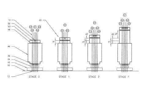
A jacking device 40 or other tensioning apparatus is used to tension the
strands
of the respective groups within the tendon assembly. As shown in Fig. 2, the
jacking
device is in the form of a sing jack and receives each of the strands of a
tendon, and
comprises an anchorage bearing plate 42 seated on bed of mortar on the dam
spillway
as generally indicated by the numeral 32. A primary multi-strand anchoring
head 44 is
arranged on the bearing plate 42, which includes a plurality of clamping
wedges 36 for
preventing retraction of the tendon strands into the bore. A hydraulic
stressing/tensioning jack 46 is seated on the anchoring head 44.
Alternatively, an
intermediate chair or frame can be used. In turn, an auxiliary anchoring head
48 is
disposed on the jack 46 and is provided with seating apertures 50 respectively
receiving
a different strand 12 of the tendon. To grip and tension respective of the
strands,
clamping wedges 52 are selectively inserted into the corresponding seating
aperture 50
of the auxiliary anchoring head about the selected strand, and the jack 46 is
operated.
For example, to tension a 91 strand anchoring tendon, a 2200 tonne capacity
hydraulic
jack is used whilst, for example, 1500 tonne and 650 tonne capacity hydraulic
jacks can
be respectively used for 65 strand and 27 strand anchoring tendons.
In accordance with the invention, different groups of the strands 12 are
tensioned in a predetermined sequence by the jack 46 to extend each of the
groups to a
respective initial displacement length to provide load transfer to the rock
foundation 30.
The respective groups of the stands 12 are then collectively tensioned at the
same time
by the jack 46 and extended to their final displacement length. Typically, the
initial
tensioning of each group of strands is such that the individual strands in all
the groups
are substantially equally stressed regardless of the free length of the
strands in each
group. That is, the different groups of the strands are respectively tensioned
in the
predetermined sequence to achieve substantially the same level of
stress/tension in all
of the strands of the tendon, and then the strands are collectively tensioned
at the same
time to the final anchor load specified for the tendon. The different groups
of the
strands can be differentially identified (and thereby be notionally ordered)
to indicate
the sequence in which the groups are to be tensioned by any suitable method,
such as
being marked, cut to different lengths, tagged or colour coded (e.g., by paint
or heat
shrink wrap). Normally, the strands are divided into different groups on the
basis of
WO 2012/024725 CA 02809429 2013-02-22PCT/AU2011/001082
12.
their respective free lengths, and the groups are tensioned in sequence from
strands with
the longest free length(s) 14 to those with the shortest free length(s).
The tensioning of the strands 12 of respective of the anchoring tendons 10 in
the
dam spillway 26 is also illustrated in Fig. 2. Whilst a tendon 10 is shown
with only 5
strands 12 divided into 3 groups (G1-G3), it will be understood that the
illustrated
tensioning method is applicable to tendons with any number of strands (e.g.,
91
strands).
As an initial step, the length that each group of strands of the tendon is to
be
extended to compensate for the difference in free lengths of the strands is
calculated.
The group with the longest free length is engaged first, and the strands in
that group are
extended by a distance that is equivalent to the difference in the required
extension
length between that group and the group of strands having the second longest
free
length. Both of those groups are then extended a distance that is equivalent
to the
difference in the required extension between the second of the groups and the
group of
strands having the longest free length. For tendons with more than three
groups of
strands, this process is repeated for each consecutive strand group. That is,
the first
three groups of strands are then extended by the difference in the required
extension
length between the third group of strands and the group of strands having the
next
longest free length, and so on. Once the second last group has been extended
to its
initial displacement length, all of the groups are then collectively extended
by the same
distance and at the same time to their respective final displacement lengths
to provide
the required tension in the strands of the tendon for load transfer to the
underlying rock
anchorage 30. At this point, all of the strands of the tendon are generally
under
substantially the same stress and loading. Thus, as will be understood, the
overall
length that each group of strands of the tendon is extended is dependent on
the different
free lengths of the respective groups of the strands, the requisite level of
load transfer
for the particular application in which the tendon is employed, and the
material
properties of the respective groups of strands.
More specifically, as illustrated in Fig. 2, the group 1 strand(s) (G1) (i.e.,
with
the longest free length(s)) are initially tensioned by seating wedges 52 in
the auxiliary
anchoring head 48 about respective of the strands and operating the hydraulic
jack 46 to
extend the strands in that group a distance dl. The group 2 strands (G2) are
then
CA 02809429 2013-02-22
WO 2012/024725 PCT/AU2011/001082
13.
gripped, and the G1 and G2 group strands are tensioned with the use of further
wedges
52 by operating the jack to extend the G1 and G2 strands a distance d2. This
cycle is
repeated as needed until all groups of strands except the last strand group of
the tendon
have been sequentially tensioned to their respective initial displacement
length. Once,
the initial tensioning of the strands in all but the last strand group has
been achieved, the
last strand group (in this case G3) is then engaged and the jack 46 is then
operated to
collectively extend all of strands of the respective groups at the same time a
further
final distance df to their final tension and respective final displacement
length as
generally illustrated in Stage F of Fig. 2. Thus, the tensioning of respective
of the
groups of strands in the predetermined sequence to their initial displacement
length in
the exemplified embodiment comprises progressively collectively tensioning
groups
lower in the order with each group that is higher in the order, in turn. As
also shown in
Fig. 2, in the present embodiment, the groups of the strands are sequentially
tensioned
in a direction radially outwardly from the centre group(s) of the strands
(e.g., radially
outwardly from the G1 strands).
The process illustrated in Fig. 2 assumes that the level of slack in the free
length
of the strands 12 in the respective groups of the tendon 10 is equal between
the groups,
and that correction for this slack occurs evenly across all of the strand
groups during the
tensioning of the strand groups. However, the differences in the slack in free
strand
length between different groups of strands compared to the shortest group of
strands
can be individually compensated for during the extension of the respective
strand
groups of the tendon to their initial displacement length in a method embodied
by the
invention. This can include tensioning each group of strands to a
predetermined initial
tension level (e.g., say 5% of the determined final tension in the strands) to
provide for
"zero correction".
In particular, in Fig. 5 and Fig. 6, a tendon 10 as described in Fig. 1 is
illustrated
with groups of strands Gl, G2 and G3 although, the respective sleeves 16 are
not
shown. As with the embodiment shown in Fig. 1, strand group G1 has the longest
free
length, group G2 has a shorter free length, and group G3 the shortest free
length.
Assuming the final stressing tension is equally distributed across all strands
12 of the
tendon in the anchored load, the extended final length of respective of the
strands is
proportional to their respective free length and the specific physical
characteristics of
WO 2012/024725 CA 02809429 2013-02-22PCT/AU2011/001082
14.
the individual strands of each strand group. Hence, a strand 12 with a longer
free length
has a longer extension length than a strand 12 with a shorter free length in
the anchored
load. Thus, in the tendons 10 shown in Fig. 5 and Fig. 6 (as well as Fig. 1),
the final
extension length in the anchored load for strand group G1 is El, the final
extension
length for strand group G2 is E2, and the final extension for strand group G3
is E3,
where for the free lengths (fl), fl(G3) < fl(G2) < fl(G1) and final extension
lengths of
the strand groups are E3 <E2 < El . The differences between these pre-
calculated
extension lengths allows compensation for slack in the free length of the
strands in the
respective strand groups to be provided in the tensioning process as further
described
below.
The method illustrated in Fig 5 assumes the initial slack in the free length
of the
respective strand groups of the tendon 10 is essentially insignificant. Stage
10 shows
the starting condition prior to commencement of the tensioning the tendon,
where all
strands of the tension are unloaded. In Stage 11, strand group G1 is initially
extended a
distance dll by the jack to its initial displacement length where dll = El -
E3. That is,
each strand in group G1 is extended by dll to eliminate the difference in free
length
between this group and the shortest free length group G3. Similarly in Stage
12, the
strands in group G2 are extended by a distance d12 where d12 = E2 - E3.
However, in
this embodiment, strand group G1 is not further extended with the initial
extension of
group G2 as occurs in the embodiment illustrated in Fig. 2. Moreover, only 2
of the 3
stand groups (G1-G3) are initially extended to remove the length difference
between the
groups. After completion of Stage 12, the final Stage FF involving the
collective
tensioning of all of strand groups Gl-G3 simultaneously by a distance dFF to
the final
extension length of the respective strand groups is undertaken. That is,
distance dFF is
equal to the extension of the shortest free length strand group (G3) from zero
to the
final extension length for group G3. The total extension length therefore
varies for each
strand group, and is based on the difference of the free strand length between
each
strand group calculated utilising values El, E2 and E3.
A method of tensioning the tendon 10 which more accurately accounts for slack
in the different strand groups is illustrated in Fig. 6. In this embodiment, a
common
preliminary tension level is introduced into each respective strand group
before the
group is extended to its initial displacement length. The introduction of the
common
WO 2012/024725 CA 02809429 2013-02-22PCT/AU2011/001082
15.
preliminary tension in the strand groups removes the slack in the free length
of the
strands in each group and provides a pre-set starting point for the subsequent
tensioning
of the strand groups.
The necessary displacement of the respective strand groups of the tendon 10 to
achieve the required anchoring of a load via the method illustrated in Fig. 6
can be
determined as follows. Firstly, the displacement lengths El, E2 and E3
required to
extend the respective strand groups from their starting length to the final
tension is
calculated, and a common preliminary tension (i.e., stressing force) "fX" is
adopted for
each strand group. As described above, the value of fX may be say 5% of the
final
calculated stressing force to which the tendon is to be tensioned to anchor
the load,
although lower or higher fX values can be employed as may be deemed
appropriate for
the particular situation.
The total displacement lengths El, E2 and E3 required to extend the respective
strand groups from their starting length to their final tension is then
calculated. The
displacement length required to extend the respective strand groups from when
the
common tension fX is applied to the strand groups (providing a "zero load"
starting
point) to their respective final displacement lengths is also determined as
EX1 for group
Gl, EX2 for group G2 and EX3 for group G3. The staged tensioning sequence of
the
tendon 10 in the method of Fig. 6 is then:
= Stage 20 in which the strands of the different strand groups are all at
their starting length prior to the commencement of tensioning of the
tendon;
= Stage 21 in which group G1 is extended to apply the preliminary tension
fX to respective of the strands in that group, and the group is then
extended by displacement d21 wherein d21 = (El -EX1)+(EX3-E3);
= Stage 22 in which group G2 is extended to apply the preliminary tension
fX to respective of the strands in that group, and the group is then
extended by a displacement of d22 wherein d22 = (E2-EX2)+(EX3-E3);
= Stage 23 in which G3 is extended to apply only the preliminary tension
fX to respective of the strands in that group; and
CA 02809429 2013-02-22
WO 2012/024725 PCT/AU2011/001082
16.
= Stage FFF in which all groups are simultaneously extended by a distance
dFF by the jack to their final displacement length wherein
dFFF = E3-EX3
Compared to the method of Fig. 5, in the embodiment of Fig. 6 the tendon group
with the shortest free length (e.g., G3) is also tensioned to the preliminary
tension level
thereby adding an addition step in the tensioning process. Moreover, whilst in
the
embodiment of Fig. 6 the common preliminary tension is applied to a strand
group and
that strand group is then extended to its respective initial displacement
length prior to
this being repeated for the next strand group in the tensioning sequence, in
other
embodiments all of the strand groups may first be tensioned in sequence to the
preliminary tension level and subsequently then be tensioned to their
respective initial
displacement lengths, generally in the same sequence.
In tendons grouted over their full length the tensioning method illustrated in
Fig. 2 or Fig. 5 are the most appropriate to use as any free length slack
prior to
tensioning of the tendon will generally not be significant to the final
result.
From the description of the above embodiments of the invention, it can be seen
that individual groups of the strands are initially extended by a different
length
compared to one another so as to be tensioned to a respective initial
displacement length
from a resting condition in the bore and to a greater tension level than a
final group of
the strands, prior to subsequent tensioning of all of the groups of the
strands at the same
time by the same predetermined length to a respective final displacement
length.
The displacement length that the different groups of strands 12 are
respectively
extended in the tensioning stages of methods embodied by the invention to
tension the
tendon 10 can be readily calculated by a civil engineer or qualified
technician prior to
effecting the tensioning, and is a function of the relative strand free length
and relative
bond length location of the respective strand group (i.e., G1-G3 etc.) as well
as the
overall length of, and load required in, the tendon. Typically, the strands of
a tendon 10
will be divided into 2 to 5 strand groups and the groups then tensioned in
sequence to
their respective initial displacement length as described above, before all of
the strand
group are collectively tensioned at the same time with a single jacking device
to their
respective final displacement length and thereby tension.
WO 2012/024725 CA 02809429 2013-02-22PCT/AU2011/001082
17.
Typically, all of the strands within a strand group will be tensioned at the
same
time during the tensioning of the group. However, in at least some
embodiments, the
strands within a strand group can be respectively individually tensioned
utilising a
suitable strand jacking arrangement during a preliminary and/or intermediate
tensioning
stage although, all of the strand groups in such embodiments are nevertheless
still
tensioned simultaneously to their respective final displacement length in the
final
tensioning stage.
The bond lengths of the strands of the tendon 10 are staggered along the bond
zone of the tendon and define respective load transfer regions for transfer of
load from
the tendon to the rock foundation, via the grout about the bond lengths of the
strands
within the corrugated sheath 24 and the grout in the bore about that sheath.
The
corrugations of the sheath 24 facilitate the mechanical load transfer through
the sheath
via the internal and external grouts.
Upon the strands 12 of the tendon 10 being stressed/tensioned to the final
required tension, the hydraulic jack and the auxiliary anchorage are removed,
and the
protruding strands 12 projecting from the primary anchoring head 44 are cut
evenly to a
manageable length. The clamping wedges 36 remain permanently in position in
the
primary anchoring head 44 to maintain the tension in respective strands of the
tendon
and secure the tendon via the bearing plate 42 to the dam spillway (i.e., the
load). The
protruding strand ends 12 can be treated (e.g., greased) to inhibit corrosion
before
encasement and/or a cover is fitted over the strands and fastened in position
with the
use of mechanical fasteners such as screws or bolts.
A tendon used in an embodiment of the invention can have any number of
strands, limited only by geotechnical, grout and project's physical
restrictions.
Typically, when tensioned to their final tension, the tension in the
respective strands of
the tendon can be within 2-3% of MBL (Minimum Breaking Load) relative to each
other. This difference in tension is an effect of necessary stagger in the
position of the
free length/bond length junction of the strands, where it is not possible to
abruptly have
all strands within a group coincide at exactly the same location, due to
spacial
constraints and possible differing properties of different batches of strand
that may be
utilised within the one tendon.
WO 2012/024725 CA 02809429 2013-02-22PCT/AU2011/001082
18.
From the above, it will be clear that embodiments of the invention provide for
the use of anchoring tendons in situations with relatively low geotechnical
strength
materials through to tendons as exemplified above (e.g., 91 strand) to provide
for ultra-
high load transfer capacity tendons with greater than 91 strands, e.g.,
>25,400 kN UTS.
More particularly, the load transfer capacity of a tendon tensioned in
accordance with
an embodiment of the invention will typically be at least about 1500 kN UTS,
and more
preferably, at least about 3000 kN UTS, 5000 kN UTS, 7000 kN UTS, 8000 kN UTS,
13750 kN UTS or 16250kN UTS or greater. Moreover, while the invention has been
described herein in relation to the use of ground tendons with multiple, multi-
wire
strands 12, it will be understood the invention extends to tendons with
multiple rod or
bar strands or the like.
Although the invention has been described in relation to a number of
embodiments, it will be appreciated that numerous variations and modifications
can be
made without departing from the invention. The present embodiments are,
therefore,
merely illustrative and not restrictive.