Note: Descriptions are shown in the official language in which they were submitted.
81632169
1
SIDE RAIL OF A FLATBED TRAILER
FOR USE WITH CARGO RESTRAINT DEVICES
[0001]
Field Of The Invention:
[0002] The present invention relates generally to a side rail of a floor
assembly
for a transportation vehicle, such as a flatbed trailer, for example. In
particular, the
present invention relates to a side rail of a flatbed trailer configured to
accommodate
two different cargo restraint cargo restraint devices to allow a user to use
one or both
devices to restrain or position cargo on the floor assembly.
BACKGROUND OF THE INVENTION
[0003] When transporting bulky loads, such as cargo, from place to place
on a
trailer, such as a flatbed trailer, for example, the load is typically secured
to the trailer in
order to prevent the load from moving relative thereto. Various cargo
restraint devices
are provided for securing the cargo to the trailer and the trailer may be
configured in one
or more ways to allow a particular type of cargo restraint device to be
coupled thereto.
An example of one such device is a chain tie-down device such as that
described in
U.S. Patent No. 7,537,423. A flatbed trailer may be configured such that a
chain tie-
down device is able to be provided in a side rail of the floor assembly of a
flatbed trailer,
for example. Another cargo restraint device includes a multi-position sliding
bracket
configured to slide along a channel typically located in the side rail of the
floor assembly
of the trailer. The sliding bracket is able to be positioned at any location
within the
channel and along the length of the trailer side rail in order to provide an
optimal
location for securing cargo on the trailer. Typically, the side rail of the
trailer may be
configured to accept either the chain tie-down restraint device or the sliding
bracket (i.e.,
CA 2809530 2019-02-15
CA 02809530 2013-03-14
WNC-2012-05
2
multi-position) restraint device, but not both, thus limiting the means
available to the
user to tie down or restrain various cargo loads on the trailer.
SUMMARY
[0004] The present invention may comprise one or more of the features
recited in
the attached claims, and/or one or more of the following features and
combinations
thereof.
[0005] According to one aspect of the present disclosure, a side rail
configured to
be coupled to a cross-member of a floor assembly of a trailer, such as a
flatbed trailer,
includes a channel formed in a top wall of the side rail. The channel extends
along a
length of the side rail and is configured to receive a first cargo restraint
device therein.
The side rail further includes an aperture formed in the top wall at a
location spaced-
apart from the channel. The aperture is configured to receive a second cargo
restraint
device therein.
[0006] In one illustrative embodiment, the first cargo restraint device may
be
different from the second cargo restraint device.
[0007] In another illustrative embodiment, the aperture may be spaced
inwardly
from the channel.
[0008] In still another illustrative embodiment, the channel may be
generally J-
shaped when viewed in cross-section.
[0009] In yet another illustrative embodiment, the side rail may also
include (i) an
outer, vertical wall coupled to the top wall, and (ii) a bottom wall coupled
to the outer,
vertical wall. Illustratively, the side rail may be devoid of any angled cross
brace
extending from the top wall to either the outer, vertical wall or the bottom
wall. Further
illustratively, the outer, vertical wall may be a first outer, vertical wall,
and the side rail
may also include a second outer, vertical wall parallel to the first outer,
vertical wall.
Illustratively, the channel may be positioned generally directly above the
first and
second outer, vertical walls.
[0010] In still another illustrative embodiment, the channel formed in the
top wall
may be defined by spaced-apart vertical members and a base member coupled to
the
CA 02809530 2013-03-14
WNC-2012-05
3
bottom of the vertical members. Illustratively, a portion of the base member
may be
configured to be welded to a cross-member of the floor assembly.
[0011] In yet another illustrative embodiment, the channel may be
configured to
be positioned outside a lateral end of a cross-member of the floor assembly
when the
side rail is coupled to the cross-member.
[0012] In still another illustrative embodiment, the channel may be
positioned
outwardly from a center of the top wall when viewed in cross-section.
[0013] In another illustrative embodiment, the top wall may include a
channel
mount configured to define the channel therein. The top wall may also include
a
horizontal member and first and second vertical members extending downwardly
from
the horizontal member. Illustratively, the first and second vertical members
may be
configured to be welded to the cross-member of the floor assembly. Further
illustratively, the aperture may be positioned between the channel mount and
the
second vertical member.
[0014] According to another aspect of the present disclosure, a side rail
configured to be coupled to a cross-member of a floor assembly of a trailer,
such as a
flatbed trailer, includes a top wall having a channel mount defining a channel
extending
along a length of the side rail. The channel is configured to receive a first
cargo
restraint device therein. The top wall also includes a horizontal member
configured to
be spaced-apart from a top surface of the cross-member. The top wall further
includes
a vertical member extending downwardly from the horizontal member. The
vertical
member is configured to be coupled to the top surface of the cross-member.
Illustratively, an aperture of the side rail is formed in the horizontal
member and is
positioned between the channel mount and the vertical member. The aperture is
configured to receive a second cargo restraint device therein that is
different from the
first cargo restraint device. The side rail further includes an outer,
vertical wall coupled
to and extending downwardly from the channel mount. The outer, vertical wall
is
configured to engage an outer end of the cross-member.
[0015] In one illustrative embodiment, the channel may be generally J-
shaped in
cross-section.
CA 02809530 2013-03-14
WNC-2012-05
4
[0016] In another illustrative embodiment, the side rail also includes
another
outer, vertical wall member coupled to and extending downwardly from the
channel
mount. Illustratively, the outer, vertical wall members are spaced-apart from
each other.
[0017] According to yet another aspect of the present disclosure, a floor
assembly of a vehicle, such as a flatbed trailer, for example, includes a
plurality of
transversely-extending cross members, a plurality of longitudinally-extending
floor
planks positioned above and coupled to a top surface of the plurality of cross
members,
and a support member configured to extend generally along a length of the
floor
assembly. Illustratively, the support member includes a top wall generally
flush with the
plurality of longitudinally-extending floor planks, and a vertical wall
coupled to the top
wall and extending downwardly therefrom such that a bottom end of the vertical
wall is
positioned generally below the cross members. Further illustratively, the
support
member is positioned between two of the longitudinally-extending floor planks.
The top
wall of the support member includes a channel formed therein which extends
along a
length of the support member. The channel is configured to receive a cargo
restraint
device therein.
[0018] In one illustrative embodiment, the channel may be generally J-
shaped
when viewed in cross-section.
[0019] In another illustrative embodiment, the channel formed in the top
wall may
be defined by spaced-apart vertical members and a base member coupled to the
bottom of the vertical members. Illustratively, the base member may be wider
than a
widest portion of the channel. Further illustratively, the base member may be
welded to
a cross-member of the floor assembly.
[0020] In yet another illustrative embodiment, the floor assembly may also
include a side rail spaced apart from the support member. The side rail may
include a
top wall defining a channel and an aperture spaced-apart from the channel.
Illustratively, the channel of the side rail may be configured to receive the
cargo restraint
device therein. Further illustratively, the aperture may be configured to
receive a
different cargo-restraint device therein.
816325169
4a
[0020a] According to one aspect of the present invention, there is provided
a side
rail of a flatbed trailer configured to (i) extend along a length of the
trailer along one side
of the trailer, and (ii) be coupled to and positioned outwardly from a
transversely-
extending cross-member of a floor assembly of the trailer, the side rail
comprising: a
channel formed in a top wall of the side rail, wherein the channel extends
along a length
of the side rail, wherein the channel is configured to receive a first cargo
restraint device
therein, and wherein the channel is configured to be positioned outside a
lateral end of
the transversely-extending cross-member of the floor assembly when the side
rail is
coupled to the cross-member; and an aperture formed in the top wall of the
side rail at a
location spaced-apart from the channel, wherein the aperture is configured to
receive a
second cargo restraint device therein, and wherein the channel is generally J-
shaped
when viewed in cross-section.
(0020b] According to another aspect of the present invention, there is
provided a
side rail of a flatbed trailer configured to (i) extend along a length of the
trailer along one
side of the trailer, and (ii) be coupled to and positioned outwardly from a
cross-member
of a floor assembly of the trailer, the side rail comprising: a top wall; and
a vertical wall
coupled to an outer end of the top wall to extend downwardly below a bottom-
most
surface of the top wall in order to define a generally L-shaped side rail when
viewed in
cross-section, wherein the vertical wall is configured to be positioned
outside of and
engaged with an outer end of the cross-member of the floor assembly of the
trailer,
wherein the top wall includes a generally J-shaped channel configured to
extend along
a length of the side wall in order to receive a first cargo restraint device
therein, wherein
the channel is positioned at the outer end of the top wall, and wherein the
channel is
positioned directly above the vertical wall, and wherein the top wall includes
a horizontal
member, an aperture through the horizontal member and positioned at a location
spaced inwardly from the channel, and first and second vertical members
extending
downwardly from the horizontal member and configured to be welded to a top
surface of
the cross-member, wherein the aperture is positioned between the first and
second
vertical members.
[0020c] According to still another aspect of the present invention, there
is provided
a floor assembly of a vehicle, comprising: a plurality of transversely-
extending cross
CA 2809530 2019-10-11
816325169
4b
members; a plurality of longitudinally-extending floor planks positioned above
and
coupled to a top surface of the plurality of cross members; and a support
member
configured to extend generally along a length of the floor assembly, the
support member
including a top wall generally flush with the plurality of longitudinally-
extending floor
planks, and a vertical wall coupled to the top wall and extending downwardly
therefrom
such that a bottom end of the vertical wall is positioned generally below the
cross
members, wherein the support member is positioned between two of the
longitudinally-
extending floor planks, and wherein the top wall of the support member
includes a
channel formed therein which extends along a length of the support member, the
channel being configured to receive a cargo restraint device therein; wherein
the
channel formed in the top wall is defined by spaced-apart vertical members and
a base
member coupled to the bottom of the vertical members, wherein the base member
is
wider than a widest portion of the channel; and wherein one of the vertical
members
defines a width greater than another one of the vertical members.
[0020d]
According to yet another aspect of the present invention, there is provided
a floor assembly of a vehicle comprising: a plurality of transversely-
extending cross-
members; a plurality of longitudinally-extending floor planks positioned above
and
coupled to a top surface of the plurality of cross-members; a pair of spaced-
apart
support members extending along a length of the floor assembly and positioned
laterally
inward of outer sides of the floor assembly; and a cross-brace coupled to and
extending
between the pair of support members, wherein each support member includes (i)
a top
wall positioned above and coupled to a top surface of the plurality of cross-
members
and (ii) a vertical wall coupled to the top wall and extending downwardly
therefrom such
that a bottom end of the vertical wall is positioned generally below the cross
members,
wherein the top wall of each support member defines a channel which extends
along a
length of the support member and is configured to receive a first cargo
restraint device
therein, and wherein each channel is defined by spaced-apart vertical members
of the
respective top wall and a base member of the respective top wall coupled to
the bottom
of the vertical members and couple to the top surface of the cross members,
wherein
the base member is wider than a widest portion of the channel; and wherein one
of the
CA 2809530 2019-10-11
816325169
4c
vertical members of the top wall of each support member defines a width
greater than
another one of the vertical members of said top wall.
[0020e] According to a further aspect of the present invention, there is
provided a
floor assembly of a vehicle comprising: a plurality of transversely-extending
cross-
members; a plurality of longitudinally-extending floor planks positioned above
and
coupled to a top surface of the plurality of cross-members; a pair of spaced-
apart
support members extending along a length of the floor assembly and positioned
laterally
inward of outer sides of the floor assembly; and a cross-brace coupled to and
extending
between the pair of support members, wherein each support member includes (i)
a top
wall positioned above and coupled to a top surface of the plurality of cross-
members
and (ii) a vertical wall coupled to the top wall and extending downwardly
therefrom such
that a bottom end of the vertical wall is positioned generally below the cross
members,
wherein the top wall of each support member defines a channel which extends
along a
length of the support member and is configured to receive a first cargo
restraint device
therein, further comprising a side rail extending along a length of one side
of the vehicle,
the side rail being coupled to and positioned outwardly from the transversely-
extending
cross members, wherein the side rail includes a top wall defining a side rail
channel
extending along a length of the side rail and configured to receive the first
cargo
restraint device therein, and wherein the side rail includes an outer,
vertical wall coupled
to an outer end of the top wall of the side rail and depending downwardly
below the
cross-members, and wherein the side rail includes an aperture formed in the
top wall of
the side rail at a location spaced-apart from the side rail channel, and
wherein the
aperture is configured to receive a second cargo restraint device therein.
[0020f] According to yet a further aspect of the present invention, there
is
provided a floor assembly of a vehicle comprising: a plurality of transversely-
extending
cross-members; a plurality of longitudinally-extending floor planks positioned
above and
coupled to a top surface of the plurality of cross-members; and a pair of
spaced-apart
support members extending along a length of the floor assembly and positioned
laterally
inward of outer sides of the floor assembly, wherein each support member
includes (i) a
top wall positioned above the plurality of cross-members and (ii) a vertical
wall coupled
to the top wall and extending downwardly therefrom such that a bottom end of
the
CA 2809530 2019-10-11
816325169
4d
vertical wall is positioned generally below the cross members, and wherein the
top wall
of each support member defines a channel which extends along a length of the
support
member and is configured to receive a first cargo restraint device therein,
and wherein
the channel formed in the top wall is defined by spaced-apart vertical members
and a
base member coupled to the bottom of the vertical members, wherein the base
member
is wider than a widest portion of the channel; and wherein one of the vertical
members
defines a width greater than another one of the vertical members.
[0020g] According to another aspect of the present invention, there is
provided a
floor assembly of a vehicle comprising: a plurality of transversely-extending
cross-
members; a plurality of longitudinally-extending floor planks positioned above
and
coupled to a top surface of the plurality of cross-members; and a pair of
spaced-apart
support members extending along a length of the floor assembly and positioned
laterally
inward of outer sides of the floor assembly, wherein each support member
includes (i) a
top wall positioned above the plurality of cross-members and (ii) a vertical
wall coupled
to the top wall and extending downwardly therefrom such that a bottom end of
the
vertical wall is positioned generally below the cross members, and wherein the
top wall
of each support member defines a channel which extends along a length of the
support
member and is configured to receive a first cargo restraint device therein,
and wherein
the channel is generally J-shaped when viewed in cross-section.
BRIEF DESCRIPTION OF THE DRAWINGS
[0020h] FIG. 1 is a rear end view of a flatbed trailer of the present
disclosure
showing a floor assembly of the trailer including right and left side rails
each configured
for use with two different cargo restraint systems, and further showing two l-
beams of
the floor assembly configured for use with one of the cargo restraint systems.
[0020i] FIG. 2 is a sectional view through the right side rail of the
trailer of FIG. 1
(as viewed from the rear end of the trailer) showing first and second
restraint systems
coupled to the side rail of the trailer for securing cargo thereon.
[0020j] FIG. 3 is a perspective view of a portion of the flatbed trailer of
FIGS. 1
and 2 showing the first and second restraint systems coupled to the side rail
of the
trailer.
CA 2809530 2019-12-20
816325169
4e
[0020k] FIG. 4 is an end view of a portion of the flatbed trailer of FIGS.
1-3
showing an upper member of one of the longitudinally-extending I-beams of the
floor
assembly and further showing one of the cargo restraint systems coupled
thereto.
[00201] FIG. 5 is a perspective view of a portion of an alternative side
rail for use
with the first and second restraint systems.
[0020m] FIG. 6 is a sectional view similar to FIG. 2 showing a floor
assembly
including of the side rail of FIG. 5 and showing first and second restraint
systems
coupled to the side rail of the trailer for securing cargo thereon.
CA 2809530 2019-12-20
CA 02809530 2013-03-14
WNC-2012-05
DETAILED DESCRIPTION OF THE PREFERRED EMBODIMENT
[0021] For the purposes of promoting an understanding of the principles of
the
invention, reference will now be made to illustrative embodiments shown in the
attached.
drawings and specific language will be used to describe the same. While the
concepts
of this disclosure are described in relation to a flatbed trailer, it will be
understood that
they are equally applicable to other vehicles generally, and more specifically
to
conventional truck and/or box or van type trailers (dry van and refrigerated),
examples
of which include, but should not be limited to, straight truck bodies, small
personal
and/or commercial trailers and the like. Accordingly, those skilled in the art
will
appreciate that the present invention may be implemented in a number of
different
applications and embodiments and is not specifically limited in its
application to the
particular embodiments depicted herein.
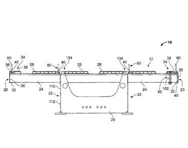
[0022] Looking first to FIGS. 1-3, a flatbed trailer 10 includes a floor
assembly 12,
a rear wheel assembly (not shown), and a kingpin (not shown) configured to be
coupled
to a tractor (not shown) for towing the flatbed trailer 10. The floor assembly
12 of the
flatbed trailer 10 includes first and second side rails 20 each configured to
extend along
a length of the trailer 10 along the right and left sides of the trailer 10,
as shown in FIGS.
1 and 2, for example. The floor assembly 12 further includes longitudinally-
extending
support beams, such as the I-beams 22 shown in FIG. 1, for example, as well as
transversely-extending cross-beams 24 also shown in FIGS. 1 and 3. A cross-
brace 26
is coupled to and extends between the I-beams 22. Floor planks 28 of the floor
assembly 12 extend longitudinally along the trailer 10 and rest on the cross
beams 24,
as shown best in FIGS. 1 and 4.
[0023] As noted above, the floor assembly 12 includes first and second side
rails
20 such that each side rail 20 extends along a length of the right and left
sides of the
trailer 10. In particular, one side rail extends along one side of the floor
assembly 12
while the other side rail 20 extends along the other side of the floor
assembly 12. For
purposes of the description herein, however, only one side rail 20 will be
described
herein. However, it should be understood that the two side rails 20 of the
trailer 10 are
identical in configuration and function.
CA 02809530 2013-03-14
WNC-2012-05
6
[0024] Illustratively, as shown in FIG. 2, the side rail 20 includes an
outer, vertical
wall 30, a bottom, inwardly-extending wall 32 coupled to a bottom end of the
vertical
wall 30, and a top, inwardly-extending wall 34 coupled to a top end of the
vertical wall
30. The top wall 34 includes an outer top wall member 36 and an inner top wall
member 38 spaced-apart from the outer top wall member 36 by a longitudinally-
extending groove, or channel, 40 formed in the top wall 34 of the side rail
20.
Illustratively, the channel is defined by a channel mount 43 of the top wall
34. In
particular, the channel mount 43 includes a first vertical member 42 coupled
to the outer
top wall member 36, a second vertical member 44 coupled to the inner top wall
member
38 and spaced-apart from the first vertical member 42, and a base wall member
46
coupled to a bottom end of each of the first and second vertical members 42,
44 to
define the channel 40 therebetween. As shown in FIG. 2, the base wall member
46
includes a horizontal member 49 and an upwardly-extending lip 51 coupled to an
inward
end of the horizontal member 49. Illustratively, as viewed from an end view of
the trailer
10, the horizontal member 49 of the base wall 46 extends transversely to the
right and
left beyond the first and second vertical members 42, 44 such that a width 50
of the
base wall member 46 is greater than a width 52 of a widest portion of the
channel 40
and is also greater than a distance between the outer surfaces of the vertical
walls 42,
44 which define the channel 40. Illustratively, the width 50 is approximately
2.5 inches
and the width 52 is approximately 1.0 inches while the distance between the
outer
surfaces of the vertical walls 42, 44 is approximately 1.6 inches. However, it
should be
understood that it is within the scope of the disclosure for the base wall
member 46 to
include any suitable dimensions as well.
[0025] Illustratively, the top wall 34 further includes a third vertical
member 54
spaced inwardly from the second vertical member 44 and extending downwardly
from
an innermost end of the top wall member 38. A transversely-extending flange 56
of the
top wall 34 is coupled to the bottom end of the inner, vertical member 54, as
shown in
FIG. 2. Further, illustratively, the side rail 20 specifically does not
include a generally
diagonally-extending cross member extending between the top wall 34 and either
the
vertical, outer wall 30 or the bottom wall 32. As is discussed in greater
detail below, the
CA 02809530 2013-03-14
WNC-2012-05
7
horizontal wall member 49 of the base wall 46 is configured to be welded to
the cross
members 24 of the floor assembly 12 in order to provide additional strength to
the side
rail 10 while the lack of any cross member of the side rail 20 aides in
providing sufficient
room for the use of first and second cargo restraint devices with the side
rail 20.
[0026] Illustratively, the channel 40 defined in the top wall 34 of the
side rail 20 is
generally J-shaped in cross-section such that a top opening 60 of the channel
40
defines a width that is smaller than the width 52 of the bottom-most portion
of the
channel 40. The top opening 60 is thus defined by a lip 62 of the top wall
member 38
which extends outwardly from the second vertical wall member 46, as shown in
FIG. 1.
[0027] As shown in FIGS. 1 and 2, the side rail 20 is configured to be
coupled to
the cross beams 24 of the floor assembly 12 such that the bottom wall 32 is
positioned
below the cross beams 24 and the top wall 34 is positioned above and in
engagement
with a top surface 64 of the cross beams 24. As shown in FIG. 2, the top wall
members
36, 38 of the top wall 34 are spaced-apart from the top surface 64 of the
cross members
24. Illustratively, the side rail 20 is located at the outermost sides of the
floor assembly
12 of the trailer 10 and is coupled to the outer ends of the cross members 24
of the floor
assembly 12. In particular, a bottom surface of the horizontal member 49 of
the base
wall 46 and a bottom surface of the flange 56 are engaged with the top surface
64 of the
cross beams 24. Illustratively, therefore, the flange 56 and the horizontal
member 49 of
the base wall 46 are welded to the top surface 64 of the cross members 24 in
order to
secure the side rail 20 thereto. It should be understood that while the side
rail 20 is
welded to the cross members 24, it is also within the scope of this disclosure
for the
side rail 20 to be coupled to the cross members 24 using any suitable
mechanical
fastener and/or adhesive including, but not limited to, rivets, nails, screws,
nuts and
bolts, epoxies, etc. Illustratively, the side rail 20 is made from an extruded
piece of
aluminum. However, it should be understood that the side rail 20 may be made
from
one or more any suitable materials including, but not limited to metals, metal
alloys,
plastics, composites, and wood, for example. Further, it is within the scope
of the
disclosure to provide a side rail that is not extruded as a single component,
but is made
of separate components coupled together.
CA 02809530 2013-03-14
WNC-2012-05
8
[0028] Illustratively, as shown in FIG. 2, a width 70 of the outer top wall
member
36 is less than a width 72 of the inner top wall member 38 such that the
channel 40
formed in the top wall 34 is positioned outwardly from a vertical centerline
74 shown in
FIG. 1 through a center of an overall width 76 of the top wall 34.
Specifically, the width
70 of the outer top wall member 36 is approximately 0.88 inches while the
width 72 of
the inner top wall member 38 is approximately 4.43 inches and the overall
width 76 of
the top wall 34 is approximately 6.74 inches.
[0029] A first cargo restraint device 80 is provided for use with the side
rail 20 of
trailer 10. Illustratively, the first cargo restraint device 80 is a sliding
load securement
bracket. In particular, the bracket 80 is provided for use with the channel 40
formed in
the side rail 20. Illustratively, the bracket 80 is generally rectangular (as
shown in FIG.
3) and defines a generally J-shaped cross-section (as shown in FIGS. 1 and 2).
The
bracket 80 includes an aperture 82 (as shown in FIG. 3) formed through an
upper, body
section 84 while a lower, J-section 86 is received within the channel 40 of
the side rail
20. When properly coupled to the side rail 20, a lip on the J-section 86 of
the bracket
engages the lip 62 of the side rail 20 in order to prevent the bracket 80 from
being
vertically removed from the channel 40.
[0030] In use, the bracket 80 may be moved, or slid, within the channel 40
along
a longitudinal length of the side rail 10 in order to position the bracket 80
at any suitable
location on the trailer 10 in order to properly secure cargo to the trailer
10. A securing
chain or strap (not shown) for use in either retaining or positioning cargo
may be
attached to the mounting bracket 80 by a hook, for example, placed through the
aperture 84 in order to secure or position cargo on the trailer 10. When the
hook is
placed under tension, the mounting bracket 80 is moved upwardly to draw the
lip of the
J-section 86 against the lip 62 of the top wall 34 of the side rail 20. While
the bracket 80
is only shown in a generally vertical orientation on the side rail 20, it
should be
understood that the bracket 80 is also pivotable within the channel 40 such
that the
main body 84 of the bracket 80 may be positioned at any suitable angle
relative to the
generally flat upper surface of the top wall 34 of the side rail 20. When not
in use, the
bracket 80 may be removed, or uncoupled, from the side rail by rotating the
main body
CA 02809530 2013-03-14
=
WNC-2012-05
9
84 in an inward direction to disengage the lip 62 of the side rail 20 from the
corresponding lip or J-section 86 of the bracket 80 and removing the J-section
86 of the
bracket 80 from the channel 40.
[0031] As shown in FIGS. 1-3, the side rail 20 of the trailer 10 is
configured to
accommodate a second cargo restraint device 90. Illustratively, the side rail
20 includes
an aperture 92 formed in the inner top wall member 38, through which the
second cargo
restraint device 90 may be located. In particular, the second cargo restraint
device 90 is
a chain tiedown such as that described in U.S. Patent No. 7,537,423, for
example. As
shown in FIGS. 1 and 2, the illustrative restraint device 90 generally
includes an upper
cap 100, a chain 102 extending downwardly from the cap 100, and an end lock
104
coupled to a bottom end of the chain 102. Illustratively, a diameter of the
cap 100 is
generally the same or similar size as a diameter of the aperture 92 formed in
the side
rail 20 such that a top surface of the cap 100 is generally flush with a top
surface of the
outer wall member 38 of the side rail 100 when the device 90 is installed
therein. A bar
108 is illustratively welded to an underside of the inner top wall member 38
and an
aperture 110 formed therethrough is aligned with the aperture 92 formed in the
side rail
20. The aperture 110 is smaller than the aperture 92 and smaller than the cap
100 of
the device 90 such that an outer rim of the cap 100 is configured to rest on a
portion of
the bar 108 around the aperture 110 in order to support the cap 100 thereon.
In use, a
securing chain or strap for use in either retaining or positioning cargo may
be attached
to a link of the chain 102 of the device 90 by a hook, for example, in order
to secure or
position cargo on the trailer 10. When the hook is placed under tension, the
device 90
is moved upwardly to draw the end lock 104 tightly against a bottom surface of
the bar
108.
[0032] Illustratively, as shown in FIG. 1, the aperture 90 is positioned
inwardly
(i.e., toward the center of the trailer 10 and away from the outer vertical
wall 30 of the
side rail 20) of the channel 40 formed in the top wall 34 of the side rail 20
in order to
position the second cargo restraining device, i.e. the chain tie down 90,
inwardly of the
first cargo restraining device 80, i.e. the mounting bracket 80. As shown in
FIG. 3, the
top wall 34 includes a number of apertures 92 formed therein in order to
accommodate
CA 02809530 2013-03-14
WNC-2012-05
a number of devices 90. It should be understood that the side rail 20 may be
provided
with any one or more apertures 92 formed therein in order to accommodate one
or more
devices.
[0033] Thus, the side rail 20 is configured to accommodate two different
types of
cargo restraining devices therein. In particular, the channel 40 is configured
to
cooperate with the mounting bracket 80 to provide .a multi-position, sliding
cargo
restraining device. Further, the one or more apertures 92 of the side rail 20
are
configured to cooperate with the second cargo restraint device 90 to provide a
chain tie
down restraining device. Typically, a side rail of a flatbed trailer, such as
the trailer 10,
is only able to accommodate one cargo restraining device such that a typical
trailer may
include either a channel configured to cooperate with a mounting bracket or an
aperture
configured to cooperate with a chain tie down device 90, but not both. Such
limited
accommodations are oftentimes due to constrains in the size of the top wall of
a side rail
and/or to placement of supporting cross-braces typically found in many side
rails.
Oftentimes one particular cargo restraining device may be desired over the use
of
another cargo restraining device depending upon the size, shape, and/or weight
of the
cargo to be carried on the floor assembly 12 of the trailer 10. Thus,
providing a trailer
10 capable of accommodating two different cargo restraining devices therein
provides a
use with the ability to use one or more different types of cargo restraint
devices in order
to better accommodate different types of cargo loads to be carried on the
trailer 10.
[0034] Illustratively, the wide width of the base member 46 of the side
rail 20
provides additional strength to the side rail 20 in order to help prevent the
side rail 20
from bending or otherwise deforming due to loads placed on the side rail 20
via the
mounting bracket 80 and/or the chain tie 90 when these cargo restraining
devices 80,
90 (and the corresponding restraining straps) are used to restrain cargo on
the floor
assembly 12 of the trailer 10. As noted above, the entire width 50 of the
horizontal
member 49 of the base wall 46 is welded to the cross members 24 of the floor
assembly
in order to secure the side rail 20 to the cross members 24. Welding along the
widened width 50 of the base wall 46 provides additional strength to the side
rail 20 in
CA 02809530 2013-03-14
WNC-2012-05
11
order to further help prevent the side rail 20 from deforming due to loads
placed
thereon.
[0035] Looking now to FIG. 4, the trailer 10 further includes two
longitudinally-
extending I-beams 22 of the floor assembly 12. Such I-beams are oftentimes
constructed of two generally T-shaped members (i.e., an upper T-member 110 and
a
lower T-member 112 welded together). However, it should be understood that the
I-
beams may comprise a single component rather than the upper and lower 1-
members
110, 112 coupled together. Illustratively, the l-beams 22 are located inwardly
and are
spaced-apart from each of the first and second side rails 20 of the trailer
10. As shown
in FIGS. 1 and 4, each of the I-beams 22 includes a channel 40 formed therein.
The
channel 40 is configured to accommodate one or more mounting brackets 80 in
order to
provide an inwardly-positioned cargo restraint device. While the floor
assembly 12
includes two longitudinally-extending I-beams 22, only one I-beam will be
described
herein. However, it should be understood that the two I-beams 22 of the
trailer 10 are
identical in configuration and function.
[0036] Illustratively, as shown in FIG. 4, the upper T member 110 of the I-
beam
22 includes a top wall 134 and a vertical wall 140 coupled to the top wall 134
and
extending downwardly therefrom. Illustratively, a top surface 162 of the top
wall 134 is
generally flush with a top surface 164 of the floor planks 28 while a bottom
end of the
vertical wall 140 is positioned generally below the cross members 24 of the
floor
assembly 12. The top wall 134 includes spaced-apart top wall members 136, 138,
first
and second generally vertical wall members 154 coupled to the outside end of
each of
the top wall members 136, 138, and a flange member 156 coupled to the bottom
end of
each of the vertical wall members 154. The flange members 156 are coupled to
the top
surface of the cross members 24 via welding. However, it should be understood
that
the flange members 156 of the I-beam 22 may be coupled to the cross members 24
via
other suitable fasteners including, but not limited to, rivets, nails, screws,
nuts/bolts, and
adhesives, for example. The I-beam 22 further includes a channel mount 143
defining
the channel 40 therein. The channel mount 143 of the I-beam 22 is similar to
the
channel mount 43 of the side rail 20. Illustratively, the channel mount 143
includes a
CA 02809530 2013-03-14
WNC-2012-05
12
first vertical wall 142 and a second vertical wall 144 spaced-apart from the
first vertical
wall 142. Illustratively, the second vertical wall 144 is thicker than the
first vertical wall
142. However, it should be understood that the first and second vertical walls
142 may
include any suitable thickness such that the first vertical wall may be as
thick as or
thicker than the second vertical wall 144, for example. As shown in FIG. 4 the
second
vertical wall 144 is positioned inwardly (i.e., toward a longitudinal center
of the floor
assembly 12) from the first vertical wall 142 and is coupled to a lip 62 of
the top wall
member 38 which extends outwardly (i.e., away from a longitudinal center of
the floor
assembly 12) to define the J-shape of the channel 40.
[0037] The first and second vertical walls 142, 144 are coupled to each
other by a
horizontal base wall 146 which cooperates with the first and second vertical
walls 142,
144 to define the channel 40. The channel mount 143 defines a lower, or base,
surface
145 which is configured to engage and be coupled to the upper surface 64 of
the cross
members 24 of the floor assembly 12. Illustratively, the base surface 145
defines a
width that is greater than a width of the widest portion of the channel 40. As
shown in
FIG. 4, a portion of the base surface 145 is positioned to the right (i.e.,
inward) of the
vertical wall 140 of the I-beam while another portion of the base surface 145
is
positioned to the left (i.e. outward) of the vertical wall 140.
Illustratively, the channel 40
formed within the channel mount 142 is positioned to the left of the vertical
wall 140.
[0038] The channel 40 of the I-beams 22 provides the same function as the
channel 40 formed in the side rails 20. That is, the channel 40 of each I-beam
22 is
configured to receive the mounting bracket 80 therein in order to secure cargo
on the
floor assembly 12 of the trailer 10. The mounting bracket 80 may be slid along
within
the channel 40 along the length of the top wall 134 of the I-beam 22 to be
positioned at
any suitable location. When properly coupled to the I-beam 22, a lip on the J-
section 86
of the bracket 80 engages the lip 62 of the top wall 134 of the I-beam 22 in
order to
prevent the bracket 80 from being vertically removed from the channel 40.
[0039] Looking now to FIGS. 5 and 6 an alternative side rail 220 is
provided. The
side rail 220 is similar to the side rail 20, and as such, common reference
numbers are
provided to refer to the same or similar components. Illustratively, the side
rail 220
CA 02809530 2013-03-14
=
WNC-2012-05
13
includes an outer, vertical wall 230, a bottom, inwardly-extending wall 232
coupled to a
bottom end of the vertical wall 230, and a top, inwardly-extending wall 234
coupled to a
top end portion of the vertical wall 230. The top wall 234 includes a channel
mount 243
which defines the longitudinally-extending channel 40 configured to receive
the first
cargo restraint device 80 therein. The cargo restraint device 80 is movable
within the
channel 40 in the same manner as that described above in regard to the side
rail 20.
[0040] The channel mount 243 includes an upper portion 231 of the vertical
wall
230, a vertical member 244 coupled to the top wall 234 and spaced-apart from
the
upper portion 231 of the outer vertical wall 230, and a base wall member 246
coupled to
a bottom end of the vertical member 244 and coupled to the outer vertical wall
230 to
define the channel 40 therebetween. As shown in FIG. 6, a second outer,
vertical wall
235 is coupled to the base wall member 246 of the channel mount 243 and
extends
downwardly therefrom to the bottom wall 232. Illustratively, the vertical wall
235 is
parallel to the vertical wall 230 and is spaced inwardly therefrom. As shown
in FIG. 6,
the second outer, vertical wall 235 is configured to engage an outer end of
the cross-
member 24. Further illustratively, a portion of the bottom wall 232 extends
inwardly
beyond the second outer, vertical member 235 to be positioned below and
engaged
with the cross-member 24.
[0041] Illustratively, the top wall 234 further includes a horizontal
member 236
coupled to the channel mount 243 and an additional vertical member 254
extending
downwardly from an innermost end of the horizontal member 236 of the top wall
234. A
transversely extending flange 256 of the top wall 234 is coupled to the bottom
end of the
inner, vertical member 254, as shown in FIG. 6. The top wall 234 further
includes yet
another vertical member 255 extending downwardly from the horizontal member
236 of
the top wall 234 at a location spaced outwardly from the vertical member 254.
A
transversely extending flange 257 is coupled to the bottom end of the vertical
member
255. Illustratively, the vertical member 254 and the vertical member 255 are
parallel to
each other.
[0042] Similar to the side rail 20, the side rail 220 does not include a
generally
diagonally-extending cross member or support member which extends between an
CA 02809530 2013-03-14
vik
WNC-2012-05
14
inner portion of the top wall 243 and the outer vertical wall 230.
Illustratively, the
flanges 256, 257 as well as a bottom ledge 259 of the base wall member 246 are
configured to be welded to the top surface 64 of the cross members 24 of the
floor
assembly 12. Further illustratively, both outer vertical wall members 230, 235
are
positioned outside the cross member 24 such that the second outer vertical
wall
member 235 is adjacent to and engaged with the cross member 24 while the outer
wall
member 230 is spaced-apart from the end of the cross-member 24. Thus, the
channel
40 formed in the channel mount 243 is generally positioned outside a vertical
plane
defined by the end surfaces of the cross member 24. Illustratively, the
channel mount
243 is positioned generally directly above the first and second outer,
vertical members
230, 235.
[0043] It should be understood that while the side rail 220 is welded to
the cross
members 24, it is also within the scope of this disclosure for the side rail
220 to be
coupled to the cross members 24 using an suitable mechanical fastener and/or
adhesive including, but not limited to, rivets, nails, screws, nuts and bolt,
epoxies, etc.
Similar to the side rail 20, the side rail 220 is made from an extruded piece
of aluminum.
However, it should be understood that the side rail 220 may be made from one
or more
suitable materials including, but not limited to metals, metal alloys,
plastics, composites,
and wood, for example. Further, it is within the scope of this disclosure to
provide a
side rail that is not extruded as a single component, but is made of separate
components coupled together.
[0044] Similar to the side rail 20, the side rail 220 is configured to
accommodate
the second cargo restraint device 90. Illustratively, the side rail 220
includes one or
more apertures 92 formed in the top wall 234 through which the second cargo
restraint
device 90 may be located. Illustratively, each aperture 92 is positioned
between the
vertical member 255 and the vertical wall 244 of the channel mount 243, as
shown in
FIG. 6. The device 90 is coupled to the side rail 220 in the same or similar
manner as
described above in regard to the side rail 20. Thus, the side rail 220 is
configured to
accommodate two different types of cargo restraining devices therein. In
particular, the
channel 40 is configured to cooperate with the mounting bracket 80 to provide
a multi-
CA 02809530 2013-03-14
= k
WNC-2012-05
position, sliding cargo restraining device while the one or more apertures 92
of the side
rail 220 are configured to cooperate with the second cargo restraint device 90
to provide
a chain tie down restraining device.
100451 While the invention has been illustrated and described in detail in
the
foregoing drawings and description, the same is to be considered as
illustrative and not
restrictive in character, it being understood that only illustrative
embodiments thereof
have been shown and described and that all changes and modifications that come
within the spirit of the invention are desired to be protected.