Note: Descriptions are shown in the official language in which they were submitted.
CA 02809555 2014-09-26
LED LIGHT FIXTURE
[0001]
FIELD OF THE INVENTION
[0002] Embodiments of the invention relate to light-emitting diode
("LED") light
fixtures, and more particularly to indirect LED light fixtures in which the
LEDs in the
fixture are not oriented to emit light directly out of the fixture but rather
first onto a
reflector that in turn directs the light out of the fixture.
BACKGROUND
[0003] LEDs provide many benefits compared to traditional incandescent
and
fluorescent lighting technologies which make them increasingly attractive for
use in
lighting applications. For example, LEDs convert much more of the consumed
energy to
light than, e.g., incandescent light bulbs, and are generally more energy
efficient than
these traditional light sources. LEDs also last longer than these sources and
contain no
hazardous chemicals, making them a more environmentally attractive option for
lighting
needs.
CA 02809555 2013-03-14
[0004] Unlike traditional light sources, however, LEDs provide a point
source of
light which, if viewed directly, is uncomfortably bright. To address this
issue, LED light
has been first directed onto a reflector which then reflects the light into
the area to be
illuminated. Shields have been provided between the LEDs and area to be
illuminated
to prevent direct viewing of the LED. Such configurations do not, however,
provide
smooth, aesthetically pleasing light such as that provided by, e.g.,
incandescent light
bulbs.
[0005] In addition, the light distribution from an LED light fixture
incorporating a
reflector will vary from one fixture to the next if the relative position
between the LEDs
and the reflector cannot be consistently maintained, which would likely occur
if the
fixture were assembled at the point of installation. This would be
problematic, e.g., in a
large room where several LED light fixtures are utilized and where
inconsistent light
distribution from one fixture to the next would be readily apparent. To ensure
consistency, LED light fixtures have thus been assembled at the point of
manufacture
and shipped as a complete unit. Fully assembled fixtures, however, require
more
packaging, resulting in higher transportation costs and undesirable waste of
packaging
materials.
SUMMARY
[0006] The terms "invention," "the invention," "this invention" and "the
present
invention" used in this patent are intended to refer broadly to all of the
subject matter
of this patent and the patent claims below. Statements containing these terms
should
2
CA 02809555 2013-03-14
not be understood to limit the subject matter described herein or to limit the
meaning
or scope of the patent claims below. Embodiments of the invention covered by
this
patent are defined by the claims below, not this summary. This summary is a
high-level
overview of various aspects of the invention and introduces some of the
concepts that
are further described in the Detailed Description section below. This summary
is not
intended to identify key or essential features of the claimed subject matter,
nor is it
intended to be used in isolation to determine the scope of the claimed subject
matter.
The subject matter should be understood by reference to the entire
specification of this
patent, all drawings and each claim.
[0007] In one embodiment, a light fixture includes a door frame, the door
frame
having at least one frame side and a reflector having an edge. The least one
frame side
may include a slot formed in the at least one frame side, a mounting surface,
and at
least one LED mounted on the mounting surface. The edge of the reflector
engages the
slot in the frame side to precisely position the reflector and the at least
one LED relative
to one another.
[0008] In some embodiments, the at least one frame side further includes
an
angled side edge extending from a bottom edge and a kicker for reflecting
light from the
at least one LED onto the reflector, the kicker supported by the angled side
edge of the
at least one frame side. Engagement of the reflector in the slot of the at
least one frame
side precisely positions the reflector, the at least one LED and the kicker
relative to one
another. The at least one frame side may also include a mounting ledge
extending from
the angled side edge, wherein the kicker is positioned on the mounting ledge.
3
CA 02809555 2013-03-14
[0009] In certain embodiments, the door frame further includes at least
one
frame end attached to the at least one frame side, while in some embodiments
the door
frame includes two frame sides and two frame ends, the frame sides opposing
each
other and the frame ends opposing each other, the door frame forming an
opening in
which the reflector is located.
[0010] The door frame may include at least one aperture for receiving a
fastener
for attaching the at least one frame side to the at least one frame end.
[0011] In an embodiment the reflector includes a reflector substrate and a
semi-
specular optical material positioned on the reflector substrate. The semi-
specular
optical material may include a specular reflective film and a diffuse coating
provided on
the specular reflective film, wherein the specular reflective film is located
between the
reflector substrate and the diffuse coating. The reflector substrate may be
formed from
a material selected from the group consisting of optical grade polyester,
polycarbonate,
acrylic, prefinished anodized aluminum, prefinished anodized silver, painted
steel and
aluminum.
[0012] In some embodiments, the specular reflective film has a surface
reflectivity of between about 96-100%. In other embodiments the specular
reflective
film has a surface reflectivity of between about 98.5-100%.
[0013] In certain embodiments one or more of the diffuse coating, specular
reflective film and reflector substrate are enhanced or altered. The
enhancement or
alteration may include one or more of roughening, patterning, structuring and
hammer-
tone, which can be on the order of 1/4 micron to 1/2 inch.
4
CA 02809555 2013-03-14
[0014] In an embodiment a method for assembling a light fixture includes
inserting a first side edge of a reflector into a slot of a first frame side,
inserting a second
side edge of the reflector into a slot of a second frame side, and attaching
one frame
end to the first frame side and another frame end to a second frame side to
form a door
frame. Each of the frame sides includes at least one LED mounted thereon.
Insertion of
the first edge of the reflector into the slot of the first frame side and
insertion of the
second edge of the reflector into the slot of the second frame side precisely
positions
the reflector relative to the at least one LED of the first frame side and the
at least one
LED of the second frame side.
[0015] In some embodiments the method includes removing the frame ends
from the first frame side and the second frame side, wherein removal of the
frame ends
allows the reflector to be collapsed to a reduced height for improved shipping
or
transportation efficiency.
[0016] In other embodiments the method includes causing the height of the
reflector to increase prior to inserting the first and second side edges of
the reflector
into the slot of the first and second frame sides.
BRIEF DESCRIPTION OF THE DRAWINGS
[0017] Illustrative embodiments of the present invention are described in
detail
below with reference to the following drawing figures:
[0018] Figure 1 is a bottom perspective view of a light fixture according
to an
embodiment of the invention.
CA 02809555 2013-03-14
[0019] Figure 2 is an end cross-sectional view of a light fixture
according to the
embodiment of Fig. 1.
[0020] Figure 3 is a partial end cross-sectional view of a light fixture
according to
the embodiment of Fig. 1.
[0021] Figure 4 is a partial end cross-sectional view of the light fixture
according
to the embodiment of Fig. 1 showing light distribution characteristics.
[0022] Figure 5 is a polar plot showing output light distribution from a
reflector
having a specular surface.
[0023] Figure 6 is a polar plot showing output light distribution from a
reflector
having a diffuse surface.
[0024] Figure 7 is a polar plot showing output light distribution from a
reflector
having a hybrid specular/diffuse surface.
[0025] Figure 8 is a cross section of a reflector according to an
embodiment of
the invention.
[0026] Figure 9 is an end cross-sectional view of a reflector according to
an
embodiment of the invention showing light distribution characteristics.
DETAILED DESCRIPTION
[0027] The subject matter of embodiments of the present invention is
described
here with specificity to meet statutory requirements, but this description is
not
necessarily intended to limit the scope of the claims. The claimed subject
matter may
be embodied in other ways, may include different elements or steps, and may be
used
6
CA 02809555 2013-03-14
in conjunction with other existing or future technologies. This description
should not be
interpreted as implying any particular order or arrangement among or between
various
steps or elements except when the order of individual steps or arrangement of
elements is explicitly described.
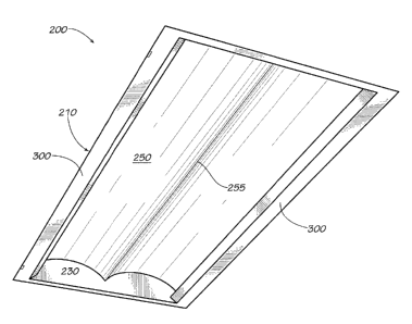
[0028] With reference to Figs. 1-4, in one embodiment a light fixture 100
generally includes a door assembly 200 that is mounted onto a housing 400
positioned
in a ceiling 500. In an embodiment the light fixture 100 may be a recessed
light fixture.
[0029] The door assembly 200 generally includes a door frame 210 formed by
two frame sides 300 and two frame ends 230 (only one frame end is visible in
Fig. 1).
Collectively, the frame sides 300 and frame ends 230 define an opening 240.
The door
frame 210 can be of any dimensions and is not limited to the rectangular-
shaped frame
shown in Fig. 1. A reflector 250 is positioned within the door frame 210 to
span the
opening 240 of the door frame.
[0030] Each frame side 300 supports various components of the door
assembly
200 and provides a rigid construct to ensure that such components remain
oriented
properly relative to each other. In certain embodiments, one or both frame
sides 300
may include the following features, described in more detail below: a slot
310, a
mounting surface 320 for one or more LEDs 325 (shown mounted on printed
circuit
board 328), one or more apertures 330, an angled frame side edge 340, a bottom
edge
350, and a mounting ledge 360 for a reflective kicker 365.
[0031] The slot 310 on each frame side 300 receives an edge of the
reflector 250
to retain the reflector 250 on the door assembly 200 and ensure that the
reflector 250
7
CA 02809555 2013-03-14
retains its intended shape and relative positioning to the LEDs 325 to reflect
light from
the LEDs 325 as desired (described in more detail below).
[0032] The mounting surface 320 for the printed circuit board 328
precisely
positions the one or more LEDs 325 on the board 328 at the proper angle such
that they
direct light onto the reflector 250 at the desired angle(s). The printed
circuit board 328
may be mounted directly on the mounting surface 320 or a thermally insulative
or other
material may be interposed between the mounting surface 320 and the printed
circuit
board 328.
[0033] The apertures 330 receive screws or other fasteners (not shown) to
attach the frame ends 230 to the frame sides 300 to form the door frame 210.
[0034] The angled frame side edge 340 extends upwardly from the bottom
edge
350 and shields the one or more LEDs 325 from direct view when the light
fixture 100 is
installed in the ceiling 500 and prevents light emitted by the one or more
LEDs 325 from
being emitted directly out of the light fixture 100 (i.e., so that almost all
of the light that
ultimately escapes the light fixture 100 does so by reflection off of the
reflector 250).
[0035] The mounting ledge 360 extends from the angled frame side edge 340
to
support and precisely locate a reflective kicker 365 that reflects and thereby
re-directs
light from the one or more LEDs 325 onto the reflector 250.
[0036] The frame sides 300 may be formed (such as by extrusion) of a
metallic
(e.g., aluminum), polymeric or other material that conducts heat away from the
one or
more LEDs 325 mounted on the frame sides 300. Although shown in the figures as
integrally formed, it will be recognized that various portions of frame side
300 could be
8
CA 02809555 2013-03-14
formed separately and then connected to each other by known attachment or
fastening
methods (e.g., adhesives, physical fasteners including but not limited to
screws and
bolts, snap-fittings, etc.).
[0037] The frame sides 300, with some or all of the associated features
discussed above, precisely locate and retain in the desired relative positions
the
reflector 250, one or more LEDs 325 and kicker 365 to allow for consistency in
light
distribution from one light fixture installation to the next.
[0038] Moreover, in some embodiments all of the fixture parts (light
source(s),
reflector(s), heat sink, etc.) are supported by the frame sides 300 of the
door assembly
200. Thus, it is possible easily to retrofit the door assembly 200 into an
existing housing
400 through the use of brackets that span the ends of the housing and engage
the door
frame, such as the frame ends of the door frame. U.S. Patent Publication No.
US-2009-
0207603-A1, the disclsoure of which is incorporated by referenced herein in
its entirety,
describes an example of brackets that could be adapted to retrofit the door
assembly
200 into existing housings 400.
[0039] Other features relate to methods for improving the shipping
efficiency of
the light fixture 100. As explained above, the reflector 250 and frame ends
230 may be
attached to the frame sides 300 and may thus be removable therefrom. In some
embodiments, the reflector 250, frame ends 230 and frame sides 300 are
packaged and
shipped in disassembled form. When disassembled, the reflector 250 may be
collapsible such that it can be compressed (i.e., by pushing down on the
reflector 250 or
allowing the center of the reflector to naturally drop down), which reduces
the height of
9
CA 02809555 2013-03-14
the reflector 250 for shipping, allowing for a thinner shipping container and
thus
improved shipping efficiency. To assemble the light fixture 100, the consumer
removes
the reflector 250, frame sides 300 and frame ends 230, inter alia, from the
shipping
container. The reflector 250 either returns to its original shape (e.g., by
spring action
due to inherent tension in the reflector 250) or the consumer shapes the
reflector by
installing it into the slot 310 on each frame side 300 and attaching the frame
ends 230
to the frame sides 300 as described above. As explained above, once installed,
the
positioning of the reflector 250 relative to the frame sides 300 (and thus to
the one or
more LEDs 325) is precisely determined.
[0040] Embodiments of the reflector 250 used in the door assembly 200
utilize a
reflective optical material and a reflector geometry to realize the benefits
of both a
specular reflective surface and diffuse reflective surface. More specifically,
the reflector
250 is designed to reflect light in a largely diffuse manner to impart a
uniform glow to
the luminous surfaces of the fixture, but is also able to control the
directionality of some
of the light to create an engineered photometric distribution without hotspots
and light
source images.
[0041] Specular surfaces are ones in which reflected light leaves the
surface at
the same angle to the surface normal as the incident light. The output light
distribution
from an example reflector using this type of reflection is represented by the
polar plot
of Figure 5. If such a surface is relatively smooth over an area, the
reflected rays can
form an image. Examples of materials with such surfaces are bathroom mirrors,
polished granite countertops, etc. Specular surfaces can be made to reflect in
quasi-
CA 02809555 2013-03-14
random directions by patterning the surface with a quasi-random shape.
Examples of
such finishes include hammer-tone, patterned microstructures, holographic
microstructures, etc.
[0042] Diffuse surfaces are ones in which reflected light leaves the
surface in all
directions equally, regardless of the direction of the incident light. The
output light
distribution from an example reflector using this type of reflection is
represented by the
polar plot of Figure 6. These surfaces do not reflect images, but also do not
allow for
control of where the reflected light will go. Examples of materials with such
surfaces
are matte paper, carpet, etc.
[0043] Real materials and surfaces are usually not ideal and so the
reflection
characteristics are more complex. Diffuse materials often have relatively
smooth
surfaces and may have a specular component to the reflection (e.g. glossy
magazine
paper or glossy paint). Objects can be imaged in such surfaces, albeit with
potentially
low contrast. Likewise, a seemingly smooth specular surface may reflect light
with some
diffuse component, potentially reducing to what extent the reflected light can
be
controlled. Diffuse surfaces with a significant specular component are
sometimes
termed "semi-specular" and specular surfaces with a significant diffuse
component are
sometimes termed "semi-diffuse."
[0044] In luminaire optics, it is often desirable to make a source seem
less bright
by expanding the luminous area. At the same time, it is often desirable to
control where
the light goes to maximize the effectiveness of the light in the target
application (e.g.
minimize hot-spots, illuminate vertical surfaces in racks, etc.). With
traditional reflective
11
CA 02809555 2013-03-14
materials, it is often not possible to completely obscure the light source
(typically using
diffuse surfaces) while retaining control of the light distribution (typically
using specular
surfaces).
[0045] If the reflector described herein was completely diffuse, then near
the
LEDs the reflector would appear much more luminous than areas further away
from any
LEDs. If the reflector was completely specular, then the output light would be
directional, but the reflector would have images of some LEDs "flashed" at any
given
observation position while the rest of the reflector would appear dark.
[0046] A reflector 250 according to some embodiments of the invention
include
both a reflective optical material and a reflector geometry that collectively
enable the
reflector to impart a diffuse appearance to its surface while at the same time
controlling
some of the reflected light to create a tailored distribution. Such a hybrid
distribution is
represented by the polar plot of Figure 7, which represents some of the light
being
diffusely reflected and other of the light being specularly reflected.
[0047] Embodiments of the reflector 250 include a reflector substrate 370
provided with a semi-specular optical material 375 that forms the optical
surface of the
reflector 250. See generally Figure 8.
[0048] The reflector substrate 370 may be made of any suitable material,
including polymeric materials (e.g., optical grade polyesters, polycarbonates,
acrylics,
etc.) or metallic materials (e.g., prefinished anodized aluminum (e.g. Alanod
Miro),
prefinished anodized silver (e.g. Alanod Miro Silver), painted steel or
aluminum, etc.).
Regardless of the substrate material, the semi-specular optical material 375
may be
12
CA 02809555 2013-03-14
provided on the reflector substrate 370. In some embodiments, the semi-
specular
optical material 375 is adhered to the substrate by an adhesive 380. In other
embodiments, the semi-specular optical material 375 may be extruded onto the
reflector substrate 370. The semi-specular optical material 375 may be
provided on the
reflector substrate 370 either prior or subsequent to bending or thermoforming
the
reflector substrate 370 into the desired reflector geometry.
[0049] In some embodiments, the semi-specular optical material 375 is a
composite material formed of a specular reflective film 385 coated with a
diffuse
coating 390. As seen in Figure 8, the diffuse coating 390 is slightly
transmissive so that
some of the light hitting the diffuse coating 390 is diffusely reflected by
the diffuse
coating 390 whereas other of the light hitting the diffuse coating 390
penetrates
through to the specular reflective film 385 underneath the diffuse coating
390, where it
is specularly reflected. One embodiment of a suitable semi-specular optical
material
375 having a specular reflective film 385 coated with a diffuse coating 390 is
3M's Semi-
Specular Film on Metal, which includes a polymeric specular film (Enhanced
Specular
Reflector or ESR) provided with a diffuse coating. The specular reflective
film 385
should have an extremely high surface reflectivity, preferably, but not
necessarily,
between 96%-100%, inclusive, and more preferably 98.5-100%, inclusive.
[0050] The bulk and surface scattering characteristics of the optical
materials
and surfaces can be varied such that the resulting distribution of the
reflected light is
reflected with a bias towards the forward direction, but no images are formed.
In some
embodiments, the exposed surface of the diffuse coating 390 of the semi-
specular
13
CA 02809555 2013-03-14
optical material 375 is enhanced or otherwise altered (e.g., roughened,
provided with
surface or other patterns, structured, hammer-tone, etc.). In certain
embodiments, one
or more of the semi-specular optical material 375 (including the specular
reflective film
385 and/or the diffuse coating 390) and the reflective substrate 370 is
enhanced or
otherwise altered.
[0051] In some embodiments, the surface enhancements are provided on the
order of 1/4 micron to 1/2 inch. In other embodiments, the surface
enhancements are
provided on the order of 1/2 micron to 100 microns, or even 1 micron to 10
microns. In
yet other embodiments, the surface enhancements are provided on the order of
1/2
micron to 10 microns, or even 10 microns to 100 microns or 100 microns to 1/4
inch.
[0052] As seen in Figure 9, with the semi-specular optical material 375
near the
one or more LEDs 325 only some of the light is reflected diffusely 392. The
rest of the
light is moved forward via "forward transport" 394 (described below) in a
controlled
manner and interacts again with the inner part of the reflector 250 (i.e.,
towards the
apex of the reflector 255) where it is reflected into the desired beam. Since
this second
reflection also has a diffuse component, the whole reflector 250 has luminance
from
any given observation position. If the forward light was from specular
reflection only,
then from a given observation position, there would be sharp transitions in
the
luminance of the reflector surface across the reflector. At worst this would
look like
images of the one or more LEDs 325 and at best it would look like a hotspot on
the
reflector 250. By using a less defined "forward-transport" reflection, these
hotspots are
reduced and the transition between high and low luminance areas across the
reflector
14
CA 02809555 2013-03-14
are blended together. If done correctly, the transitions can become nearly
indistinguishable from areas where the luminance is from the diffuse component
only.
[0053] For the purposes of this description, when a surface is illuminated
from a
given direction (defined as east), "forward-transport" is the amount of
reflected light in
the western quarter-sphere minus the amount of reflected light in the eastern
quarter-
sphere all divided by the total amount of reflected light. With this
definition, a purely
specular material will have a transport ratio of 1 and a purely diffuse
material will have a
transport ratio of 0.
[0054] The number of times that light is reflected by the reflector 250
(and thus
the tailoring of the light's distribution) is also dependent on the geometry
of the
reflector, particularly the reflector's radius of curvature, which may range
between 9-
14" inclusive and more particularly around 11.5" in some embodiments. In some
embodiments, the curvature is a freeform surface with a plurality of radii of
curvature.
Given the indirect nature of light emission from the fixture, the light will
always reflect
at least once before exiting the fixture. The light may reflect any number of
times
before exiting the fixture, but typically will reflect between 1 to 3 times.
[0055] The size and geometry of the apex 255 of the reflector 250 (defined
herein as the area where the two curved portions of the reflector 250 meet)
also
dictates how the light is reflected by the reflector 250. While the Figures
illustrate a
reflector 250 having a relatively pointed apex 255, the apex 255 can have a
myriad of
other geometries, including, but not limited to, those disclosed in PCT
Application
PCT/US2011/24922 (Publication No. WO 2011/100756 Al), the disclsoure of which
is
CA 02809555 2013-03-14
incorporated by referenced herein in its entirety, in which the optical
elements
described therein can obviously assume more of a linear nature depending on
the
dimensions of the reflector 250. The apex 255 of the reflector 250 may be
recessed
within the door frame 210 or terminate coplanar with the door frame 210. In
other
embodiments, the apex 255 may extend below the plane of the door frame 210
(and
thus the plane of the ceiling 500).
[0056] The reflector described herein is by no means limited to use in the
recessed fixture illustrated in the Figures. Rather, the reflector can be
adapted for use
in any type of indirect lighting fixture. For example, the reflector may be
installed
directly into a ceiling without the use of a housing, e.g., by installing it
directly onto the
1-grid of a ceiling.
[0057] Different arrangements of the components depicted in the drawings
or
described above, as well as components and steps not shown or described are
possible.
Similarly, some features and subcombinations are useful and may be employed
without
reference to other features and subcombinations. Embodiments of the invention
have
been described for illustrative and not restrictive purposes, and alternative
embodiments will become apparent to readers of this patent. Accordingly, the
present
invention is not limited to the embodiments described above or depicted in the
drawings, and various embodiments and modifications can be made without
departing
from the scope of the claims below.
16