Note: Descriptions are shown in the official language in which they were submitted.
1
MECHANICAL WAVE GENERATOR AND METHOD THEREOF
[0001]TECHNICAL FIELD
[0002] This invention relates to devices for generating mechanical waves
and methods
thereof.
BACKGROUND
[0003] A "mechanical wave" is a disturbance that propagates through a
medium due to
the restoring forces it produces upon deformation of the medium. Solids,
liquids, gases, and gels
are examples of media through which a mechanical wave may travel.
[0004] If desired, the energy of a mechanical wave can be exploited to
deform and
potentially fracture an object placed in the medium. For example, high
intensity compression
pulses (i.e., a brief wave of great amplitude) can be sent in the body of a
patient to break a
kidney stone apart.
[0005] One protocol for kidney stone destruction consists of emitting a
compression
pulse having a sufficient amount of energy for traveling through the body,
reaching the stone,
and potentially rupturing the kidney stone upon contact. Machines used in
medical kidney stone
destruction are known in the art as lithotripters. The external lithotripters
send externally-applied,
focused, high-intensity compression pulses toward the kidney stone. As the
high intensity
compression pulses travel through the body of the patient, non-linear effects
eventually deform
these pulses into Shockwaves. When a Shockwave encounters a non-homogeneity
such as the
kidney stone, a relatively large amount of energy is transferred from the
Shockwave to the
kidney stone in a (relatively) very short period of time. Ideally, this energy
transfer is sufficient
to break enough of the bonds between the stone particles
CA 2809746 2017-12-22
CA 02809746 2013-02-27
WO 2012/025833
PCT/1B2011/002701
2
to destroy the stone. With external lithotripters, the location of the kidney
stone within
the body of the patient must be known in order to direct the high-intensity
compression pulses toward the kidney stone.
[0006] Despite
their widespread use, conventional lithotripters are
cumbersome apparatuses. First, they have the drawbacks of potentially damaging
tissue adjacent to the kidney stone and producing large kidney stone
fragments.
Second, they have a limited focal length. Occasionally, conventional machines
even
fail to fragment the hardest kidney stones. Finally, conventional
lithotripters often
require the inclusion of apparatuses such as fluoroscopy (x-ray) or ultrasound
machines for locating the kidney stone.
[0007] Montaldo
et al. 'Generation of vely high pressure pulses with 1-bit
time reversal in a solid waveguide', J. Acoust. Soc. Am. 110(6), December 2001
have
developed a way to focus high amplitude pressure pluses at predetermined
locations
in a fluid. The system of Montaldo et al. works according to the time-reversal
mirror
concept, which exploits the temporal reversibility (or reciprocity) of the
wave
equation of motion. Reciprocity says that if the wave equation has a solution,
the time
reversal (using a negative time) of that solution is also a solution of the
wave
equation.
[0008] The
system S proposed by Montaldo et al., shown in Fig. 1, is
composed of seven small independent bi-directional piezoelectric transducers T
glued
to one end of an aluminum bar (waveguide), which acts as a reverberative
cavity RC.
The transducers T can both emit and receive mechanical waves. The walls of the
reverberative cavity RC are in contact with the air while the end of the
reverberative
cavity RC distal to the transducers T lies in water. In their experiment,
Montaldo et al.
use a source placed in the water to emit a pressure pulse toward the
reverberative
cavity RC. The pressure pulse is, after propagation through the reverberative
cavity
RC, recorded by each of the transducers T. As it travels through the
reverberative
cavity RC, the pressure pulse P undergoes some deformation due to
reverberations R
inside the reverberative cavity RC, as described below. The transducers T
convert the
recorded pressure pulse into an electric signal. The signal of each transducer
T is then
time reversed and processed to excite the same transducer T. The mechanical
waves
produced by each transducer T propagate through the reverberative cavity RC,
by
CA 02809746 2013-02-27
WO 2012/025833
PCT/1B2011/002701
3
reverberations R, toward the other end of the reverberative cavity RC, and
emerge at
that end thereof to produce a focused pressure pulse W2 (shown in Fig. 2) at
the
location of the source.
[0009] As shown
in Fig. 2, when a mechanical wave W1 created by one or
more of the transducers T is propagated inside the cavity RC, reverberations R
at the
wall of the cavity RC redirected it to the core of the cavity RC. The
reverberations R
are a consequence of the difference of acoustic impedance between the
reverberative
cavity RC and the surrounding air. Since the wall reverberations R are with
almost no
energy loss, the mechanical wave WI can travel inside the reverberative cavity
RC
without undergoing major attenuation. Each reverberation R creates the
illusion of
having originated from a virtual transducer VT. The assembly of these virtual
transducers VT is perceived by an observer at a focal point FP as a source of
great
dimension, although only a limited number of real transducers RT is used.
[0010] As a
consequence, the technology proposed by Montaldo et al. uses a
limited number of low-power transducers to temporally and spatially
concentrate
trains of low amplitude waves in order to obtain a high amplitude and short-
lasting
focused wave. The spatial focalisation is made possible by the reverberating
nature of
the cavity while the temporal compression is made possible by the time
reversal
operation. Montaldo et al. sends the pulses at predetermined locations which
correspond to locations where a source was originally positioned.
[0011] Montaldo
et al.'s device reaches some limits, especially when applied
to lithotripsy. A simple calculation can show that their proposed device is
not capable
of reaching focal distances compatible with applications where the target is
typically
remote from the wave emitting device. Further, to reach typical focal
distances
required for kidney stones destruction in human subjects, one would need to
construct
a device having an unrealistic number of transducers or else have the
reverberative
cavity of a cumbersome length or diameter. A device of such a size is far from
Montaldo et al.'s main object which was to present a simple and compact
alternative
to current commercial lithotripters, and this probably explains why there is
no
evidence of the construction of such a device in literature.
[0012] Thus, in
summary, in terms of the use of wave generators of high
intensity acoustic pulses with possible applications in lithotripsy, it is
believed that
CA 02809746 2013-02-27
WO 2012/025833
PCT/1B2011/002701
4
conventional technology has reached its limits in what it will allow, and the
disadvantages noted above remain. While the wave generator proposed by
Montaldo
et al. may assist in ameliorating the situation, room for improvement would
nonetheless still exist.
SUMMARY
[0013] It is an
object of the present invention to ameliorate at least some of the
inconveniences mentioned above. It is also an object of the present invention
to
provide an improved wave generator that generates mechanical waves by, amongst
other things, exploiting the dispersive properties of a waveguide. It is also
an object of
the invention to provide an improved wave generator that generates high
intensity
pulses from low power components. It is also an object of the invention to
provide an
improved wave generator that generates one or more mechanical waves as desired
and
chosen by a user, independently of an emitting source in the environing medium
of
the wave generator.
[0014] In a first
aspect, the wave generator of the present invention includes
an elongated dispersive waveguide and a source covering at least partially one
end of
the waveguide. The source is programmable to generate one or more mechanical
waves in the dispersive waveguide. Because the waveguide is dispersive, a
mechanical wave gets typically distorted as it travels through the waveguide.
When
reaching the end of the waveguide distal to the source, at least components
waves
composing the mechanical waves recombine due to the dispersive effects to form
a
desired wave that is emitted in the medium in contact with the end of the
waveguide
distal to the source. Because the source is programmable and at least some of
the
dispersive properties of the waveguide can be predetermined, the mechanical
wave
generated in the dispersive waveguide can be determined so as to form, when
recombined, an emitted wave as chosen by the user. The device of the present
invention works by beneficially exploiting dispersion. Dispersion is an
intrinsic
property of the geometry and composition of the waveguide.
[0015] Any
waveform can be decomposed into a finite sum of component
waves. The components waves each include a function in time and a function in
space. Each component wave has an associated frequency, magnitude and phase in
CA 02809746 2013-02-27
WO 2012/025833
PCT/1B2011/002701
time and an associated deformation field in space. A specific shape of the
deformation
field corresponds to a mode of the waveguide. Thus for the purposes of this
application, we will consider that a component wave has an associated
frequency, an
associated magnitude, an associated phase and an associated mode of the
waveguide.
5 As a consequence, two component waves can have a same frequency and excite
different modes. Two component waves can also have different frequencies and
excite
a same mode. Two component waves can also have different frequencies and
excite
different modes. For the purpose of this application, we will consider that
the modes
are longitudinal modes propagating in a longitudinal axis of an elongated
waveguide.
For a mechanical wave traveling in the waveguide, a component wave has an
associated propagation velocity. When the propagation velocity in the
waveguide
depends on the frequency and the mode of the component wave, the waveguide is
qualified as 'dispersive'. Thus, a dispersive waveguide compels a relative
phase
difference of the component waves of a mechanical wave, which transforms a
pulse
(ordered phase component waves) into an oscillation train having a lower
amplitude
and a longer temporal span (rearranged component waves).
[0016] An example of dispersion in a dispersive waveguide is shown in
Figs.
3A-3F. It is contemplated that the dispersion would be similar in a dispersive
medium
other than a waveguide. A pulse P (characterized by its amplitude A
distribution in
function of time t, as shown in Fig. 3A) has a plurality of component waves
(shown in
Fig. 3B), each of them being characterized by their unique frequency f, their
associated phase çf (or relative phase) (shown Fig. 3C), their magnitude M
(shown in
Fig. 3B) and their mode. The pulse P becomes a dispersed wave DW
(characterized
by its amplitude A distribution in function of time t, as shown in Fig. 3D)
after
propagation in the dispersive waveguide. The dispersed wave DW has the same
component waves (shown in Fig. 3E) characterized by the same frequencies f,
the
same magnitude M (shown in Fig. 3E) but different associated phases q (shown
in
Fig. 3F). As shown in Figs. 3C and 3F, the dispersive properties of the
waveguide
have introduced a phase shift between the component waves traveling through
the
dispersive waveguide. It is assumed that the waveguide is dispersive with no
attenuation, as illustrated in Figs. 3B and 3E where a maximum magnitude M1 is
the
same for in Figs. 3B and 3E. It is contemplated that some attenuation could be
present.
CA 02809746 2013-02-27
WO 2012/025833
PCT/1B2011/002701
6
[0017] The inventors have realized that, when the dispersive
properties of a
waveguide are known, it is possible to program a source so as to generate a
mechanical wave where the component waves of the mechanical wave have
associated phases such that, once phase shift is introduced by the dispersive
waveguide, the mechanical wave recombines at the other end of the waveguide
into
the desired mechanical wave. The wave generator of the present invention works
according to this principle, by exploiting the dispersive properties of a
waveguide to
generate desired mechanical waves. Since the emitted mechanical waves are
chosen
by the user, in some cases, the wave generator can also be used as a 'passive
amplifier' to generate high amplitude acoustic pulses.
[0018] Contrary to the present device, the wave generator of Montaldo
et al.
exploits reverberations, and not dispersion, to amplify mechanical waves.
However, it
should be noted that Montaldo et al. in 'Generation of very high pressure
pulses with
1-bit time reversal in a solid waveguide', J. Acoust. Soc. Am. 110(6),
December
2001, refer wrongly to reverberation as a 'dispersion'. Indeed, similarities
between
this device and the one previously described by their colleagues Roux et al.
in 'Time-
reversal in an ultrasonic waveguide', Applied Physics Letters 70(14), February
1997,
show that the amplification is attributable to reverberations rather than to
dispersion.
It may be that some actual dispersion does occur, but as Montaldo et al.
noted, this
dispersion is compensated for (as opposed to being exploited by) by the time
reversal
operation. Thus, Montaldo et al. rely on reverberation and not dispersion to
operate
their device.
[0019] To generate the desired mechanical waves, the dispersive
properties of
the waveguide are predetermined. Knowing the dispersive properties consists in
knowing the relationships between component waves and propagation velocities
in
the waveguide. A unique calibration step is sufficient to determine the
dispersive
properties. The calibration step can be done experimentally or analytically.
In one
example, the finite element method is used to determine the dispersion
relationships.
In another example, a hydrophone can be used to experimentally determine the
dispersive properties.
[0020] Initial calibration of the wave generator is done independently
of an
emitting source present in the medium. Montaldo et al., however, rely on an
emitting
CA 02809746 2013-02-27
WO 2012/025833
PCT/1B2011/002701
7
source to calibrate initially their device. Further, the wave generator of the
present
invention uses the same calibration whatever the focal point is, whereas
Montaldo et
al. require a moving emitting source to calibrate different focal points. In
addition, the
present device can generate selected desired mechanical output waves that are
designed according to the application the user intends to use the mechanical
waves
for, contrary to Montaldo et al. which device only generates mechanical output
waves
according the emitting source.
[0021]
Furthermore, because the present invention uses a source (e. g. a single
transducer) covering totally or partially an end of the waveguide, the
mechanical
waves generated can be one dimensional. The device of Montaldo et al. has
instead a
plurality of bi-directional transducers covering only partially the end of the
reverberative cavity RC (as can be seen in Fig. 1) and this arrangement
generates
multi-dimensional waves. Opposite to what Montaldo et al. implies, a one-
dimensional source (e. g. single transducer) can as much exploit dispersion as
a
tridimensional source (e. g. plurality of transducers), and that even when the
wavelength of the mechanical wave is small compared to the waveguide diameter.
For
example, Puckett et al. in 'A time-reversal mirror in a solid circular
waveguide using
a single, time-reversal element', ARLO 4(2), April 2003, cleans the echoes
present in
a buffer rod placed between a target medium and a transducer by using the
temporal
reverse mirror method in order to cancel the undesired effects of dispersion.
Thus,
since it is possible to eliminate the phase difference of a signal caused by
dispersion
with only one transducer covering a whole end of the buffer rod, it is as much
possible
to efficiently exploit that dispersion in order to increase tenfold a one-
dimensional
source power.
[0022] Because the present wave generator can use a one-dimensional source,
the wave generator can generate planar waves, which can propagate at
relatively long
distances away from the emitting end of the waveguide. In comparison, the
device of
Montaldo et al. generates pulses focused at locations relatively close to the
emitting
end of the waveguide.
[0023] The present wave generator can generate planar waves which excite a
single mode. In some cases, the wave generator can excite solely the
fundamental
(first) mode of the waveguide. Although the present wave generator may be
capable
CA 02809746 2013-02-27
WO 2012/025833
PCT/1B2011/002701
8
of exciting multiple modes, the present wave generator does not require to
excite
more than one mode.
[0024] Thus, in
a first aspect, as embodied and broadly described herein, the
present invention provides a wave generator for emitting a desired mechanical
output
wave into a medium. The generator comprises a wave emitter including an
elongated
dispersive waveguide having a first end and a second end. When in operation
the
second end is at least partially in contact with the medium. A source is
operatively
connected to the first end of the dispersive waveguide covering at least
partially a
surface area of the first end. The source is operative to generate a
mechanical input
wave in the dispersive waveguide based on electrical signals input to the
source. A
signal generator is in operative connection with the source. The signal
generator is
operative to create the electrical signals converted by the source into the
mechanical
input wave in the dispersive waveguide. A computer is in operative connection
with
the signal generator, the computer having a processor and a machine-readable
storage
medium. The machine-readable storage medium contains instructions that when
executed by the processor cause the signal generator to create electrical
signals
converted by the source into the mechanical input wave. The mechanical input
wave
has at least two component waves. Each of at least two of the component waves
has a
unique predetermined propagation velocity through the dispersive waveguide.
The
mechanical input wave is constructed (i) independently of data related to a
mechanical
wave received from a source in the medium and (ii) taking into account the
different
predetermined propagation velocities of the at least two component waves so
that the
at least two component waves combine at least partially with each other at the
second
end of the dispersive waveguide to form the desired mechanical output wave
emitted
into the medium.
[0025] In some
embodiments, the desired mechanical output wave has an
amplitude greater than an amplitude of the mechanical input wave, and in some
other
embodiments the desired mechanical output wave is temporally compressed
relative
to the mechanical input wave. A constructive recombination can occur when
slower
component waves of the mechanical input wave are sent in the dispersive
waveguide
before faster component waves, at time intervals that compensate for the
relative
phase shift introduced by the dispersive waveguide. The slower and the faster
CA 02809746 2013-02-27
WO 2012/025833
PCT/1B2011/002701
9
component waves interact with each other at a specific location in the
dispersive
waveguide. When the interaction is constructive (i.e. when the components
waves
have both a positive magnitude), the resultant mechanical wave has an
increased
amplitude. It is contemplated that, in other embodiments, a destructive
recombination
(or another type of combination of the two component waves) could be preferred
to
create specific output mechanical waves. Resulting to the interaction, one can
create a
desired mechanical output wave that is temporally compressed after traveling
through
the dispersive waveguide.
[0026] By
programming the source so as to have slower component waves
sent before faster component waves, the constructive interaction can be used
for the
generation of high intensity pulses. Whereas dispersion is typically avoided
in wave-
guiding devices, the inventors have found a way to use and exploit a
dispersive
waveguide as a wave amplifier (or wave compressor). As a consequence, in the
device
proposed by the inventors, it is no longer required to have high energy
components to
generate high intensity mechanical waves. For example, a low voltage
transducer with
large frequency domain is sufficient to create high intensity pulses. In some
cases, it is
even possible to create a high intensity pulse having an amplitude over ten
times
larger than that of a train of low intensity waves input into the dispersive
waveguide.
[0027] In some
embodiments, the at least two component waves have an
associated frequency and an associated mode of the waveguide. The at least two
component waves have different associated frequencies. The at least two
component
waves have a same associated mode.
[0028] In some
embodiments, the same associated mode is a single mode of
the waveguide.
[0029] In some embodiments, the single mode is a fundamental longitudinal
mode of the waveguide.
[0030] In other
embodiments, the at least two component waves have different
associated modes. The at least two component waves have a same associated
frequency.
[0031] In some embodiments, the source is a transducer.
CA 02809746 2013-02-27
WO 2012/025833
PCT/1B2011/002701
[0032] In some
embodiments, the source has a frequency bandwidth. The at
least two component waves have each an associated frequency. The associated
frequencies of the at least two component waves are within the frequency
bandwidth
of the source. a frequency bandwidth of the source, an attenuation coefficient
of the
5 dispersive
waveguide is such that the wave emitter has a positive gain. To ensure that
the source generates mechanical waves that have frequency components in the
dispersive region of the waveguide, it is preferable to have the frequency
bandwidth
of the source at least partially within the dispersive region of the
waveguide.
[0033] In some
embodiments, the source covers at least entirely the surface
10 area of the
first end of the dispersive waveguide. When the source covers entirely the
surface area of the first end of the dispersive waveguide, little
reverberation interfere
with the mechanical wave traveling through the dispersive waveguide, and the
output
mechanical wave corresponds to the desired mechanical wave as computed from
the
dispersion relations. While Montaldo et al. rely on reverberations to amplify
the
mechanical waves, reverberations are not exploited for the operation of the
wave
generator of the present invention.
[0034] In some
embodiments, the dispersive waveguide has a constant cross-
section. In applications where the dispersive waveguide has a constant cross-
section,
reverberations are limited.
[0035] In some embodiments, the wave generator further comprises at least
one of an acoustic impedance coupler and an acoustic lens operatively
connected to
the second end of the dispersive waveguide. To optimize energy transmission of
the
output mechanical wave between the dispersive waveguide and the medium, the
acoustic impedance coupler can be positioned between the wave emitter and the
medium. The acoustic impedance coupler is used to match the acoustic impedance
of
the dispersive waveguide with the acoustic impedance of the medium, thereby
minimizing reflection between the two. In some embodiments, the acoustic
impedance coupler includes at least one layer. The at least one layer has an
acoustic
impedance intermediate to an acoustic impedance of the dispersive waveguide
and to
an acoustic impedance of the medium. The at least one layer is chosen as a
function of
its acoustic impedance so as to maximize energy transmission of the desired
mechanical output wave between the second end of the dispersive waveguide and
the
CA 02809746 2013-02-27
WO 2012/025833
PCT/1B2011/002701
11
medium. An acoustic lens can be used to geometrically focus the desired
mechanical
output wave. In some applications where a target is at a known location and it
is
desired to generate spatially concentrated mechanical waves, the desired
mechanical
output wave can be further geometrically focused.
[0036] In some embodiments, within a frequency bandwidth of the source, an
attenuation coefficient of the dispersive waveguide is such that the wave
emitter has a
positive gain. For some applications, the dispersive waveguide is chosen to
have a low
attenuation coefficient at frequencies of interest in order to maximize gain.
The
frequencies of interest are the frequencies comprised within the source's
frequency
bandwidth which are also frequencies for which the waveguide is dispersive.
The
attenuation coefficient describes the extent to which the intensity of a wave
is reduced
as it passes through a specific material (i.e., the waveguide) due to internal
friction
and heat losses.
[0037] In some
embodiments, the dispersive waveguide is one of the group
consisting of a metal and a ceramic. Metals and ceramic have preferably a low
attenuation coefficient of the frequencies of interest. A material for the
dispersive
waveguide is preferably chosen to have a high Poisson coefficient, low
attenuation
coefficient, and low propagation velocity. An acoustic impedance is preferably
as
close as possible to that of the source and the medium in order to maximize
transmission of energy.
[0038] In some
embodiments, an aspect ratio of the dispersive waveguide is at
least 10. For a cylindrical waveguide, the aspect ratio could preferably be
approximately be between 10 and 1000. A somewhat large aspect ratio enhances
amplification in embodiments where high intensity mechanical waves are
desired. The
longer the rod, the more amplification can be obtained. The waveguide has a
length
that preferably allows a significant amplification gain and allows the user to
identify
the signal from noise at the calibration step. A somewhat low aspect ratio has
for
consequence that the waveguide may be weakly dispersive.
[0039] In some
embodiments, the desired mechanical output wave is generally
planar. In applications where the source covers most or more of the first end
of the
CA 02809746 2013-02-27
WO 2012/025833
PCT/1B2011/002701
12
dispersive waveguide, the desired mechanical output wave is generally planar
(one
dimensional).
[0040] In some
embodiments, the desired mechanical output wave is
unfocused. In applications where planar mechanical waves are generated, the
desired
mechanical output wave is unfocused.
[0041] In some embodiments, the desired mechanical output wave is
focused.
In one example, the desired mechanical output wave is geometrically focused.
In
another example, diffraction effects at the second end of the dispersive
waveguide are
used to focus energy at a predetermined spatial location within the medium.
[0042] In other embodiments, the dispersive waveguide is curved along its
length at least in part between the first end and the second end.
[0043] In yet
other embodiment, the dispersive waveguide has a radius of
curvature at least an order of magnitude of wavelengths of the at least two
component
waves.
[0044] In some embodiments, the dispersive waveguide is flexible. By
'flexible' it should be understood a material capable of being (relatively
easily ¨
during the intended application of the device) bent or curved, but not
necessarily
foldable. A waveguide that is flexible can be used for space saving or when
reaching
places with restricted access. In some cases, the procedure requires that the
mechanical waves be emitted in the vicinity of a target and/or for increasing
the
transmission of energy. Thus, a flexible waveguide might allow for the
positioning of
the wave emitter right in front of the target, even when the target may be
difficult to
access.
[0045] In some
embodiments, the wave generator further comprises an
amplifier operatively connected to the signal generator. The amplifier is
operative to
modify an amplitude of at least a portion of the electric signals input to the
source. In
one example, the amplifier is used to saturate the electric signals input to
the source.
[0046] In some
embodiments, the source is a bi-directional transducer and is
further operative to generate electrical signals from a reverse direction
mechanical
CA 02809746 2013-02-27
WO 2012/025833
PCT/1B2011/002701
13
wave. The reverse direction mechanical wave propagates through the waveguide
from
the second end toward the first end of the waveguide. The wave generator
further
comprises a switch in operative connection with the bi-directional transducer
and the
coupler. The switch separates input electric signals from output electric
signals to the
hi-directional transducer. A digitizer is in operative connection with the
switch and
with the computer. The digitizer is operative to digitize the output
electrical signals. In
some applications, for example where the location of a target is to be known,
it is
possible to use a bi-directional transducer for sensing (in addition to
emitting
mechanical waves) perturbations of the medium (or environment). When a
mechanical wave is sent into a medium having a non-homogeneity (such as a
kidney
stone in the body), the non-homogeneity reflects this wave. A wave emitter
having
reception capability is able to detect that reflected wave and, and with the
help of the
computer, a position of the non-homogeneity can be calculated.
[0047] In
another aspect, a wave generator for emitting a desired mechanical
output wave into a medium is provided. The wave generator comprises a wave
emitter
including an elongated dispersive waveguide having a first end and a second
end.
When in operation the second end is at least partially in contact with the
medium. A
source is operatively connected to the first end of the dispersive waveguide
and covers
at least partially a surface area of the first end. The source is operative to
generate a
mechanical input wave in the dispersive waveguide based on electrical signals
input
to the source. A signal generator is in operative connection with the source.
The signal
generator is operative to create the electrical signals convertible by the
source into the
mechanical input wave in the dispersive waveguide. A computer is in operative
connection with the signal generator. The computer has a processor and a
machine-
readable storage medium. The machine-readable storage medium contains
instructions
that when executed by the processor cause the signal generator to create
electrical
signals convertible by the source into the mechanical input wave. The
mechanical
input wave has at least two component waves. Each of the at least two
component
wave has a unique associated predetermined propagation velocity through the
dispersive waveguide. The at least two component waves have a first relative
phase
shift. The first relative phase shift is determined so as to be become, at the
second end
of the dispersive waveguide, a second relative phase shift different from the
first
CA 02809746 2013-02-27
WO 2012/025833
PCT/1B2011/002701
14
relative phase shift owing to the predetermined propagation velocities through
the
dispersive waveguide of the at least two component waves.
[0048] In some
embodiments, the mechanical input wave has a first
amplitude. The desired mechanical output wave has a second amplitude. The
second
relative phase shift is determined so that the second amplitude is greater
than the first
amplitude.
[0049] In some
embodiments, the at least two component waves have an
associated frequency and an associated mode of the waveguide. The at least two
component waves have different associated frequencies, and the at least two
component waves have a same associated mode. In yet other embodiments, the at
least two component waves have different associated modes, and the at least
two
component waves have a same associated frequency.
[0050] In yet
another aspect, a method of emitting a desired mechanical output
wave into a medium is provided. The method comprises providing an elongated
dispersive waveguide having a first end and a second end. The second end is at
least
partially in contact with the medium. The method comprises determining the
desired
mechanical output wave; determining a mechanical input wave. The mechanical
output wave has at least two component waves. Each of the at least two
component
waves having a unique associated predetermined propagation velocity through
the
dispersive waveguide. At least two of the component waves have different
predetermined propagation velocities through the dispersive waveguide. The
mechanical input wave when inputted at the first end of the dispersive
waveguide and
once having propagated through the dispersive waveguide combine at least
partially at
the second end of the dispersive waveguide to form the desired mechanical
output
wave. The mechanical input wave is constructed (i) independently of data
related to a
mechanical wave received from a source in the medium and (ii) taking into
account
the different predetermined propagation velocities of the at least two
component
waves. The method comprises generating the mechanical input wave at the first
end of
the dispersive waveguide; allowing the mechanical input wave to propagate
through
the dispersive waveguide toward the second end; combining the mechanical input
wave to form the desired mechanical output wave at the second end of the
dispersive
waveguide owing to differences in the predetermined propagation velocities of
the at
CA 02809746 2013-02-27
WO 2012/025833
PCT/1B2011/002701
least two component waves; and emitting the desired mechanical output wave
into the
medium at the second end of the dispersive waveguide.
[0051] In an
additional aspect, the method comprises combining the
mechanical input wave having a first duration in time to form the desired
mechanical
5 output wave
having a second duration in time includes shortening the first duration in
time into the second duration in time.
[0052] In a further aspect, the method comprises combining the
mechanical
input wave to form the desired mechanical output wave includes combining the
mechanical input wave having a first amplitude to form the desired mechanical
output
10 wave having
a second amplitude. The second amplitude is greater than the first
amplitude.
[0053] In an
additional aspect, the at least two component waves have an
associated frequency and an associated mode of the waveguide. The at least two
component waves have different associated frequencies. The at least two
component
15 .. waves have a same associated mode.
[0054] In a
further aspect, the same associated mode is a single mode of the
waveguide.
[0055] In some
embodiments the single mode is a fundamental longitudinal
mode of the waveguide.
[0056] In an additional aspect, the at least two component waves have each
an
associated frequency and an associated mode of the waveguide. The at least two
component waves have different associated modes. The at least two component
waves
have a same associated frequency.
[0057] In an additional aspect, the source is a transducer.
[0058] In a further aspect, the source has a frequency bandwidth. The at
least
two component waves have each an associated frequency. The associated
frequencies
of the at least two component waves are within the frequency bandwidth of the
source.
CA 02809746 2013-02-27
WO 2012/025833
PCT/1B2011/002701
16
[0059] In an
additional aspect, the source covers at least an entirety of the
surface area of the first end of the dispersive waveguide.
[0060] In a
further aspect, the dispersive waveguide has a constant cross-
section.
[0061] In an additional aspect, the method further comprises emitting the
desired mechanical output wave in at least one of an acoustic impedance
coupler and
an acoustic lens before emitting the desired mechanical output wave in the
medium.
[0062] In a
further aspect, the acoustic impedance coupler includes at least
one layer before emitting the desired mechanical output wave in the medium.
The at
least one layer has an acoustic impedance intermediate to an acoustic
impedance of
the dispersive waveguide and to an acoustic impedance of the medium. The at
least
one layer is arranged as a function of its acoustic impedance so as to
maximize energy
transmission of the desired mechanical output wave between the second end of
the
dispersive waveguide and the medium.
[0063] In an additional aspect, within a frequency bandwidth of the source,
an
attenuation coefficient of the dispersive waveguide is such that the wave
emitter has a
positive gain.
[0064] In a
further aspect, the dispersive waveguide is one selected from the
group consisting of a metal and a ceramic.
[0065] In an additional aspect, an aspect ratio of the dispersive waveguide
is at
least 10.
[0066] In an
additional aspect, emitting the desired mechanical output wave
into the medium includes emitting the desired mechanical output wave as a
generally
planar wave.
[0067] In a further aspect, emitting the desired mechanical output wave
into
the medium includes emitting the desired mechanical output wave unfocused in
the
medium.
CA 02809746 2013-02-27
WO 2012/025833
PCT/1B2011/002701
17
[0068] In an
additional aspect, emitting the desired mechanical output wave
into the medium includes emitting the desired mechanical output wave focused
in the
medium.
[0069] In a
further aspect, the dispersive waveguide is curved along its length
at least in part between the first end and the second end.
[0070] In yet a
further aspect, the dispersive waveguide has a radius of
curvature at least an order of magnitude of wavelengths of the at least two
component
waves.
[0071] In an additional aspect, the dispersive waveguide is flexible.
[0072] In a further aspect, the method further comprises determining a cut-
off
amplitude; saturating the input electrical signal to the cut-off amplitude to
become a
saturated signal; and amplifying at least a portion of the saturated signal,
before
inputting the input electrical signal to the source.
[0073] In an
additional aspect, generating the mechanical input wave at the
first end of the dispersive waveguide includes: generating an input electrical
signal
corresponding to the mechanical input wave; and inputting the input electrical
signal
to a source disposed at the first end of the dispersive waveguide. The source
transforms the input signal into the mechanical input wave.
[0074] For the purpose of this application, the term "wave", as used
herein,
includes all mechanical waves, i.e., waves that propagate through a medium due
to
restoring forces they produce upon deformation of the medium. The term
"component
waves" refers to functions of space and time on which a mechanical wave can be
decomposed. The term "medium", as used herein, refers to any substance (e.g.
gas,
liquid, solid, gel, non-biological or biological material) that allows for the
propagation
of a mechanical wave through it. The term "waveguide", as used herein, refers
to a
structure that conveys mechanical waves between its endpoints. The term
"shockwave", as used herein, refers to a region of abrupt change of pressure
that
moves a wave front at a relatively rapid velocity though a medium. The term
"acoustic", as used herein, refers to mechanical waves in gases, liquids, and
solids at
frequencies in the range of the sound, ultrasound and infrasound. The term
CA 02809746 2013-02-27
WO 2012/025833
PCT/1B2011/002701
18
"dispersion", as used herein, refers to a physical property of a waveguide by
which
component waves have different propagation velocities through that waveguide.
The
term "source" refers to any element capable of generating a generally planar
longitudinal mechanical wave.
[0075] Embodiments of the present invention each have at least one of the
above-mentioned objects and/or aspects, but do not necessarily have all of
them. It
should be understood that some aspects of the present invention that have
resulted
from attempting to attain the above-mentioned objects may not satisfy these
objects
and/or may satisfy other objects not specifically recited herein.
[0076] Additional and/or alternative features, aspects, and advantages of
embodiments of the present invention will become apparent from the following
description, the accompanying drawings, and the appended claims.
BRIEF DESCRIPTION OF THE DRAWINGS
[0077] For a better understanding of the present invention, as well as
other
aspects and further features thereof, reference is made to the following
description
which is to be used in conjunction with the accompanying drawings, where:
[0078] Figure 1 is a perspective view of a wave generator used in the
prior art;
[0079] Figure 2 is an illustration of reverberations inside the wave
generator
of Fig. 1;
[0080] Figure 3A is a graph of a pulse P (amplitude A vs. time t);
[0081] Figure 3B is a graph of frequency components of the pulse P of
Fig.
3A (magnitude M vs. frequency]);
[0082] Figure 3C is a graph of phases of the frequency components of
the
pulse P of Fig. 3A (phase 0 vs. frequency]);
[0083] Figure 3D is a graph of a dispersed wave DW (amplitude A vs. time
t);
[0084] Figure 3E is a graph of frequency components of the dispersed
wave
DW of Fig. 3D (magnitude M vs. frequency]);
CA 02809746 2013-02-27
WO 2012/025833
PCT/1B2011/002701
19
[0085] Figure 3F is a graph of phases of the frequency components of the
dispersed wave DW of Fig. 3D (phase 0 vs. frequency]);
[0086] Figure 4 is a wave emitter according to a first embodiment of the
invention;
[0087] Figure 5 is an embodiment of a waveguide for the wave emitter of
Fig.
4;
[0088] Figure 6 is yet another embodiment of a waveguide for the emitter of
Fig. 4.
[0089] Figure 7 is another embodiment of a waveguide for the wave emitter
of
Fig. 4;
[0090] Figure 8 is a wave emitter according to a second embodiment of the
invention;
[0091] Figure 9 is the wave emitter of Fig. 4 with an acoustic impedance
coupler;
[0092] Figure 10 is the wave emitter of Fig. 4 with an acoustic lens;
[0093] Figure 11 is a schematic representation of a wave generator for the
wave emitter of Fig. 4;
[0094] Figure 12 is a schematic representation of a wave generator for the
wave emitter of Fig. 7;
[0095] Figure 13 is a flow chart illustrating a method for emitting a
desired
mechanical output wave;
[0096] Figure 14 is a graph of amplitude A vs. time t of an example of a
mechanical input wave;
[0097] Figure 15 is a graph of an example of a desired mechanical output
wave (amplitude A vs. time t) ; and
CA 02809746 2013-02-27
WO 2012/025833
PCT/1B2011/002701
[0098] Figure
16 is a graph of another example of a desired mechanical output
wave (amplitude A vs. time t); and
[0099] Figure 17 is a graph of the desired mechanical output wave of
Fig. 15
(amplitude A vs. time t) recorded at some distance from the waveguide.
5 DETAILED DESCRIPTION
[00100]
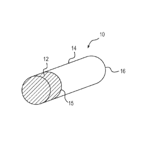
Referring to Fig. 4, a first embodiment of a wave emitter 10 will be
described. The wave emitter 10 has a waveguide 14 and a single transducer 12
disposed at a first end 15 of the waveguide 14. A second end 16 of the
waveguide 14
is free. When in operation, the second 16 is put into contact with a medium
104 in
10 which the
wave emitter 10 emits mechanical waves. The medium 104 and a method
for generating mechanical waves will be described below.
[00101] The
transducer 12 is fixedly disposed to the first end 15 by two screws
(not shown) which exert pressure to retain the transducer 12 on the waveguide
14. It is
contemplated that other ways to affix the transducer 12 to the waveguide 14
could be
15 used. For
example, the transducer 12 could be glued to the first end 15 of the
waveguide. It is also contemplated that a gel (similar to the ones used in
ultrasound
imaging) could be disposed between the transducer 12 and the waveguide 14 to
enhance energy transmission between the transducer 12 and the waveguide 14.
The
single transducer 12 is one example of source that could be used to generate
20 mechanical waves into the waveguide 14.
[00102] The
waveguide 14 is an elongated rod of circular cross-section. It is
contemplated that a waveguide 14 could have a cross-section different from
circular.
As shown in Fig. 5, the waveguide 14 could be embodied as a waveguide 14a
having
a C-shape, and as shown in Fig. 6, the waveguide 14 could also be embodied as
a
waveguide 14b being hollow and having a hole 8 along its length. It is also
contemplated that the waveguide 14 could be a combination of the waveguides
14a
and 14b, and could have a C-shape and one or more hole 8 with same or
different
shape and sizes. It is also contemplated that the waveguide 14 could have yet
different
shapes of cross-section.
CA 02809746 2013-02-27
WO 2012/025833
PCT/1B2011/002701
21
[00103] The
waveguide 14 has a constant cross-section. It is contemplated that
the waveguide 14 could not have a constant cross-section. For example, the
waveguide 14 could have one end squared and another end circular and could
transition smoothly between the two along its length. In another example, the
waveguide is tapered.
[00104] The
waveguide 14 has an aspect ratio of 40. It is contemplated that the
aspect ratio of the waveguide 14 could range between 10 and 1000. A length of
the
waveguide 14 is 1000 mm, and a cross-section area is 25 mm (area: 490 mm2).
The
length of the waveguide 14 is preferably chosen, on one end to accommodate the
fact
that the longer the waveguide 14, the more dispersed a mechanical wave will be
(and
therefore the higher the gain) and on the other end, to accommodate the fact
that the
longer the waveguide 14, the more attenuated the mechanical wave will be after
propagation through the waveguide 14. It is contemplated that the waveguide 14
could
have other dimensions. For example, the length of the waveguide 14 could be
between
200 mm and 1500 mm, and the diameter could be between 1 mm and 50 mm.
[00105] The
waveguide 14 is straight and inflexible. It is contemplated that the
waveguide 14 could have some curvature. For example, a radius of curvature of
the
waveguide 14 could be one order of magnitude greater than a wavelength of a
signal
propagating through waveguide 14. As shown in Fig. 7, the waveguide 14 could
be
embodied as a waveguide 14C that is flexible. The flexible waveguide 14C could
have a size and mechanical compliance adapted to allow insertion of the
waveguide
14C in place where access is restricted.
[00106] The
waveguide 14 is made of aluminum 6061-T6. It is contemplated
that the waveguide 14 could be made of a different type of aluminum or a
different
material. It is also contemplated that the waveguide 14 could be made of an
alloy of
materials. For example the waveguide 14 could be made of aluminum, magnesium,
stainless steel, titanium, etc. It is also contemplated that the waveguide 14
could be
formed of two or more adjacently arranged waveguides. For example the
waveguide
14 could be made of two concentrically arranged waveguides, each waveguide
being
made of a different material. The waveguide 14 is dispersive within a
bandwidth of
the transducer 12. The waveguide 14 also has a low attenuation coefficient
around the
central frequency of the transducer 12 for maximizing amplification gain.
CA 02809746 2013-02-27
WO 2012/025833
PCT/1B2011/002701
22
[00107] The
transducer 12 is a single gas matrix piezoelectric of The Ultran
Group model GWC-D28-10. The transducer 12 has a diameter of 25 mm and is sized
to cover an entirety of the first end 15 of the waveguide 14. It is
contemplated that the
transducer 12 could be bigger or smaller than the first end 15. When the
transducer 12
is of the size or bigger than the cross-section of the waveguide 14, a planar
wave can
be generated. When the transducer 12 is smaller than the cross-section of the
waveguide 14 multiple reflections at walls of the waveguide 14 may deform the
planar wave as it travels the waveguide 14. The planar waves are generally
unfocused
and excite one or more longitudinal modes of the waveguide 14. It is
contemplated
that the mechanical waves could not be planar, could not be unfocused, and
could
excite modes other than longitudinal modes.
[00108] The
transducer 12 is disposed at the first end 15 perpendicularly to a
longitudinal direction of the waveguide 14. It is contemplated that the
transducer 12
could be positioned at the first end 15 not perpendicularly to the
longitudinal direction
of the waveguide 14. It is contemplated that some reverberations could occur
when
the transducer 12 is not disposed perpendicularly to the longitudinal
direction of the
waveguide 14.
[00109] The
transducer 12 has a central frequency of 600 kHz. It is
contemplated that the transducer 12 could have a central frequency different
from 600
kHz. The transducer's 12 central frequency is preferably chosen in accordance
with
the dispersive properties of the waveguide 14. In the present case, a central
frequency
of 600 kHz is desired because the waveguide 14 is made of aluminum and is
dispersive within a range around 600 kHz for the dimensions of the waveguide
14
recited above. A bandwidth of the transducer 12 is from 300 kHz to 900 KHz. It
is
contemplated that the transducer 12 could have a different bandwidth.
[00110]
Referring now to Fig. 8, a second embodiment of a wave emitter 20
will now be described. The wave emitter 20 is similar to the wave emitter 10
but
features a bi-directional transducer 22 in place of the unidirectional
transducer 12.
Elements of the wave emitter 20 common to the wave emitter 10 will have same
reference numerals, and will not be described in detail herein again.
CA 02809746 2013-02-27
WO 2012/025833
PCT/1B2011/002701
23
[00 1 1 1] The bi-
directional transducer 22 can convert electric signals into
mechanical waves and reversely, mechanical waves into electrical signals. The
bi-
directional transducer 22 enables the wave emitter 20 to detect mechanical
waves in a
medium 104 (shown in Fig. 11) in addition to emitting mechanical waves in the
.. medium 104. It is contemplated that a transducer assembly could replace the
bi-
directional transducer 22. The transducer assembly could be formed by the
association
of two transducers, the assembly covering the first end 15 of the waveguide
14. The
two transducers could be disposed adjacent to each other or concentrically
arranged.
One of the two transducers could be used to emit mechanical waves, and the
other to
receive mechanical waves.
[00112] An
acoustic impedance coupler 18 (shown in Fig. 9) can be coupled to
any of the wave emitters 10 and 20 for increasing energy transmission of the
mechanical wave between the second end 16 of the waveguide 14, and the medium
104. The acoustic impedance coupler 18 includes a layer of glass and a layer
of epoxy
between the glass and the second end 16 of the waveguide 14. The epoxy is used
to
glue the glass to the waveguide 14. Each of the layers of epoxy and glass is
disk
shaped to match the circular cross-section of the waveguide 14. The layer of
epoxy
has a thickness of 730 gm, and the layer of glass has a thickness of 300 gm.
The
acoustic impedance coupler 18 has an acoustic impedance intermediate to an
acoustic
impedance of the waveguide 14 and to an acoustic impedance of the medium 104.
It is
contemplated that the acoustic impedance coupler 18 could be embodied as a
structure
having different shape or material, or be even a gel or a softer material. It
is also
contemplated that the acoustic impedance coupler 18 could include a plurality
of
layers of glass and epoxy.
[00113] An acoustic lens 23 (shown in Fig. 10) can be disposed at the
second
end 16 of the waveguide 14 of any of the wave emitters 10 and 20, to
geometrically
focus the mechanical waves emitted into the medium 104. It is also
contemplated that
the wave emitters 10 and 20 could have the acoustic lens 23 and the acoustic
impedance coupler 18 disposed is series at the second end 16 of the waveguide
14. It
is also contemplated that the acoustic lens 23 could not be used for focusing
the
mechanical waves emitted into the medium 104. For example, the wave emitters
10
and 20 could exploit diffraction effects at the second end 16 of the waveguide
14 to
CA 02809746 2013-02-27
WO 2012/025833
PCT/1B2011/002701
24
focus energy at a predetermined spatial location within the medium 104.
Diffraction
patterns arc dependent on the shape and size of the second end as well as on a
wavelength of the desired output wave. In other example, the second end 16 of
the
waveguide 14 could be shaped so as to geometrically focus the mechanical
waves.
[00114] Referring to Fig. 11, a wave generator 100 will now be described.
The
wave generator 100 is a system powering the wave emitter 10 and used to
program the
wave emitter 10 to generate desired mechanical waves.
[00115] The wave
emitter 10 is powered by a signal generator 114, which is
programmable by a computer 106. The signal generator 114 is a National
Instruments,
PXI 5412 (14-Bit 100 MS/s). The computer 106 is a general purpose computer
well
known in the art. It is contemplated that the computer 106 could be another
type of
computing interface. It is contemplated that the signal generator 114 could be
different. The computer 106 has a processor 107 in communication (data 108)
with a
machine-readable storage medium 110. The machine-readable storage medium 110
is
used to store the data 108, which are digitized input signals corresponding to
mechanical input waves 128. The computer 106 constitutes an interface used by
a user
to program an input signal 112 that will lead to the generation of one or more
mechanical input waves 128.
[00116] The
signal generator 114 transforms the input signal 112 into a low
voltage signal 116. The low voltage signal 116 is transformed into a higher
voltage
signal 120 by an amplifier 118. The amplifier 118 is a RITEC, GA-2500A (400
Watts). It is contemplated that the amplifier 118 could be different. The
higher voltage
signal 120 goes through a coupler 122 which optimizes power transfer between
the
amplifier 118 and the wave emitter 10 by coupling electric impedances of the
amplifier 118 and the wave emitter 10. It is contemplated that the amplifier
118 could
be omitted. After passage through the coupler 122, the higher voltage signal
120
becomes input voltage signal 124 to the wave emitter 10. It is contemplated
that the
coupler 122 could be omitted.
[00117] The
transducer 12 converts the input voltage signal 124 into the
mechanical input wave 128, and the waveguide 14 propagates the mechanical
input
wave 128 towards the second end 16 of the waveguide 14 which is being put in
CA 02809746 2013-02-27
WO 2012/025833
PCT/1B2011/002701
contact with the medium 104 for generating mechanical waves 102 in the medium
104. The medium 104 is degassed tap water at room temperature. It is
contemplated
that the medium 104 could be different. The waveguide 14 being dispersive, the
mechanical input wave 128 is distorted into a mechanical output wave 102 by
the time
5 the mechanical input wave 128 has reached the second end 16. Some component
waves of the mechanical input wave 128 travel faster than others and can reach
the
second end 16 at the same time as the slower component waves. When the slower
and
faster components waves reach simultaneously the second end 16 an interaction
occurs to form the mechanical output wave 102. The mechanical output wave 102
is a
10 recombination of the mechanical input wave 128. At the second end 16
of the
waveguide 14, the mechanical output wave 102 is emitted into the medium 104.
[00118] To use
the wave generator 100, the user starts with determining the
desired mechanical output wave 102 that he/she wishes to emit in the medium
104.
The user uses the computer 106 to determine the input signal 112 input to the
signal
15 generator 114 that ultimately will lead to the mechanical output
wave 102 after
conversion by the transducer 12 and propagation through the dispersive
waveguide
14. A method for generating the mechanical output waves 102 will be described
below.
[00119] The
input signal 112 is calculated taking into consideration the
20
dispersive properties of the waveguide 14 and in some cases taking into
consideration
the physical properties of the medium 104. The dispersive properties of the
waveguide
14 and the physical properties of the medium 104 are determined in a prior
calibration
step typically done only once. The waveguide 14 is calibrated using the
impulse
response method. It is contemplated that other methods well known in the art
could be
25 used to calibrate the waveguide 14. For example, time reversal
mirror, inverse filter,
or analytical calculation of dispersion curves could be used. In the impulse
response
method, a known pulse is sent by the transducer 12 into the waveguide 14, and
after
traveling through the waveguide 14 and being deformed due to the dispersive
properties of the waveguide 14, the pulse propagates in the medium 104 until
reaching
a hydrophone (not shown) priory placed in front of the waveguide 14. An
advantage
of the impulse response calibration method is that it allows to take into
consideration
the characteristics of the medium 104 itself. It is possible that the choice
of medium
CA 02809746 2013-02-27
WO 2012/025833
PCT/1B2011/002701
26
104 influences a shape of the mechanical output waves 102, after having been
generated at the second end 16, when the mechanical output waves 102 enter the
medium 104. Therefore, it is preferable that the calibration takes into
consideration
the medium 104. It is contemplated that the medium 104 could be calibration in
a
separate calibration step. It is also contemplated that the physical
properties of the
medium 104 could not be calibrated. The hydrophone is a Milller-Platte
Needleprobe
100-100-1 with a sensitive diameter inferior to 0.5 mm. It is contemplated
that the
hydrophone could be different. The hydrophone records the emitted wave which
is
used along with the impulse to characterize a frequency response function of
the wave
emitter 10. The frequency response function is a key of the system (wave
emitter 10)
which once known allows to determine how any wave will be modified into, after
propagation in the dispersive waveguide 14. It is contemplated that if the
transducer
12 were bi-directional, it could be possible to use, instead of the
hydrophone, a
reflection of the impulse itself at the second end 16 of the waveguide 14 in
order to
determine the frequency response function of the wave emitter 10.
[00120] Referring now to Fig. 12, a wave generator 200 will now be
described.
The wave generator 200 is a system powering the wave emitter 20 used to
generate
the desired mechanical output waves 102 and further to record information
coming
from the medium 104 for the purpose of, for example, locating a non-
homogeneity in
the medium 104. The wave generator 200 is similar to the wave generator 100,
but
features a diplexer 222 and a digitizer 240. Elements of the wave generator
200
common to the wave generator 100 will have same reference numerals, and will
not
be described herein again.
[00121] The diplexer 222 is located between the amplifier 118 and the
coupler
122. The diplexer 222 acts as a switch to separate electric signals 124
incoming and
outgoing the bi-directional transducer 22. For example, the diplexer 222
separates
signals 234 incoming from the medium 104 through the waveguide 14 from signals
134 incoming from the signal generator 114. The diplexer 222 is only one
example of
a switch. The digitizer 240 transforms a signal 216 outgoing from the diplexer
222
into a signal 212 readable by the computer 106. The bi-directional transducer
22
converts the voltage signal 124 into the corresponding mechanical input wave
128,
CA 02809746 2013-02-27
WO 2012/025833
PCT/1B2011/002701
27
and reversely converts a mechanical wave 228 coming from the waveguide 14
(reverse direction mechanical wave) into a corresponding electric signal 224.
[00122] Emission
of mechanical waves by the wave generator 200 is similar to
the one described below for the wave generator 100, except that the higher
voltage
signal 120 goes through the diplexer 222 and the coupler 122 before entering
the
wave emitter 20 without being noticeably deformed.
[00123]
Reception of mechanical waves by the wave generator 200 starts with
the waveguide 14 receiving a mechanical wave 202 (e.g. perturbation) from the
medium 104 at the second end 16. The mechanical wave 202 could be emitted from
a
source in the medium 104 or reflected by a non-homogeneity in the medium 104.
The
mechanical wave 202 propagates through the waveguide 14 toward the bi-
directional
transducer 22. When the mechanical wave 202 reaches the bi-directional
transducer
22, the mechanical wave 202 has been transformed into the mechanical wave 228
which is a dispersed version of the mechanical wave 202. The bi-directional
transducer 22 converts the mechanical wave 228 into a corresponding electric
signal
224. The electric signal 224 goes through the coupler 122, becomes signal 234,
goes
through the diplexer 222 becomes the signal 216, before reaching the digitizer
240,
and being transformed into the signal 212 readable by the computer 106.
[00124] As
mentioned above, the wave emitter 20 can be used as a location
device for a non-homogeneity. The calibration of the wave emitter 20 can be
done in a
unique calibration step, analytically or experimentally. The calibration of
the wave
emitter 20 is similar to the calibration for the wave emitter 10 described
above. A
method for locating a non-homogeneity in the medium 104 starts with the wave
emitter 200 emitting a pulse. Then, the pulse is reflected by the non-
homogeneity and
reaches back the wave emitter 20 (with some distortion due to propagation in
the
medium 104). Dispersion in the waveguide 14 is taken into consideration by the
prior
calibration of the wave emitter 20. The reflected mechanical wave from the non-
homogeneity is compared with the original pulse sent toward the non-
homogeneity to
determine a distance between the second end 16 of the waveguide 14 and the non-
homogeneity. Comparison can be performed by the computer 106. It is also
possible
to exploit the waves reflected by the non-homogeneity to characterize
heterogeneities
in the medium 104.
CA 02809746 2013-02-27
WO 2012/025833
PCT/1B2011/002701
28
[00125]
Referring now to Fig. 13, a method 300 for generating a desired
mechanical wave by exploiting waveguide dispersion of the wave emitter 10 in
the
wave generator 100 will now be described. The method 300 will be described
assuming the wave emitter 10 has been priory calibrated and the dispersive
properties
of the waveguide 14 (and optionally the physical properties of the medium 104)
are
known, as described above. It is contemplated that the method 300 could be
used for
generating a desired mechanical wave by exploiting waveguide dispersion of the
wave
emitter 20 in the wave generator 200.
[00126] The
method 300 starts at step 302, with the user determining the
desired mechanical output wave 102. As described above, the desired mechanical
output wave 102 has at least two component waves having relative phases
between
them. Each component wave has (among other characteristics) an associated
frequency and an associated mode within the predetermined range of frequencies
and
modes for which the waveguide 14 is dispersive.
[00127] At step 304, the input signal 112 is calculated by the computer
106.
The input signal 112 corresponds to the mechanical input wave 128 produced by
the
transducer 12, which once distorted by the dispersive waveguide 14 will
recombine
into the desired mechanical output wave 102. As mentioned above, the input
signal
112 is calculated taking into account the dispersive relations of the
waveguide 14, so
as to compensate at the end 16 of the waveguide 14 for the relative phase
shifts
introduced by the waveguide 14 as the components waves of the mechanical input
wave 128 travel through it.
[00128] From
step 304 the method 300 can go either through step 305, or
directly to step 306. At step 305, the input signal 112 is amplified. One way
to
amplify the input signal 112 is to saturate it before amplifying it. To do so,
a
magnitude of the input signal 112 for the different frequencies composing it,
is fixed
to a limit value, and consequently amplified. Saturating and amplifying the
input
signal 112 allows to amplify without affecting relative phases. It is
contemplated that
one could amplify and then saturate the input signal 112. It is contemplated
that the
saturation and amplification could be done differently. An example of
amplification
by saturation is given below.
CA 02809746 2013-02-27
WO 2012/025833
PCT/1B2011/002701
29
[00129] At step
306, the input signal 112 is transformed by the transducer 12
into the mechanical input wave 128. The mechanical input wave 128 travels
through
the waveguide 14 and gets distorted due to the dispersive properties of the
waveguide
14.
[00130] A step 310, the desired mechanical output wave 102 is generated
from
a recombination of the mechanical input wave 128 at the second end 16. Once
the
desired mechanical output wave 102 is generated, it is emitted into the medium
104 at
step 310. If at step 312, the wave emitter 10 is coupled to the acoustic
impedance
coupler 18, the desired mechanical output wave 102 propagates through the
acoustic
impedance coupler 18 before reaching the medium 104. If at step 314 the wave
emitter 10 is coupled to the acoustic lens 23, the desired mechanical output
wave 102
propagates through the acoustics lens 23 before reaching the medium 104 at
step 314.
The wave emitter 10 could also be coupled to the acoustic lens 23 and the
acoustic
impedance coupler 18.
[00131] Turning now to Figs. 14 to 17, an example of mechanical input wave
128 and a resulting desired mechanical output wave 102 will be described. In
the
experiment leading to the results shown in Figs. 14 to 17, the wave emitter 10
is
connected to the impedance acoustic coupler 18 but has no acoustic lens 23
attached
to it. As mentioned earlier, the medium 104 is degassed tap water at room
temperature. The wave emitter 10 is positioned so as to have the second end 16
in
contact with the medium 104. In this experiment, the user desires to emit a
pulse of a
normalized amplitude of 3 and a desired time signature of 1.67 p s. It is
contemplated
that the experiment could be performed for generating a pulse other than the
one
above. It is also contemplated that the experiment could be performed for
generating
mechanical waves other than a pulse. The user uses the computer 106 to
determine a
mechanical input wave 400 that needs to be generated by the transducer 12 in
order to
generate at the second end 16 of the waveguide 14, the desired pulse. Fig. 14
shows
the mechanical input wave 400 as generated by the transducer 12. As can be
noticed,
the wave 400 is characterized by a time signature of 0.2 ms and an amplitude
of 1
(Fig. 14 showing the amplitude normalized). As shown in Fig. 15, a pulse 410
characterized by a time signature of approximately 1.67 las and an amplitude
of 3
(Fig. 15 showing the amplitude normalized) is recorded at the second end 16 of
the
CA 02809746 2013-02-27
WO 2012/025833
PCT/1B2011/002701
waveguide 14. It can be seen that, the wave generator 10 has passively
compressed in
time and has amplified the wave 400 to form the pulse 410. The gain is 3 and
the
temporal compression is of a factor of 120. As mentioned above, the user can
also
saturate the signal leading to the generation of the mechanical input wave
400, so as
5 to amplify
even further the amplitude of the desired pulse 410. As shown in Fig. 16,
when recorded at the second end 16 of the waveguide 14 is a pulse 420 having
the
same time signature as the pulse 410, but having an amplitude of 8 (Fig. 16
showing
the amplitude normalized). Saturation did not affect the time signature, and
has
increased the amplitude by about 2.7 times compared to the same experiment
without
10 saturation.
With saturation the overall gain of this experiment is 8. Once the pulses
410 and 420 are emitted in the medium 104, non-linear effects of the medium
104
distort the pulses 401, 402 as they travel through it. As shown in Fig. 17 for
the pulse
410, at 70 mm along a longitudinal axis of the waveguide 14, the pulse 410 has
becomes a shockwave 430. The shockwave 430 is characterized by a time
signature of
15 less than 1
las and an amplitude of 100 bars. This amplitude of the shockwave 430 is
20 times more than a wave that would be created by the same transducer 12
(without
waveguide 14), driven by the same electrical power and emitting in the same
medium
104 (water).
[00132]
Modifications and improvements to the above-described embodiments
20 of the
present invention may become apparent to those skilled in the art. The
foregoing description is intended to be exemplary rather than limiting. The
scope of
the present invention is therefore intended to be limited solely by the scope
of the
appended claims.