Note: Descriptions are shown in the official language in which they were submitted.
CA 02809798 2017-01-31
73766-130
- 1 -
SYSTEMS AND METHODS FOR TOMOGRAPH1C IMAGING IN DIFFUSE MEDIA
USING A HYBRID INVERSION TECHNIQUE
=
[0001]
Field of The Invention
[0002] The invention relates generally to in vivo imaging systems and methods.
More
particularly, in certain embodiments, the invention relates to systems and
methods for
tomographic imaging employing a fast reconstruction technique.
Background of the invention
[0003] The amount of data used in optical tomography image reconstruction has
increased by
several orders of magnitude in recent years. This is primarily due to the use
of large detector
arrays. e.gõ on the order of la' elements or higher. When coupled with a large
number of
sources. e.gõ on the Order of la= sources (such large number being
facilitated, for example, by
the use of non-contact measurements) large data sets easily in the range of I
05 source-detector
pairs are generated. These large data sets reduce the ill-posed nature of the
inversion, but also
present an inherently large computational burden for reconstruction of
tomographic images.
Using traditional real-space weight matrix and Algebraic Reconstruction
Techniques (ART) for
the inversion yields impractically long computational times, in some instances
longer that 24
hours. Similarly, using matrix-related inversion methods such as Singular
Value
Decomposition is not viable due to the amount of memory required. Thus, there
is a need for a
different approach that can handle large data sets and still maintain
reasonably low
computational times,
[0004] A powerful formalism for significantly reducing the number of
measurements while
maintaining the same amount of useful information is to work in Fourier Space,
Diffuse light
in the continuous wave (CW) regime is known to present only low spatial
frequency =
contributions.. By using all real-space data while selecting only a few low-
frequency
CA 02809798 2013-02-27
WO 2011/025950 PCT/US2010/046973
- 2 -
components in Fourier space, it is possible to benefit from the same amount of
useful
information while retaining a lower number of measurements.
[0005] Certain limited Fourier space techniques have been used to solve
inverse problems in
the past, for example, backprojection techniques and direct inversion
techniques.
[0006] Backprojection suffers from being non-quantitative, low in resolution
and incapable
of good depth-discrimination [Matson, C. L., N. Clark, et al. (1997). "Three-
dimensional tumor
localization in thick tissue with the use of diffuse photon-density waves."
Applied Optics 36:
214-220; Matson, C. L. (2002). "Diffraction Tomography for Turbid Media."
Advances in
Imaging and Electron Physics 124: 253-342; Li, X. D., T. Durduran, et al.
(1997). "Diffraction
tomography for biochemical imaging with diffuse-photon density waves." Optics
Letters 22:
573-575; Li, X., D. N. Pattanayak, et al. (2000). "Near-field diffraction
tomography with
diffuse photon density waves." Phys Rev E 61(4 Pt B): 4295-309].
[0007] Complete Fourier approaches, also termed Direct Inversion, present
severe
reconstruction artifacts and generally are not applicable to datasets with
fewer than 0(101)
source positions [(Schotland, J. C. and V. A. Markel (2001). "Inverse
scattering with diffusing
waves." J Opt Soc Am A Opt Image Sci Vis 18(11): 2767-77.; Markel, V. A. and
J. C.
Schotland (2001). "Inverse problem in optical diffusion tomography. I. Fourier-
Laplace
inversion formulas." J Opt Soc Am A Opt Image Sci Vis 18(6): 1336-47.; Markel,
V. A. and J.
C. Schotland (2004). "Symmetries, inversion formulas, and image reconstruction
for optical
tomography." Phys Rev E Stat Nonlin Soft Matter Phys 70(5 Pt 2): 056616.;
Markel, V. A. and
J. C. Schotland (2001). "Inverse scattering for the diffusion equation with
general boundary
conditions." Phys Rev E 64(3 Pt 2): 035601].
Summary of the Invention
[0008] The invention presents a hybrid approach for fast reconstruction of
tomographic
images that offers advantages over backprojection and direct inversion
techniques. In this
hybrid approach, one or more subsets of large tomographic datasets are
selected in frequency
space (e.g.. Fourier space) while one or more subsets are maintained in real
space, then the
weight matrix is inverted to obtain the tomographic representation of a region
of interest within
the subject in real space. This achieves fast computational times while
maintaining good
tomographic reconstruction performance.
CA 02809798 2013-02-27
WO 2011/025950 PCT/US2010/046973
- 3 -
[0009] For example, in preferred embodiments, the detector data is Fourier-
transformed,
while the sources and reconstructions are maintained in real-space. This
enables the use of
very large detector sets while still using lower numbers of sources (e.g.,
less than 102) than the
complete Fourier (direct inversion) approaches, and does not present the
typical Fourier
artifacts in the reconstruction because data is reconstructed in real space.
This additionally
enables full body imaging and the imaging of larger anatomies, since the total
number of
measurements in Fourier Space is very low but still represents the full body
being imaged. Fast
computation in larger scan fields is made possible, with both satisfactory
spatial resolution and
computation speed, allowing fluorescence molecular tomographic imaging of not
only mice
and rats, but also larger animals such as guinea pigs, rabbits, non-human
primates, other
mammals, and humans.
[0010] The invention provides systems and methods for transforming and
selecting specific
constituents of very large tomographic datasets for the purpose of
reconstructing three-
dimensional quantitative distributions of signal. These methods yield a faster
yet still accurate
depiction of the localization and distribution of the signal in the
object/subject, including
quantification and distribution of signals, reporters and/or agents (i.e.,
contrast agents or
probes) in such objects/subjects than can be achieved by conventional
tomographic
reconstruction techniques.
[0011] In accordance with certain embodiments of the present invention, fast
tomographic
reconstruction methods and algorithms are described herein. The methods and
algorithms have
been fully parameterized to accommodate different imaging settings optimized
for a variety of
target objects/subjects and regions and a variety of different agents or
probes. In particular, it is
an object of the invention to provide such algorithms and corrected image
analysis methods for
use in biological research, as well as in preclinical and/or clinical
settings. In particular, the
present invention provides corrected imaging algorithms that can optionally be
used with one
or more imaging agent or probes for in vivo molecular imaging.
[0012] In one aspect, the invention provides a fluorescent molecular
tomography system
comprising: an excitation source; an optical imaging apparatus configured to
direct light from
the excitation light source into a subject at a plurality of locations; a
detector configured to
detect at multiple locations light emanating from a region of the subject; and
a processor
configured to process data corresponding to the detected light emanating from
the region of the
subject to produce a tomographic representation of the region of the subject,
wherein the
processor is configured to execute instructions to: (a) establish a forward
model of excitation
CA 02809798 2013-02-27
WO 2011/025950 PCT/US2010/046973
- 4 -
light propagation from the region to the detector using the data corresponding
to the detected
fluorescent light, wherein: (i) the excitation light source is represented in
real space; (ii) the
detected fluorescent light is represented in frequency space; and (iii) the
forward model is
established as a discretized weight matrix of normalized elements; and (b)
invert the weight
matrix to obtain the tomographic representation of the region of the subject
in real space.
[0013] In certain embodiments, the detector is further configured to detect at
multiple
locations excitation light emanating from the subject, and wherein the
processor is configured
to execute instructions to establish the forward model using the data
corresponding to the
detected excitation light and the detected fluorescent light wherein the
detected excitation light
and the detected fluorescent light are represented in frequency space.
[0014] In certain embodiments, in the forward model, a surface of the subject
is identified
and boundary conditions are established for the surface. In addition, in the
forward model,
boundary removal equations can be used to convert data corresponding to the
surface into a
simulated infinite homogeneous medium, thereby simplifying the forward problem
(see for
example, Ripoll and Ntziachristos, "From Finite to Infinite Volumes: Removal
of Boundaries
in Diffuse Wave Imaging", Physical Review Letters 96,173903, 2006). In certain
embodiments, the data corresponding to the surface of the subject comprises an
experimental
measurement of surface flux distribution.
[0015] In certain embodiments, the detected fluorescent light is emitted from
a probe within
the region of the subject, and the forward model in (a) models excitation
light propagation from
the excitation light source to the probe and emitted fluorescent light
propagation from the probe
to the detector. In addition, in the forward model, a Born approximation is
used to express an
intensity of the detected fluorescent light emitted from the probe having
spatially-varying
concentration within the region. In certain embodiments, the intensity of the
detected
fluorescent light is normalized using an intensity of the spatially-
corresponding detected
excitation light. In addition, the forward model in (a) represents the
detected excitation light
and the detected fluorescent light in Fourier space.
[0016] In certain embodiments, the excitation light source or the optical
imaging apparatus
comprises a scanner configured to direct light into the subject at a plurality
of locations, thereby
defining a plurality of source locations. In certain embodiments, the
plurality of source
locations are non-uniformly spaced. In certain embodiments, the detector
comprises an array
of detector locations, and wherein the forward model is established using data
obtained from
= 81703269
- 5 -
the array of detector locations. In certain embodiments, there are
substantially more detector
locations than source locations.
[0017] In certain embodiments, the optical imaging apparatus
comprises a chamber. In
certain embodiments, the chamber is an animal chamber.
[0018] In certain embodiments, the subject is a human. In certain
embodiments, the
subject is a guinea pig, rabbit, non-human primate, or other mammal. In
certain embodiments, the
subject is a mouse, rat, amphibian, fish, or bird. The subject may be a
vertebrate animal, for
example, a mammal, including a human.
[0019] In certain embodiments, the excitation light is near-infrared
light. In addition, the
excitation light has a wavelength within a range from about 500 nanometers to
about 1000
nanometers. In certain embodiments, the excitation light has a wavelength
within a range from
about 635 nanometers to about 850 nanometers.
[0020] In certain embodiments, the excitation light is continuous
wave (CW) light. The
excitation light comprises at least one member selected from the group
consisting of continuous
wave light, time-resolved light, and intensity modulated light.
[0021] In certain embodiments, the forward model models excitation
light propagation
from the excitation light source to the region of the subject and fluorescent
light propagation from
the region to the detector, where there is free space between the surface of
the subject and the
detector.
[0022] In another aspect, the present invention provides a method of
imaging a
distribution of a fluorescent probe within a region of a subject, the method
comprising the steps:
(a) administering to the subject a probe comprising a near-infrared
fluorophore; (b) directing near-
infrared excitation light into the subject at multiple locations to
transilluminate through or reflect
from the region of the subject; (c) detecting fluorescent light emitted from
the probe within the
region of the subject; and (d) processing, by a processor of a computing
device, data
corresponding to the detected fluorescent light to provide a tomographic
representation of the
region of the subject, the tomographic representation comprising a map of
concentration of the
probe within the region of the subject, wherein the processing step comprises:
(i) establishing a
forward model of excitation light propagation from an excitation light source
to the probe within
the region of the subject and of emission light propagation from the probe to
a detector using the
data corresponding to the detected fluorescent light wherein: (A) the
excitation light source is
CA 2809798 2017-12-07
= 81703269
- 6 -
represented in real space; (B) the detected fluorescent light is represented
in frequency space; and
(C) the forward model is established as a discretized weight matrix of
normalized elements; and
(ii) inverting the weight matrix to obtain the tomographic representation of
the region of the
subject in real space.
100231 In certain embodiments, the step (c) comprises detecting excitation
light
transmitted through or reflected from the region of the subject, and wherein
step (e) comprises
processing data corresponding to the detected fluorescent light and the
detected excitation light,
wherein the processing step comprises establishing the forward model using the
data
corresponding to the detected fluorescent light and the detected excitation
light, wherein the
detected fluorescent light and the detected excitation light are represented
in frequency space.
[0024] In another aspect, the present invention provides a method
for imaging using a
hybrid inversion technique to image the distribution of a fluorescence within
a region of a subject,
including but not limited to endogenous fluorescence, bioluminescence or
fluorescent proteins, the
method comprising: (a) directing excitation light into the subject at multiple
locations to
transilluminate through or reflect from at least a portion of the region of
the subject containing the
fluorescence; (b) optionally detecting excitation light transmitted through or
reflected from the
region of the subject; (c) detecting fluorescent light emitted from within the
subject; and (d)
processing data corresponding to the detected fluorescent light and the
optionally detected
excitation light to provide a tomographic representation of the region of the
subject, wherein the
processing step comprises (i) establishing a forward model of excitation light
propagation from an
excitation light source to the light source within the subject and of emission
light propagation
from the light source of the subject to a detector using the data
corresponding to the optionally
detected excitation light and the detected fluorescent light, wherein: (A) a
surface of the subject is
identified and boundary conditions are established for the surface, or,
alternatively, boundary
removal equations are used to convert data corresponding to the surface of the
subject into a
simulated infinite homogeneous medium, thereby simplifying the forward
problem; (B) the
excitation light source is represented in real space; (C) the detected
fluorescent light and the
optionally detected excitation light are represented in frequency space; and
(D) the forward model
is established as a discretized weight matrix of normalized
CA 2809798 2017-12-07
CA 02809798 2013-02-27
WO 2011/025950 PCT/US2010/046973
- 7 -
elements; and (ii) inverting the weight matrix to obtain the tomographic
representation of the
region of the subject in real space.
[0025] In certain embodiments, the tomographic representation comprises a map
of
concentration of the probe within the region of the subject.
[0026] In addition, tomographic representation indicates an area of disease
within a region of
the subject. Furthermore, the tomographic representation can indicate an area
of inflammation,
arthritis, cancer, metastasis, plaque, infectious disease, cardiovascular
disease, respiratory
disease, metabolic disease, central nervous system disease, immune disease,
neurodegenerative
disease, dermatological disease, ophthalmic disease, cutaneous disease or a
combination of two
or more of the foregoing, within the region of the subject. In certain
embodiments, the
tomographic representation indicates a boundary of a disease site, such as a
tumor within the
region of the subject.
[0027] In certain embodiments, the probe used for imaging is an endogenous
probe. In
certain embodiments, the probe may be exogenous and administered to the
subject.
[0028] In certain embodiments, the probe comprises a member selected from the
group
consisting of a molecular probe, a fluorescent molecular probe, a phototherapy
based
fluorescent probe, an activatable fluorescent probe, an enzyme-activatable
fluorescent probe, an
activity based probe, a targeted fluorescent probe, a near-infrared
fluorescent molecular probe,
a fluorescent protein, a fluorescent biomolecule, a non-specific fluorescent
probe, quantum
dots, a receptor-targeted near-infrared fluorochrome, an antibody-or antibody-
like targeted
near-infrared fluorochrome, a wavelength-shifting beacon, a multi-color
fluorescence probe,
and a lanthanide metal-ligand probe. In addition, the probe may comprise a
fluorochrome
attached to a delivery vehicle comprising any one or more of a polymer, a
dendrimer, a protein,
a carbohydrate, a lipid sphere, and a nanoparticle.
[0029] In certain embodiments, the method of imaging comprises administering
to the
subject a plurality of probes having optically distinguishable fluorescent
emission wavelengths,
detecting fluorescent light emitted from each of the probes, and processing
data corresponding
to the detected light to provide one or more tomographic representations. In
addition, the effect
of the probe on the region within the object may be determined using the
tomographic
representation. Furthermore, the method may comprise imaging at excitation and
emission
wavelengths of a natural tissue chromophore.
CA 02809798 2013-02-27
WO 2011/025950 PCT/US2010/046973
- 8 -
[0030] In certain embodiments, imaging steps (b), (c), (d). and (e) may be
repeated to obtain
tomographic representations as a function of time. In addition, the kinetics
of a distribution of
the probe within the region can be monitored using tomographic
representations. The kinetics
of activation of the probe can be monitored using tomographic representations.
[0031] In certain embodiments, the method may comprise imaging at excitation
and emission
wavelengths of a natural tissue chromophore.
[0032] In certain embodiments, the tomographic representation comprises a map
showing
quantity of the probe in three dimensions. The tomographic representation may
comprise one
or more images, and wherein the method further comprises storing the one or
more images,
1() displaying the one or more images, or both storing and displaying the
one or more images. In
addition, the tomographic representation comprises a three-dimensional
tomographic image and
the method further comprises the step of combining the three-dimensional
tomographic image
with photographic, pictorial, magnetic resonance, x-ray computed tomography,
ultrasound,
single photon emission tomography, or positron-emission tomography imaging
data. and
representations.
[0033] In certain embodiments, the imaging method further comprises the step
of detecting
or monitoring a cellular abnormality or disease using tomographic
representation. The cellular
abnormality or disease can comprise at least one member selected from the
group consisting of
cancer, oncological disease, infectious disease, metabolic disease,
respiratory disease,
cardiovascular disease, AIDS, immune disease, central nervous system disease,
neurodegenerative disease, inflammation, dermatological disease, ophthalmic
disease,
cutaneous disease, inherited diseases, environmental diseases, bone-related
diseases,
immunologic disease, and surgery-related complications.
[0034] In certain embodiments, the subject of the imaging method is a mammal.
In certain
embodiments, the subject is a human. In certain embodiments, the subject is a
guinea pig,
rabbit, non-human primate, or other mammal. In certain embodiments, the
subject is a mouse,
rat, amphibian, fish, or bird. The subject may be a vertebrate animal, for
example, a mammal,
including a human.
[0035] In certain embodiments, the probe of the imaging method may comprise an
endogenous fluorophore that is encoded by a gene within the subject. The
expression of the
gene encoding the fluorophore can be determined using tomographic
representation. The
endogenous fluorophore can be a fluorescent protein or biomolecule, including
but not limited
to green, red and infrared fluorescent proteins.
CA 02809798 2017-01-31
=
73766-130
- 9 -
[0036] In another aspect, the invention is an apparatus for
reconstructing a
tomographic representation of a probe within a region of a subject, the
apparatus comprising:
a memory that stores code defining a set of instructions; and a processor that
executes the
instructions thereby to: (a) establish a forward model of excitation light
propagation from an
excitation light source to the probe within the region of the subject and of
emission light
propagation from the probe to a detector using data corresponding to detected
fluorescent
light, wherein: (i) the excitation light source is represented in real space;
(ii) the detected
fluorescent light is represented in frequency space; and (iii) the forward
model is established
as a discretized weight matrix of normalized elements; and (b) invert the
weight matrix to
obtain the tomographic representation of the region of the subject in real
space.
[00371 In certain embodiments, the processor executes the instructions
to establish the
forward model using data corresponding to detected excitation light and the
detected
fluorescent light, wherein the detected fluorescent light and the detected
excitation light are
represented in frequency space.
[0038] In another aspect, the invention provides a diffuse optical
tomography system
comprising one or more illumination sources; an optical imaging apparatus
configured to
direct light from the at least one illumination source into a subject at a
plurality of locations; a
detector configured to detect at multiple locations light emanating from the
subject to obtain a
first and second measurement, wherein the first measurement is a reference
measurement and
the second measurement corresponds to absorption of at least a portion of the
illuminating
light as it passes through a light-absorbing region within the subject, and
wherein the
reference measurement does not reflect all of said absorption; and a processor
configured to
process data corresponding to the first and second measurements of detected
light emanating
from the subject, wherein the processor is configured to execute instructions
to: (a) establish a
forward model of light propagation from at least one of the one or more
illumination sources
to the light-absorbing region within the subject and of light propagation from
the region to the
detector using the data corresponding to the first and second measurements,
wherein: (i) the at
least one illumination source is represented in real space; (ii) the detected
light is represented
in frequency space; and (iii) the forward model is established as a
discretized weight matrix of
= 81703269
- 10 -
normalized elements; and (b) invert the weight matrix to obtain a tomographic
representation
of the region of the subject in real space. In addition, the system can
comprise at least two
illumination sources emitting light having different wavelengths. In certain
embodiments, the
at least two illumination sources are near- infrared light sources.
[0039] In certain embodiments, a diffuse optical tomography imaging system
can
comprise at least two illumination sources with different wavelengths
comprising a
wavelength below an isosbestic point of an oxy-hemoglobin (HbO) and a deoxy-
hemoglobin
(Hb), and a wavelength above the isosbestic point.
[0040] Elements of embodiments described with respect to a given
aspect of the
invention may be used in various embodiments of another aspect of the
invention
[0040a] According to one aspect of the present invention, there is
provided a method of
imaging a distribution of a fluorescent probe within a region of a subject,
the method
comprising the steps: (a) administering to the subject a probe comprising a
near-infrared
fluorophore; (b) directing near-infrared excitation light into the subject at
multiple locations to
1 5 transilluminate through or reflect from the region of the subject; (c)
detecting fluorescent light
emitted from the probe within the region of the subject; and (d) processing,
by a processor of
a computing device, data corresponding to the detected fluorescent light to
provide a
tomographic representation of the region of the subject, the tomographic
representation
comprising a map showing quantity of the probe in three dimensions, wherein
the processing
step comprises: (i) establishing a forward model of excitation light
propagation from an
excitation light source to the probe within the region of the subject and of
emission light
propagation from the probe to a detector using the data corresponding to the
detected
fluorescent light wherein: (A) the excitation light source is represented in
real space; (B) the
detected fluorescent light is represented in frequency space; and (C) the
forward model is
established as a discretized weight matrix of normalized elements; and (ii)
inverting the
weight matrix to obtain the tomographic representation of the region of the
subject in real
space.
[0040b] According to another aspect of the present invention, there
is provided a
method of imaging a distribution of a fluorescent probe within a region of a
subjeet, the
method comprising the steps: (a) administering to the subject a probe
comprising a near-
CA 2809798 2017-12-07
'81703269
- 10a -
infrared fluorophore; (b) directing near-infrared excitation light into the
subject at multiple
locations to transilluminate through or reflect from the region of the
subject; (c) detecting
fluorescent light emitted from the probe within the region of the subject; (d)
processing, by a
processor of a computing device, data corresponding to the detected
fluorescent light to
provide a tomographic representation of the region of the subject, the
tomographic
representation comprising one or more images; and (e) storing the one or more
images,
displaying the one or more images, or both storing and displaying the one or
more images,
wherein step (d) comprises: (i) establishing a forward model of excitation
light propagation
from an excitation light source to the probe within the region of the subject
and of emission
light propagation from the probe to a detector using the data corresponding to
the detected
fluorescent light wherein: (A) the excitation light source is represented in
real space; (B) the
detected fluorescent light is represented in frequency space; and (C) the
forward model is
established as a discretized weight matrix of normalized elements; and (ii)
inverting the
weight matrix to obtain the tomographic representation of the region of the
subject in real
space.
[0041] Other features and advantages of the invention will be apparent
from the
following figures, detailed description, and the claims.
[0042] The objects and features of the invention can be better
understood with
reference to the drawings described below, and the claims. In the drawings,
like numerals are
used to indicate like parts throughout the various views.
Brief Description of Drawings
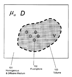
[0043] Figure 1 is a schematic drawing depicting a collection of
fluorophores within a
volume V in an otherwise infinite homogeneous and diffusive medium, in
accordance with an
illustrative embodiment of the invention.
[0044] Figure 2 is a block diagram of the steps of a method for obtaining a
3D map of
an unknown fluorescing or absorbing probe, tissue, or other target object in a
subject,
according to an illustrative embodiment of the invention.
[0045] Figure 3 are images comparatively depicting the real-space
intensity of a point
source and the absolute value of its Fourier transform, according to an
illustrative embodiment
of the invention.
CA 2809798 2017-12-07
=
81703269
- 10b -
[0046] Figure 4 is a graph showing the Fourier- space intensity
profile of a full data
set, with the discretized and cut-off components included in a hybrid
reconstruction of an
illustrative embodiment of the invention displayed as circles.
[0047] Figure 5 is a schematic showing phantom reconstructions
with a cylindrical
fluorescent cavity at several depths, according to an illustrative embodiment
of the invention.
[0048] Figure 6 is a graph illustrating the strong linearity of
quantification in a hybrid
reconstruction according to an illustrative embodiment of the invention.
CA 2809798 2017-12-07
CA 02809798 2013-02-27
WO 2011/025950 PCT/US2010/046973
- 11 -
[0049] Figure 7 is a schematic showing a volume rendering of an in vivo
dataset from a
tumor-bearing mouse injected with a fluorescent contrast agent, according to
an illustrative
embodiment of the invention.
[0050] Figure 8 is a schematic showing comparative volume renderings of
treated and
untreated tumor-bearing animals reconstructed with a hybrid reconstruction
approach,
according to an illustrative embodiment of the invention.
Detailed Description
[0051] It is contemplated that methods, systems, and processes described
herein encompass
variations and adaptations developed using information from the embodiments
described
herein.
[0052] Throughout the description, where systems and compositions are
described as having,
including, or comprising specific components, or where processes and methods
are described as
having, including, or comprising specific steps, it is contemplated that,
additionally, there are
systems and compositions of the present invention that consist essentially of,
or consist of, the
recited components, and that there are processes and methods of the present
invention that
consist essentially of, or consist of, the recited processing steps.
[0053] The mention herein of any publication, for example, in the Background
section, is not
an admission that the publication serves as prior art with respect to any of
the claims presented
herein. The Background section is presented for purposes of clarity and is not
meant as a
description of prior art with respect to any claim.
[0054] Headers are used herein to aid the reader and are not meant to limit
the interpretation
of the subject matter described.
[0055] As used herein, the term "image" is understood to mean a visual display
or any data
representation that may be interpreted for visual display. For example, a
three-dimensional
image may include a dataset of values of a given quantity that varies in three
spatial
dimensions. A three-dimensional image (e.g., a three-dimensional data
representation) may be
displayed in two-dimensions (e.g., on a two-dimensional screen, or on a two-
dimensional
printout).
[0056] The term -tomographic image" may refer, for example, to an optical
tomographic
image, an x-ray tomographic image, a tomographic image generated by magnetic
resonance,
positron emission tomography (PET), magnetic resonance, (MR) single photon
emission
computed tomography (SPECT), and/or ultrasound, and any combination of these.
CA 02809798 2013-02-27
WO 2011/025950 PCT/US2010/046973
- 12 -
[0057] The term "excitation image" is understood to mean an image acquired at
the
wavelength corresponding to that of the exposing light source, of said
exposing light emanating
from the object being imaged.
[0058] The terms "fluorescence image" or "emission image" are understood to
mean an
image acquired at the wavelength corresponding to the emission wavelength of a
fluorescent
agent or probe.
[0059] The term "residual image" is understood to mean the image resulting
from the
mathematical operation of subtracting a corrective term, for example an image,
from an
original image, for example a fluorescence image.
[0060] As used herein, the term "map" is understood to mean a visual display,
or any data
representation that may be interpreted for visual display, which contains
spatially-correlated
information. For example, a three-dimensional map of a given volume may
include a dataset of
values of a given quantity that varies in three spatial dimensions throughout
the volume, and
the three-dimensional map may be displayed in two-dimensions.
[0061] As used herein, the term "electromagnetic radiation" is understood to
mean self-
propagating waves in space of electric and magnetic components that oscillate
at right angles to
each other and to the direction of propagation, and are in phase with each
other.
Electromagnetic radiation includes: radio waves, microwaves, red, infrared,
and near-infrared
light, visible light, ultraviolet light, X-rays and gamma rays.
[0062] As used herein the term -image acquisition device" includes any
detector of
electromagnetic radiation including, but not limited to, CCD camera,
photomultiplier tubes,
photodiodes, and avalanche photodiodes.
[0063] As used herein, the term "real space" is understood to mean the domain
defined by
spatial coordinates.
[0064] As used herein, the term "frequency space" is understood to mean the
domain defined
by the frequency of spatial variation of intensity.
[0065] As used herein the term "hybrid method" or "hybrid approach" refers to
a
methodology that uses a combination of real-space expressions with Fourier-
domain data and
expressions.
[0066] As used herein, the term "forward model" is understood to mean a
physical model of
light propagation in a given medium from a source to a detector.
CA 02809798 2017-01-31
73766-130
- 13 -
[0067] A technique is described herein for tomographic reconstruction that
combines real-
space representation of data, real-space transformation, and Fourier
transformation on subsets
of tomographic datasets as described herein to perform fast tomographic
reconstruction prior to
image display and/or analysis. For the purposes of illustration, an
illustrative. non-limiting
description is provided for a method of fluorescence tomographic
reconstruction in vivo of
objects, e.g., reporters and/or agents such as contrast agents or probes, in a
diffusive medium
(e.g., a mammalian subject). This technique can be used in any of the
tomographic systems
described herein.
[0068] Fluorescence Molecular Tomography, abbreviated as FMT (sometimes also
referred
to as Fluorescence Mediated Tomography) or Diffuse Optical Tomography (when
used to
image concentration of absorbers), abbreviated as DOT, provide a method of in
vivo imaging
including the steps of administering to a subject an optical imaging probe;
directing excitation
light into the subject at multiple locations; optionally detecting excitation
light emanating from
the subject; detecting optical light emitted from one or more probes within
the subject; and.
IS processing data corresponding to the detected fluorescent light, emitted
from the probe within
the subject and, optionally, the detected excitation light emanating from the
subject, to provide
a tomographie representation of the region within the subject. The processing
of data
corresponding to both the detected excitation light and detected fluorescent
light comprises
simulating photon propagation at the excitation wavelength and simulating
photon propagation
at the emission wavelength to obtain a prediction of one or more quantitative
measurements of
the probe, such as concentration or total accumulation in a region within the
object, and can
also include additional steps of applying statistical optimal estimation and
coincidence masking
techniques to predict and compensate for waveguiding effects (see for example
international
Patent Application No. PCT/LIS200S/656418 "Imaging Systems Featuring
Waveguiding
Compensation "). The steps
can also be repeated at predetermined intervals, thereby allowing for the
evaluation of the
subject over time. The subject may be a vertebrate animal, for example, a
mammal, including a
human. The subject may also be a non-vertebrate (for example, C. elegans,
drosophila, or
another model research organism, etc.) used in laboratory research.
[0069] In certain embodiments, the present invention can be used in FMT as
well as DOT
imaging systems. DOT is a technique that offers the capability to quantify
changes in
absorption present in highly scattering media such as tissue, Its theoretical
principles are
similar to FMT in the sense that sources need to be scanned on the object and
light detected at a
CA 02809798 2013-02-27
WO 2011/025950 PCT/US2010/046973
- 14 -
detector, assuming that light diffuses within the volume. In order for an
absorption
perturbation to be imaged in this modality a reference image where light has
not been absorbed
or that has been absorbed in a lesser manner needs to be taken. After this
measurement,
equivalent to the excitation measurement in FMT, a measurement where this
absorption is
present is acquired (equivalent to the emission measurement in FMT). By
choosing appropriate
wavelengths (e.g., in the near infrared), this technique may simultaneously
quantify the tissue
concentration of both oxy- (HbO) and deoxy-hemoglobin (Hb), and thus the
oxygen saturation
and blood volume. Typically, two or more near-infrared sources, chosen on both
sides of the
isosbestic point of the oxy/deoxyhemoglobin absorption spectrum (near 800nm)
are used to
illuminate the tissue at various locations. The light intensity distribution
at the tissue surface
thus contains both spectral and spatial information about subsurface
absorbers.
[0070] In certain embodiments, the invention can be used within a FMT imaging
system
comprising: an excitation light source; an optical imaging apparatus
configured to direct light
from the excitation light source into a subject at a plurality of locations; a
detector configured
to detect at multiple locations excitation light emanating from the subject
and fluorescent light
emanating from a region within the subject; and a processor configured to
process data
corresponding to the detected excitation light emanating from the subject and
data
corresponding to the detected fluorescent light emanating from the region of
the subject to
produce a tomographic representation of the region of the subject. The
processor is configured
to execute instructions to establish a forward model of excitation light
propagation from the
excitation light source to the region of the subject and of fluorescent light
propagation from the
region to the detector using the data corresponding to the detected excitation
light and the
detected fluorescent light. The excitation light source is represented in real
space while the
detected excitation light and the detected fluorescent light are represented
in frequency space.
Finally, the forward model is established as a discretized weight matrix of
normalized
elements: and the weight matrix is inverted to obtain the tomographic
representation of the
region of the subject in real space.
[0071] In the forward model, a surface of the subject is identified and
boundary conditions
are established for the surface. Furthermore, boundary removal equations are
used to convert
data corresponding to the surface of the subject into a simulated infinite
homogeneous medium,
thereby simplifying the forward model. The data corresponding to the surface
of the subject
comprises an experimental measurement of surface flux distribution. The
forward model then
models excitation light propagation from the excitation light source to the
region of the subject
CA 02809798 2017-01-31
73766-130 =
- 15 -
and fluorescent light propagation from the region to the detector, where there
is free space
between the surface of the subject and the detector.
[00721 In certain embodiments, the detected fluorescent light is emitted from
a probe within
the region of the subject, and the forward model then models excitation light
propagation from
the excitation light source to the probe and emitted fluorescent light
propagation from the probe
to the detector. = In the forward model, a Born approximation is used to
express an intensity of
the detected 'fluorescent light emitted from the probe having spatially-
varying concentration
within the region. The intensity of the detected fluorescent light is
normalized using an
intensity of the spatially-corresponding detected excitation light.
[0073] In other embodiments, the forward model represents the detected
excitation light and
the detected fluorescent light in Fourier space. In the system, the excitation
light source or the
optical imaging apparatus comprises a scanner configured to direct light into
the subject at a
plurality of 'locations, thereby defining a plurality of source locations,
With hybrid inversion, a
non-uniform grid of any number of sources can be used. The detector comprises
an army of
detector locations and the forward model is established using data obtained
from a plurality of
detector locations.
[00741 In certain embodiments of the system, the excitation light is near-
infrared. The
excitation light has wavelength within a range from about 500 nanometers to
about 1000
nanometers. In other embodiments of the system, the excitation light has
wavelength within a
range from about 635 nanometers to about 850 nanometers. Furthermore, the
excitation light is
continuous wave (CW) light. The excitation light comprises at least one member
selected from
the group consisting of continuous wave light, time-resolved light, and
intensity modulated
[00751 The method and algorithm accept as input raw scan images generated by a
fluorescence molecular tomography (FMT) system acquisition of any object. As
described in
U.S. Patent No, 6,615,063, and U.S. Patent No. 7,383,076. each entitled,
"Fluorescence-
Mediated Molecular Tomography"; U.S. Patent Application No. 11/003,936
"Imaging
Volumes with Arbitrary Geometries in Contact and Non-Contact Tomography",
published as
US 2005/0283071 on December 22, 2005; and U.S. Patent No. 7,647,091, "Method
and System
for Free Space Optical Tomography of Diffuse Media", FMT-generated raw scan
images contain images
at both the excitation wavelength of the light source, called "excitation
images", and at the emission
CA 02809798 2013-02-27
WO 2011/025950 PCT/US2010/046973
- 16 -
wavelength of the contrast agent, interchangeably called "emission images" or
"fluorescence
images", for a multiplicity of source and/or detector locations.
[0076] The detected light preferably includes excitation light from the light
source that has
been transmitted through or reflected from the object and fluorescent light
emitted from one or
more fluorophore within the object. In the case of DOT, only the excitation
light from the light
source that has been transmitted through the object is detected. Data
corresponding to the
excitation light transmitted through or reflected from the object can be used
to correct/calibrate
captured fluorescent measurements, thereby providing more accurate tomographic
images. The
one or more fluorophore emits fluorescent light as a result of excitation by
the excitation light.
Background fluorescence may be accounted for by obtaining background
measurements and
processing data corresponding to the captured fluorescent light accordingly.
For example, the
method may include the step of detecting a background signal, where the
processing step
includes generating a corrected measurement of the detected fluorescent light
and/or a
corrected measurement of the detected excitation light using data
corresponding to the detected
background signal, and using the corrected measurement(s) in the optical
tomographic
reconstruction. In certain embodiments, the processing step includes
generating a corrected
measurement of the detected fluorescent light and a corrected measurement of
the detected
excitation light using data corresponding to the detected background light,
generating a
calibrated fluorescent measurement from the corrected fluorescent measurement
and the
corrected excitation light measurement, and using the calibrated fluorescent
measurement in the
optical tomographic reconstruction.
[0077] Data corresponding to the detected light may be used as input in the
optical
tomographic and/or planar reconstruction, for example, in an iterative
process. In certain
embodiments, the steps of the method are repeated to obtain a plurality of
tomographic and/or
planar images. In certain embodiments, the steps of the method are repeated to
obtain
tomographic representations as a function of time. In other embodiments, the
kinetics of
distribution of a probe within a region are monitored using tomographic
representations. In
another aspect, the kinetics of activation of a probe within a region are
monitored using
tomographic representations.
[0078] In other embodiments, the invention is a method of imaging a
distribution of a
fluorescent probe within a region of a subject, the method comprising: (a)
administering to the
subject a probe comprising a visible or near-infrared fluorophore; (b)
directing visible or near-
infrared excitation light into the subject at multiple locations to reflect
from or transilluminate
CA 02809798 2013-02-27
WO 2011/025950 PCT/US2010/046973
- 17 -
at least a portion of the region of the subject containing the fluorescent
probe; (c) optionally
detecting excitation light transmitted through or reflected from the region of
the subject; (d)
detecting fluorescent light emitted from the probe within the subject; and (e)
processing data
corresponding to the detected fluorescent light and the optionally detected
excitation light to
provide a tomographic representation of the region of the subject, wherein the
processing step
comprises: (i) establishing a forward model of excitation light propagation
from an excitation
light source to the probe within the subject and of emission light propagation
from the probe to
a detector using the data corresponding to the optionally detected excitation
light and the
detected fluorescent light, wherein: (A) a surface of the subject is
identified and boundary
1() conditions are established for the surface, or, alternatively, boundary
removal equations are
used to convert data corresponding to the surface of the subject into a
simulated infinite
homogeneous medium, thereby simplifying the forward problem; (B) the
excitation light source
is represented in real space; (C) the detected fluorescent light and the
optionally detected
excitation light are represented in frequency space; and (D) the forward model
is established as
a discretized weight matrix of normalized elements; and (ii) inverting the
weight matrix to
obtain the tomographic representation of the region of the subject in real
space.
[0079] In certain embodiments, the tomographic representation comprises a map
of
concentration of the probe within the region of the subject. In other
embodiments, the
tomographic representation comprises a map showing quantity of the probe in
three
dimensions. In addition, the tomographic representation comprises one or more
images, and
wherein the method further comprises storing the one or more images,
displaying the one or
more images, or both storing and displaying the one or more images. In other
embodiments,
the tomographic representation comprises a three-dimensional tomographic image
and wherein
the method further comprises the step of combining the three-dimensional
tomographic image
with magnetic resonance, x-ray computed tomography, ultrasound, single photon
emission
tomography, or positron emission tomography imaging data.
[0080] In certain embodiments, the probe used for imaging is an endogenous
probe.
Furthermore, the probe may comprise an endogenous fluorophore that is encoded
by a gene
within the subject. In other embodiments, the invention is a method for
determining expression
of the gene encoding the fluorophore using the tomographic representation. In
other
embodiments, the endogenous fluorophore is a fluorescent protein or
biomolecule. In other
embodiments, the invention is a method comprising the step of imaging at
excitation and
emission wavelengths of a natural tissue chromophore.
CA 02809798 2013-02-27
WO 2011/025950 PCT/US2010/046973
- 18 -
[0081] In other embodiments, the probe used for imaging is administered to the
subject. In
certain embodiments, the invention includes methods for imaging with probes
wherein step (a)
comprises administering to the subject a plurality of probes having optically
distinguishable
fluorescent emission wavelengths, step (d) comprises detecting fluorescent
light emitted from
each of the probes, and step (e) comprises processing data corresponding to
the detected light to
provide one or more tomographic representations. In other embodiments, the
invention is used
to determine an effect of the probe on the region within the object using the
tomographic
representation. The probe comprises a member selected from the group
consisting of a
molecular probe, a fluorescent molecular probe, an activatable fluorescent
probe, an enzyme-
fluorescent probe, a targeted fluorescent probe, a near-infrared fluorescent
molecular probe, a fluorescent protein, a fluorescent biomolecule, a non-
specific fluorescent
probe, quantum dots, a receptor-targeted near-infrared fluorochrome, an
antibody-targeted
near-infrared fluorochrome, a wavelength-shifting beacon, a multi-color
fluorescence probe,
and a lanthanide metal-ligand probe. In other embodiments, the probe comprises
a
fluorochrome attached to a delivery vehicle comprising any one or more of a
polymer, a
dendrimer, a protein, a carbohydrate, a lipid sphere, and a nanoparticle.
[0082] In another aspect, the invention relates to a method of imaging a
target volume of an
object, the method including the steps of directing excitation radiation into
the object at
multiple locations; optionally detecting excitation radiation transmitted
through or reflected
from the object; detecting radiation at a surface of the object; detecting
radiation emitted from
one or more contrast agents/probes within the object; and processing data
corresponding to the
detected radiation transmitted through or reflected from the object, the
optionally detected
excitation radiation transmitted through or reflected from the object, and the
detected radiation
emitted from the one or more contrast agents/probes within the object to
provide one or more
images of the target volume of the object. The method may further include the
step of
displaying the image. The object may be, for example, an animal, for example,
a mammal, or a
human.
[0083] In another aspect, the invention relates to a method for detecting
disease. In certain
embodiments, the tomographic representation indicates an area of disease
within the region of
the subject. In other embodiments, the tomographic representation indicates an
area of arthritis,
cancer, metastasis, plaque, or a combination of two or more of the foregoing,
within the region
of the subject. In other embodiments, the tomographic representation indicates
a boundary of a
tumor within the region of the subject. In other embodiments, the tomographic
representation
CA 02809798 2013-02-27
WO 2011/025950
PCT/US2010/046973
- 19 -
can be used to detect or monitor a cellular abnormality or disease.
Furthermore, the cellular
abnormality or disease comprises at least one member selected from the group
consisting of
cardiovascular disease, AIDS, neurodegenerative disease, inflammation,
dermatological
disease, ophthalmic disease, cutaneous disease, and immunologic disease.
[0084] Algorithms that support preferred embodiments of the invention are
detailed below.
Figure 1 is a schematic drawing depicting a collection of fluorophores 102
within a volume V
103 in an otherwise infinite homogeneous and diffusive medium 101. The
geometry shown in
Fig. 1, consists of a diffusive volume V 103 bounded by surface S, which
separates it from an
outer non-diffusive medium of refractive index Flout (however, presented
further below are
Boundary Removal equations, which are used herein to convert the 3D surface
data into an
infinite homogenous medium, where, effectively, volume V becomes infinite,
filling all space
with a diffusive medium of constant properties D, p, and nill). The diffusive
medium is
characterized by its absorption coefficient ,
its reduced scattering coefficient ,u, ' (defined as
/Is ' = g) ,
where g is the anisotropy factor), and its average refractive index nin. In a
highly absorbing and scattering medium the diffusion coefficient may be
defined as
D = 11 3(p, '+ apa) , the factor a depending non-linearly on the optical
properties and having
typically values between a=0.2 to a=0.6 (see Ripoll, J., D. Yessayan, et al.
(2004).
"Experimental determination of photon propagation in highly absorbing and
scattering media."
J. Opt. Soc. Am. A 22(3) and references therein for a deeper study of this
factor and
experimental validation). Typical values of a for tissue in the visible (where
tissue absorption
is greater) are in the order of c0.5 for typical values of anisotropy in
tissue of g-0.8. In
preferred embodiments, the invention deals directly with D and a, instead of
du, ' and
assuming they are related through the above mentioned expression.
Additionally, all derivation
is done in the frequency domain, with the extrapolation to time-domain through
a Fourier
transform, or to the CW regime by selecting the zero frequency being
straightforward.
[0085] For illustrative purposes, assume that in the volume V 103 of Figure 1,
a point source
located at rs. inside the medium whose intensity is modulated at a frequency
w. In this case, the
average intensity U may be expressed as u(r, =U (r)exp[¨frot] . Accounting for
energy
conservation in the Radiative Transfer Equation, the U detected at r within V
represents a
diffuse photon density wave (DPDW) and obeys the Helmholtz equation:
CA 02809798 2013-02-27
WO 2011/025950 PCT/US2010/046973
- 20 -
(r)
V2U (r) + ico2U (r) ¨ S r eV , (1)
with a complex wave-number /CO given by:
1/2 (2)
; conm
= -r t
0 D
cD
where c is the speed of light in vacuum and S(r) is the source distribution.
In an infinite
homogeneous 3D medium the Green function is given by:
, exp(ix-c, d
(3)
g(icolr, ¨rd) =
DIrs, ¨rd
¨r
[0086] Taking into account the boundary S, the average intensity U inside
volume V is found
through Green's theorem as [J. Ripoll and M. Nieto-Vesperinas, J. Opt. Soc.
Am. A 16, 1453
(1999)]:
U(rd ) = U(')(rd) ¨ (4)
¨1f U (r)ag(icle¨rd I) g(tcle r I)aU(e) dS',
an' d an,
where
U (t"c) (r) = S(r)g(x-0 )c1 3r (5)
is the average intensity that is obtained in the absence of the surface. One
can use Fick's Law:
J (r) = J (r) = = DA/ (r) (6)
an
and the boundary condition between the diffusive and non-diffusive medium (R.
Aronson, J.
Opt. Soc. Am. A 12. 2532 (1995)):
aU(r) (7)
U(r) Is = ¨Crui"n ,r S
s
where the coefficient Cnd takes into account the refractive index mismatch
between both media
(R. Aronson, J. Opt. Soc. Am. A 12, 2532 (1995) ). In the case of index
matched media, i.e.
Cr,d=2, whereas for typical tissue/air index values (nin=1.333, nout=1) C11d-
5. Making
use of Eqs. (6) and (7) in Eq.(4), there is a convenient expression which
depends solely on the
total flux Jr, so that Eq. (4) can be rewritten as:
CA 02809798 2013-02-27
WO 2011/025950 PCT/US2010/046973
- 21 -
U(r) = LPnc)(r)+ (8)
1 i.
47-cD
g (lc I r '¨r I)
________________ CD
+g(icl r'¨r I) J,,(e)dS', rE V
s _
[0087] Eq. (8) forms the basis of the Boundary Removal equations, that can be
used to
convert the 3D surface data into an infinite homogenous medium. In solving the
integral Eq.
(8), the surface flux J11 or the average intensity U can be solved for at the
boundary. This can
be achieved by using accurate algorithms such as the Diffuse Reflectance
Boundary Method
(Ripoll, J. and V. Ntziachristos (2003). "Iterative boundary method for
diffuse optical
tomography." J. Opt. Soc. Am. A 20(6): 1103-1110.) or approximations to it
such as the
Kirchhoff Approximation (Ripoll, J., V. Ntziachristos, et al. (2001). "The
Kirchhoff
Approximation for diffusive waves." Phys. Rev. E 64: 051917: 1-8.). Note that
the Green
functions, g, involved in Eq. (8) are infinite Green's functions.
[0088] In an experimental setup which enables the detection of light that
emerges from all
points of the surface S, it is possible to experimentally measure the
distribution of emerging
flux Jn. In this case Jn does not need to be calculated from Eqs. (6) and (7)
but can be directly
substituted by the experimental measurement. Such measurements are possible
using a non-
contact approach by projecting onto the surface the values measured at a CCD
detector. A non-
contact setup can capture with great accuracy and spatial sampling the
distribution of total
outward flux on the boundary. In the case that Jn is known, it is possible to
obtain from Eq. (8)
¨(ine) i
, .e. the average intensity created by the source distribution in the absence
of the interface.
This means that volume V has become effectively infinite, filling all space
with a diffusive
medium of constant properties D, pa and nil,. The measured infinite-case
average intensity at
each detector position r can be found as:
1r ag (K0 r e S ))
U (me) (r) = C J n(r) __ j C D ________
'
g(Kolr ¨r1) Jõ(e)dS' ,
477D an Ve# r
s _
[0089] Once the data obtained from a generic 3D surface has been transformed
into "Infinite
Homogeneous" data, this illustrative method proceeds with an inversion
approach that uses
solely infinite homogeneous Green functions. The following description uses
the expression
for g shown in Eq. (3).
CA 02809798 2013-02-27
WO 2011/025950
PCT/US2010/046973
- 22 -
[0090] It is assumed that within volume V 106 there is a collection of
fluorophores 104 with
spatially-dependant concentration F(r). The Fluorescence intensity due to a
collection of
fluorophores with Concentration F(r) distributed within a volume V in an
otherwise infinite
space may be expressed within the Born approximation as:
U17(rs rd ) =1 U (Inc) (rõ r) F(r)g (r, rd )dr
V (10)
= (R z
Assume a detector plane at zd, as shown in Fig. 2. Rewriting rd and r as rd
d 'd) and
r = (R, z) respectively,
Ufl(RõRd;zõzd)=117U(m`)(rs,r)F(r)g(R,Rd;z,zd)dr (11)
A Fourier transform can be performed on the detector plane zd:
Ofi(RõKd:zõza) = 1,,U('"c)(r,r)F(r)k(R,Kd;z,za)dr (12)
where:
+-exp(iico r ¨ rdl)-g- , (13) (R,Ka
;z,z )=
d foo
r ¨ ____________________________________ exp1iK a Rd SR d
is the Fourier Transform on the detectors of the infinite Green's function
which can be written
to as (Ripoll, J., M. Nieto-Vesperinas, et al. (1999). "Spatial resolution
of diffuse photon density
waves." J. Opt. Soc. Am. A 16: 1466-1476):
21-ti (14)
-g.(R,Kd ; z, zd) = __________ exp(ig(Kd )(zd ¨ Z))eXp(iK dR)
q(K d)
assuming that in transmission mode z<zd, and
q(K) =4ix_02 _K2 (15)
with x-obeing the wavenumber.
[0091] In a similar way to Eq. (5), the excitation intensity at a detector
plane zd can be
written as:
00(rõKa;za)=.50(Rõzs)k(RõKd;zozd) (16)
with So being the source strength at rs.
CA 02809798 2013-02-27
WO 2011/025950 PCT/US2010/046973
- 23 -
[0092] Using Eqs. (16) and (14) the normalized fluorescence expression for a
given source
position rs may be written as:
Ofl(RõKd;zõz ) g(R R.z z)-A;(R K =z z )F(R,z)dRdz
d f d (17)
(70(RõKd;Zs,Zd) V k(RõKd;zs.za)
By rewriting Eq. (17) as a summation, in a manner similar to that
traditionally used in real
space, the Hybrid expression for the weight matrix:
(18)
C/õ(Rs,Kd;zs,zd)=I117(Rs,R,,Kd;zs,zi,zd)F(Rõzi)
t=1
where Ciõ now represents the hybrid normalized data and W is the weight
matrix:
(19)
g(RõR,;zõz,)k(RõKd;zõzd)AV
(RõRõKa;zõzõzd)= _________
-g(RõKd;zõzd)
By substituting the expressions in Eq. (13), the weight matrix may be
rewritten as:
= g(R õ R, ; zõ z, ) exP(iqo (K )(zs ¨ z, ))exp(iK d (R, ¨ Rs ))AV (20)
[0093] The next step is to identify the cut-off frequency that provides
optimal resolution.
The spatial resolution at a distance L is found as follows. Given the
diffusion length as:
= VD/,uõ (21)
The full width at half maximum of the intensity generated by a point source at
distance L=zs-zd
is then given by (Ripoll, J., M. Nieto-Vesperinas, et al. (1999). "Spatial
resolution of diffuse
photon density waves." J. Opt. Soc. Am. A 16: 1466-1476):
r(
(22)
1 log(2) 1
Ad =
2 27-t-Ld 2zL (2zLd )2 õI
Using this information, and given the relationship between the FWHM of a
function to the
FWHM of its Fourier Transform, one can select the Frequency Cut-off as a
multiple of:
,\1/2
(23)
2
K 4 __
2zLd 1 log( 2) 1
max = ;1-
2zL (27t-Ld )2
Typical values of the cut-off frequency lie in the range of km =Kmax to Keat=
31(max (Figures 3
and 4). Once the cut-off frequency has been selected, we will have a
discretized subset of NK
frequency values K1. The matrix that needs to be inverted in this case would
be:
CA 02809798 2013-02-27
WO 2011/025950 PCT/US2010/046973
- 24 -
(24)
U
[ s (
Vi7'm
Ai Fin 1M X1
sgiVic PCM
¨ (AT, XNK )XI
where the subscript m, stands for the position of voxels m to be reconstructed
for the
fluorescence or the absorption, s stands for the sth source number, and i for
the ith frequency K.
.
The weight matrix W is hybrid, i.e. depends on the sources and voxels in real-
space and on the
detector data in Fourier space, thus this approach is termed the Hybrid
approach.
[0094] In order to obtain a 3D reconstruction of fluorescent agent
concentration, or of
absorber concentration, the following equation is solved:
[Fdixm = [Ws.m.1 1 [0fl ti (25)
m x(NsxNK ) [Ciot
There are several approaches that can be used to solve Eq. (25). Examples of
approaches that
could be used for solving for the concentration of fluorescent agent or
absorbers, F are iterative
approaches (such as the Algebraic Reconstruction Technique), Singular Value
Approaches
(Singular Value Decomposition, Tikhonoff Regularization, etc), and Gradient
Methods, among
others. Due to the decomposition of the measured data into its low frequency
components, the
size of the weight matrix W is several orders of magnitude smaller. For
comparison purposes, a
typical inversion problem would require in the order of 103 voxels, use 102
sources and need in
the order of 103 detectors. This means that the size of W
real in real space would be of 103x105,
i.e. 108 elements. On the other hand, by using the Hybrid approach described
herein, the
weight matrix W hybrid would only need in the order of 25 frequencies, and
thus have a size in
the order of 103x102x25, i.e. 106 elements. Since computation speed is not
proportional to size,
but behaves non-linearly, this means that computationally intense problems in
real space can be
solved in seconds by using the hybrid approach, more importantly, still using
small numbers of
source measurements.
[0095] Figure 2 is an illustrative block diagram of the steps of a method for
obtaining a 3D
map of an unknown fluorescing or absorbing probe, tissue, or other target
object in a subject,
according to an illustrative embodiment of the invention described herein.
This block diagram
compares the steps used in a preferred embodiment (e.g., a Hybrid Inversion
approach 202)
with those used in a conventional real-space imaging approach 204. Data from
raw scan
images produced by a fluorescence molecular tomography system at both
excitation and
emission wavelengths are input to the algorithm (205). Noise present in these
images is
CA 02809798 2017-01-31
73766-130
- 25 -
handled via conventional thresholding (206). A boundary removal step 207 can
be applied,
optionally, as described in Eq. (8) and U.S. Patent Application No.
61/244,674, "Systems and
Methods for Virtual Index-Matching of Diffusive Media," by Ripoll Lorenzo et
al.,
in order to simplify the forward.
problem and alleviate the computational burden. Step 203 describes a decision
point which
may be optionally implemented to provide selection between hybrid (202) and
conventional
(204) inversions. In a conventional inversion (204), fluorescence data is
normalized by
emission data (Step 208) as described in U.S. Patent No. 6,615,063, and U.S.
Patent No.
7,383,076, each entitled, "Fluorescence-Mediated Molecular Tomography."
The forward model computes a weight
matrix (209) of Green's function expressions capturing every source-detector
contribution,
which is then inverted with a conventional inversion scheme such as Algebraic
Reconstruction
Technique (ART) run in real space (210) to produce a real vector of
reconstructed fluorescence
values (215). Alternatively, using the hybrid inversion approach 202, the
thresholded detector
is data is Fourier-transformed (Step 211) and normalized by the excitation
data (Step 212) as
described in Equations (17) and (18). The consequent weight matrix of complex
weights (Step
213) is computed as described in Equations (19), (20) and (24); the hybrid
weight matrix 213 is
then inverted with a complex-valued inversion scheme such as algebraic
reconstruction (Step
214), resulting, in a real-valued vector of reconstructed fluorescence values
(215). Thus, a
tomographic representation (e.g. image) of the 'fluorescent target object
within the subject is
obtained in real space.
[0096] Figure 3 are images comparatively depicting the real-space intensity of
a point source
302 and the absolute value of its Fourier transform 304 (top row), The bottom
row shows the
real 306 and imaginary components 308 of the Fourier detector data using Eq.
(17), and
illustrates the difference in data set size (512x512 Versus 9x9) while still
maintaining all the
information. =
[0097] Figure 4 is a graph that displays the Fourier-space intensity profile
of the full data,
with the discretized and cut-off components included in a hybrid
reconstruction according to an
illustrative embodiment of the invention being displayed as circles.
[0098] Figure 5 is a schematic 506 showing the depth recovery capability of
the hybrid
reconstruction approach according to an illustrative embodiment of the
invention as a function
of the expected. values for a fluorescent tube embedded in a solid highly
scattering phantom.
The actual 3D reconstructions are shown with both top 502 and lateral 504
views.
CA 02809798 2013-02-27
WO 2011/025950 PCT/US2010/046973
- 26 -
[0099] Figure 6 is a graph illustrating the quantification accuracy of a
hybrid approach
according to an illustrative embodiment of the invention. Figure 6 shows the
strong linearity of
quantification in a hybrid reconstruction which enables robust calibration of
such an approach.
In all cases a Kcut of 2*Kmax was used. A total of 6 phantoms with different
fluorophore
concentrations placed in the middle of a 1.5 cm height phantom was used.
[0100] Figure 7 is a schematic showing a hybrid in vivo tomographic
reconstruction of an
animal according to an illustrative embodiment of the invention, where the
animal has been
injected with fluorescent agent in a 4T-1 cancer model.
[0101] Figure 8 is a schematic showing another hybrid in vivo tomographic
reconstruction of
an animal according to an illustrative embodiment of the invention, where the
animal has been
injected with another fluorescent agent in a 4T-1 cancer model, with the left
image showing an
untreated tumor 802 and the right image showing a treated tumor 804.
[0102] Illustrative examples of tomographic reconstructions performed with the
benefit of
the present invention are shown in Figures 5-8. Figure 5 shows phantom
reconstructions with a
cylindrical fluorescent cavity at several depths; Figure 6 shows the strong
linearity of
quantification in a hybrid reconstruction which enables robust calibration of
such an approach;
Figure 7 shows a volume rendering of an in vivo dataset from a tumor-bearing
mouse injected
with a fluorescent contrast agent; Figure 8 similarly displays comparative
volume renderings of
treated 804 and untreated 802 tumor-bearing animals reconstructed with a
hybrid
reconstruction approach.
[0103] In certain embodiments, the methods of the present invention are useful
with optical
imaging modalities and measurement techniques including, but not limited to:
endoscopy;
fluorescence endoscopy; luminescence imaging; bioluminescence tomography, time
resolved
transmittance imaging; transmittance imaging; nonlinear microscopy; confocal
imaging;
acousto-optical imaging; photoacoustic imaging; reflectance spectroscopy;
spectroscopy;
coherence interferometry; interferometry; optical coherence tomography;
diffuse optical
tomography and fluorescence mediated molecular tomography (continuous wave,
time domain
frequency domain systems and early photon), and measurement of light
scattering, absorption,
polarization, luminescence, fluorescence lifetime, quantum yield, and
quenching.
[0104] Commercially available systems that can be used to employ the methods
described
herein include, but are not limited to, the following: eXplore OptixTM, Optix
and SoftScan
(ART ¨ Advanced Research Technologies, Canada), NightOWL II LB (Berthold
Technologies, Germany), NanoSPECTTm, NanoPET/CTTm and HISPECT (Bioscan,
CA 02809798 2013-02-27
WO 2011/025950 PCT/US2010/046973
- 27 -
Washington, DC), Photon ImagerTM, Beta ImagerTM, Micro Imager, Gamma Imager
(Biospace
Lab, France), Maestro FLEX and Nuance FLEX (Cambridge Research and
Instrumentation ¨
Cri , Woburn, MA), LightSpeedTM, BrightSpeedTM and MR Signa Series, eXplore
Series,
TriumphTm (GE Healthcare, United Kingdom), Kodak In-Vivo Imaging FX Systems,
Kodak In-Vivo Multispectral Imaging FX Systems and Kodak Image Station 4000
series
(KODAK and Carestream , Rochester, NY). Aquacosmos (Hamamatsu, Japan). CTLM
and
LILA Imaging Systems (Imaging Diagnostic Systems ¨ IMDS. Plantation, FL),
Odyssey
Infrared Imaging System, Pearl Imager (LI-COR, Lincoln, NE), TMRIS Neuro
System
(IMRIS , Canada), Cellvizio (Mauna Kea Technologies, France), SPY and SPY -
TMR
Systems, HELlOSTM, LUNATM, PINPOINT , and OPTTX Imaging Systems (Novadaq,
Canada), DYNOT Imaging System (NIRx, Glen Head, New York), OV100 and IV100
(Olympus Corporation, Japan), Lumazone (Photometrics, Tucson, AZ), and IVIS
Systems,
IVIS 3D, IVIS Kinetics, IVIS Spectrum and IVIS Lumina (Xenogen , Alamaeda,
CA and
Caliper Life Sciences, Hopkinton, MA), iBox (UVP, Upland, Ca), and VisEn FMT-
1, VisEn
FMT 1500Tm, and VisEn FMT 2500Tm LX (VisEnTM Medical, Bedford, MA).
[0105] Systems of the invention may include a computer which executes software
that
controls the operation of one or more instruments, and/or that processes data
obtained by the
system. The software may include one or more modules recorded on machine-
readable media
such as magnetic disks, magnetic tape, CD-ROM, and semiconductor memory, for
example.
The machine-readable medium may be resident within the computer or can be
connected to the
computer by a communication link (e.g., access via internet link). However, in
alternative
embodiments, one can substitute computer instructions in the form of hardwired
logic for
software, or one can substitute firmware (i.e., computer instructions recorded
on devices such
as PROMs, EPROMS, EEPROMs, or the like) for software. The term machine-
readable
instructions as used herein is intended to encompass software, hardwired
logic, firmware,
object code and the like.
[0106] The computer is preferably a general purpose computer. The computer can
be, for
example, an embedded computer, a personal computer such as a laptop or desktop
computer, or
another type of computer, that is capable of running the software, issuing
suitable control
commands, and/or recording information in real-time. The computer may include
a display for
reporting information to an operator of the instrument (e.g., displaying a
tomographic image), a
keyboard for enabling the operator to enter information and commands, and/or a
printer for
providing a print-out, or permanent record, of measurements made by the system
and for
CA 02809798 2013-02-27
WO 2011/025950 PCT/US2010/046973
- 28 -
printing diagnostic results, for example, for inclusion in the chart of a
patient. In certain
embodiments, some commands entered at the keyboard enable a user to perform
certain data
processing tasks. In certain embodiments, data acquisition and data processing
are automated
and require little or no user input after initializing the system.
[0107] In certain embodiments, the invention features an in vivo imaging
method for
selectively imaging a subject containing two or more imaging probes
simultaneously, wherein
two or more imaging probes are administered to a subject, either at the same
time or
sequentially. The imaging probes can be any combination of optical or other
imaging agents.
A single imaging agent may serve as both an optical and other imaging modality
agent, e.g..
dual imaging agent. The method therefore allows the recording of multiple
biological
processes, functions or targets. The methods of the invention can be used to
determine a
number of indicia, including tracking the localization of the imaging probes
in the subject over
time or assessing changes or alterations in the metabolism and/or excretion of
the imaging
probes in the subject over time. The methods can also be used to follow
therapy for such
diseases by imaging molecular events and biological pathways modulated by such
therapy,
including but not limited to determining efficacy, optimal timing, optimal
dosing levels
(including for individual patients or test subjects), pharmacodynamic
parameters, and
synergistic effects of combinations of therapy.
[0108] In certain embodiments, this invention can be used with other imaging
approaches
such as the use of devices including but not limited to various scopes
(microscopes,
endoscopes), catheters and optical imaging equipment, for example computer
based hardware
for tomographic presentations.
[0109] The invention can be used to help a physician, surgeon, or other
medical personnel to
identify and characterize areas of disease, such as arthritis, cancers,
metastases or vulnerable or
unstable plaque, to distinguish diseased and normal tissue, such as detecting
tumor margins that
are difficult to detect.
[0110] The methods of the invention can also be used in the detection,
characterization
and/or determination of the localization of a disease, especially early
disease, the severity of a
disease or a disease-associated condition, the staging of a disease, and
monitoring and guiding
various therapeutic interventions, such as surgical procedures, and monitoring
and/or
development of drug therapy and delivery, including cell based therapies. The
methods of the
invention can also be used in prognosis of a disease or disease condition.
With respect to each
of the foregoing, examples of such disease or disease conditions that can be
detected or
CA 02809798 2013-02-27
WO 2011/025950 PCT/US2010/046973
- 29 -
monitored (before, during or after therapy) include inflammation (for example,
inflammation
caused by arthritis, for example, rheumatoid arthritis), cancer (for example,
colorectal, ovarian,
lung, breast, prostate, cervical, testicular, skin, brain, gastrointestinal,
pancreatic, liver, kidney,
bladder, stomach, leukemia, mouth, esophageal, bone, including metastases),
cardiovascular
disease (for example, atherosclerosis and inflammatory conditions of blood
vessels, ischemia,
stroke, thrombosis, disseminated intravascular coagulation), dermatologic
disease (for example,
Kaposi's Sarcoma, psoriasis, allergic dermatitis), ophthalmic disease (for
example, macular
degeneration, diabetic retinopathy), infectious disease (for example,
bacterial, viral, fungal and
parasitic infections, including Acquired Immunodeficiency Syndrome, Malaria,
Chagas
Disease, Schistosomiasis), immunologic disease (for example, an autoimmune
disorder,
lymphoma, multiple sclerosis, rheumatoid arthritis, diabetes mellitus, lupus
erythematosis,
myasthenia gravis, Graves disease), central nervous system disease (for
example, a
neurodegenerative disease, such as Parkinson's disease or Alzheimer's disease,
Huntington's
Disease, amyotrophic lateral sclerosis, prion disease), inherited diseases,
metabolic diseases,
environmental diseases (for example, lead, mercury and radioactive poisoning,
skin cancer),
bone-related disease (for example, osteoporosis, primary and metastatic bone
tumors,
osteoarthritis), neurodegenerative disease, and surgery-related complications
(such as graft
rejection, organ rejection, alterations in wound healing, fibrosis or other
complications related
to surgical implants). The methods of the invention can therefore be used, for
example, to
determine the presence of tumor cells and localization and metastases of tumor
cells, the
presence and localization of inflammation, including the presence of activated
macrophages,
for instance in atherosclerosis or arthritis, the presence and localization of
vascular disease
including areas at risk for acute occlusion (e.g., vulnerable plaques) in
coronary and peripheral
arteries, regions of expanding aneurysms, unstable plaque in carotid arteries,
and ischemic
areas, and stent thrombosis. The methods and compositions of the invention can
also be used
in identification and evaluation of cell death, injury, apoptosis, necrosis,
hypoxia and
angiogenesis. The methods and compositions of the invention can also be used
in for
monitoring trafficking and localization of certain cell types, including T-
cells, tumor cells,
immune cells, stem cells, and other cell types. In particular, this method may
be used to
monitor cell based therapies. The methods and compositions of the invention
can also be used
as part of photodynamic therapy, including imaging, photoactivation and
therapy monitoring.
CA 02809798 2017-01-31
73766-130
- 30 -
[OH r.,1 In certain embodiments, the systems and methods described herein can
be used to
image endogenous fluorescence in a subject. For example, a gene encoding a
fluorescent
protein, such as green, red or infrared fluorescent protein, can be included
adjacent to a gene of
interest that is to be expressed in an animal or human subject using standard
gene therapy and
transgenic techniques. The expression of the gene of interest can be
determined indirectly by
imaging the fluorescent protein. If this protein is expressed, then the gene
of interest has also
been expressed, Fluorescence properties of endogenous fluorescent proteins are
described in
Giepmans et at., Science, 312: 217-224, 2006; Shaner et al., Nature Methods
2:905-909, 2005;
and Zhang el at., Nat, Rev. Mol. Biol. 3: 906-918, 2002; Ai et at,,
Biochemistry 46:5904-5910,
U) 2007; Shaner et at.. Nat. Biotech 22:1567-1572, 2004; Campbell et at.,
Proc. Nat. Arad. Sri.
99:7877-7882, 2002; Heikal et at. Proc. Nat. Acad. Sci, 97:11996-12001, 2000;
Baird et al.,
Pmc. Nat. Acad. Sri. 97:11984-11989, 2000; Tsien, Ann. Ret,. Biochem. 67:509-
44, 1998;
Heim et al., Curr. Biol. 6:178-182, 1996; Cubitt et al., Trends Blocher?, Sci.
11:448-455, 1995;
Heim et at.. Proc. Nat. Acad. Sri 91:12501-12504, 1994.
Imaging Probes
[01121 The imaging system and method can be used with a number of different
imaging
probes, for example, (1) probes that become activated after target contact
(e.g., binding or
interaction) (Weissieder et at., Nature Biotech., 17:375-378, 1999; Bremer
eta)., Nature Med.,
7:743-748, 2001;. Campo et Photochem. Photobiol. 83;958-965, 2007); (2)
wavelength
shifting beacons (Tyagi et al., Nat. Biotechnot., 18:1191-1196, 2000); (3)
multicolor (e.g.,
fluorescent) probes (Tyagi et al., Nat. Blotechnol., 16:49-53, 1998); (4)
probes that have high
binding affinity to targets, e.g., that remain within a target region While
non-specific probes are
cleared from the body (Achilefu et al., Invest. Radio!., 35:479-485, 2000;
Becker et al.. Nature
Biotech. 19:327-331. 2001; Bujai et al.õ1. Blamed. Opt, 6:122-133, 2001;
Batton et al.
Blotechnot Pros:, 13;649-658, 1997; and Neri et al., Nature Biotech. 15:1271-
1275; 1997); (5)
quantum dot or nanoparticle-based imaging probes, including multivalent
imaging probes, and
fluorescent quantum dots such as amine T2 MP EviTags (Evident Technologies)
or Q.dot
Nanocrystals (Invitrogerirm); (6) non-specific imaging probes e.g.,
indocyanine green,
AngioSense (VisEn Medical); (7) labeled cells (e.g., such as cells labeled
using exogenous
fluorophores such as VivoTagrm 680, nanoparticles, or quantum dots, or by
genetically
manipulating cells to express fluorescent or luminescent proteins such as
green or red
CA 02809798 2017-01-31
73766-130
-31 -
fluorescent protein; and/or (8) X-ray, MR, ultrasound, PET or SPECT contrast
agents such as
gadolinium, metal oxide nanoparticles, X-ray contrast agents including iodine
based imaging
agents, or radioisotopic form of metals such as copper, gallium, indium,
technetium, yttrium,
and lutetium including, without limitation, 99m-Tc,Ill-In, 64-Cu, 67-Ga, 186-
Re, 188-Re,
153-Sm, 177-Lti, and 67-Cu.. Another group of suitable imaging probes are
lanthanide
metal-ligand probes. Fluorescent lanthanide metals include europium and
terbium. -
Fluorescence properties of lanthanides are described in Lackowicz, 1999,
Principles of
Fluorescence Spectroscopy, 2"d Ed., Kluwar Academic, New York.
In the methods of this invention, the imaging probes can be
administered systemically or locally by injecting an imaging probe or by
topical or other local
administration routes, such as "spraying".
[01131 Furthermore, imaging probes used in the application of this invention
can be
conjugated to molecules capable of eliciting photodynamic therapy. These
include, but are not
IS limited to, Photofrin, Lutrin, Antrin, aminolevulinic acid, hypericin,
benzoporphyrin derivative,
and select porphyrins.
[0114] In general, fluorescent quantum dots used in the practice of this
invention are
nanocrystals containing several atoms of a semiconductor material (including
but not limited to
those containing cadmium and selenium, sulfide, or tellurium; zinc sulfide,
indium-antimony,
lead selenide, gallium arsenide, and silica or ormosil), which have been
coated with zinc sulfide
to improve the properties of the fluorescent agents.
[0115] In particular, molecular imaging probes are a preferred type of imaging
probe. A
molecular imaging probe is a probe that is targeted to a biomarker, molecular
structure or
biomolectile, such as a cell-surface receptor or antigen, an enzyme within a
cell, or a specific
nucleic acid, e.g., DNA, to which the probe hybridizes. Biomolecules that can
be targeted by
imaging probes include, for example, antibodies, proteins, glycoproteins, cell
receptors,
neurotransmitters, integrins, growth factors, cytokines, lymphokines, lectins,
selectins, toxins,
catbohydrates, internalizing receptors, enzyme, proteases, viruses,
microorganisms, and
bacteria.
10116] In certain embodiments, optical imaging probes have excitation and
emission
wavelengths in the red and near infrared spectrum in the range 550-1300 or 400-
1300 um or
about 440 and about 1100 am, between about 550 and about 800mn, between about
600 and
about 900 am Use of this portion of the electromagnetic spectrum maximizes
tissue
CA 02809798 2013-02-27
WO 2011/025950 PCT/US2010/046973
- 32 -
penetration and minimizes absorption by physiologically abundant absorbers
such as
hemoglobin (<650 nm) and water (>1200 nm). Optical imaging probes with
excitation and
emission wavelengths in other spectrums, such as the visible and ultraviolet
light spectrum, can
also be employed in the methods of the present invention. In particular,
fluorophores such as
certain carbocyanine or polymethine fluorescent fluorochromes or dyes can be
used to
construct optical imaging agents, e.g. U.S. Pat. No. 6,747,159 to Caputo et
al. (2004); U.S. Pat.
No. 6.448,008 to Caputo et al. (2002); U.S. Pat. No.6,136,612 to Della Ciana
et al. (2000); U.S.
Pat. No. 4,981,977 to Southwick, et al. (1991); 5,268,486 to Waggoner et al.
(1993); U.S. Pat.
No. 5,569,587 to Waggoner (1996); 5,569.766 to Waggoner et al. (1996); U.S.
Pat. No.
5.486,616 to Waggoner et al. (1996); U.S. Pat. No. 5,627,027 to Waggoner
(1997); U.S. Pat.
No. 5,808,044 to Brush, et al. (1998); U.S. Pat. No. 5,877,310 to Reddington,
et al. (1999);
U.S. Pat. No.6,002,003 to Shen, et al. (1999); U.S. Pat. No. 6,004,536 to
Leung et al. (1999):
U.S. Pat. No. 6,008,373 to Waggoner, et al. (1999); U.S. Pat No. 6,043,025 to
Minden, et al.
(2000); U.S. Pat. No. 6,127,134 to Minden, et al. (2000); U.S. Pat. No.
6,130,094 to Waggoner,
et al. (2000); U.S. Pat. No. 6,133,445 to Waggoner, et al. (2000); U.S. Pat.
No. 7,445,767 to
Licha, et al. (2008); U.S. Pat. No. 6,534,041 to Licha et al. (2003); U.S.
Pat. No. 7,547,721 to
Miwa et al. (2009); U.S. Pat. No. 7,488,468 to Miwa et al. (2009); U.S. Pat.
No. 7,473,415 to
Kawakami et al. (2003); also WO 96/17628. EP 0 796 111 Bl, EP 1 181 940 Bl, EP
0 988 060
B1, WO 98/47538, WO 00/16810, EP 1 113 822 B1, WO 01/43781, EP 1 237 583 Al,
WO
03/074091, EP 1 480 683 Bl, W006/072580, EP 1 833 513 Al. EP 1 679 082 AlWO
97/40104, WO 99/51702, WO 01/21624. and EP 1 065 250 Al; and Tetrahedron
Letters 41,
9185-88 (2000).
[01117] Exemplary fluorochromes for optical imaging probes include, for
example, the
following: Cy5.5, Cy5, Cy7.5 and Cy7 (GE Healthcare); AlexaFluor660,
AlexaFluor680,
AlexaFluor790, and AlexaFluor750 (Invitrogen); VivoTagTm680, VivoTagTm-5680,
VivoTagTm-S750 (VisEN Medical); Dy677, Dy682, Dy752 and Dy780 (Dyomice);
DyLight 547, and/or DyLight 647 (Pierce); HiLyte FluorTM 647, HiLyte FluorTM
680, and
HiLyte FluorTM 750 (AnaSpec ); IRDye 800CW, IRDye 800R5, and IRDye 700DX
(Li-
Cor ); ADS780WS, ADS830WS, and ADS832WS (American Dye Source); XenoLight CFTm
680, XenoLight CFTM 750, XenoLight CFTM 770. and XenoLight DiR (Caliper Life
Sciences);
and Kodak X-SIGHT 650, Kodak X-SIGHT 691, Kodak X-SIGHT 751 (Carestream
Health).
CA 02809798 2017-01-31
73766-130
- 33 -
[01181
1?,quivalents
[01191 While the invention has been particularly shown and described with
reference to
specific preferred embodiments, it should be understood by those skilled in
the art that various
changes in form and detail may be made therein without departing from the
spirit and scope of
the invention as defined by the appended claims,
In 01201 What is claimed is:
=