Note: Descriptions are shown in the official language in which they were submitted.
CA 02809854 2013-02-27
WO 2012/040132 PCT/US2011/052238
MOLD-TOOL ASSEMBLY INCLUDING CONSTANT-TEMPERATURE HEATER
ASSEMBLY FOR MANIFOLD ASSEMBLY
TECHNICAL FIELD
An aspect generally relates to (and is not limited to) a mold-tool assembly
having: a
manifold assembly, and a constant-temperature heater assembly positioned
relative to the
manifold assembly.
BACKGROUND
io The first man-made plastic was invented in Britain in 1851 by Alexander
PARKES. He
publicly demonstrated it at the 1862 International Exhibition in London,
calling the material
Parkesine. Derived from cellulose, Parkesine could be heated, molded, and
retain its shape
when cooled. It was expensive to produce, prone to cracking, and highly
flammable. In
1868, American inventor John Wesley HYATT developed a plastic material he
named
Celluloid, improving on PARKES concept so that it could be processed into
finished form.
HYATT patented the first injection molding machine in 1872. It worked like a
large
hypodermic needle, using a plunger to inject plastic through a heated cylinder
into a mold.
The industry expanded rapidly in the 1940s because World War II created a huge
demand
for inexpensive, mass-produced products. In 1946, American inventor James
Watson
HENDRY built the first screw injection machine. This machine also allowed
material to be
mixed before injection, so that colored or recycled plastic could be added to
virgin material
and mixed thoroughly before being injected. In the 1970s, HENDRY went on to
develop the
first gas-assisted injection molding process. Injection molding machines
consist of a
material hopper, an injection ram or screw-type plunger, and a heating unit.
They are also
known as presses, they hold the molds in which the components are shaped.
Presses are
rated by tonnage, which expresses the amount of clamping force that the
machine can
exert. This force keeps the mold closed during the injection process. Tonnage
can vary
from less than five tons to 6000 tons, with the higher figures used in
comparatively few
manufacturing operations. The amount of total clamp force is determined by the
projected
area of the part being molded. This projected area is multiplied by a clamp
force of from two
to eight tons for each square inch of the projected areas. As a rule of thumb,
four or five
tons per square inch can be used for most products. If the plastic material is
very stiff, more
injection pressure may be needed to fill the mold, thus more clamp tonnage to
hold the
mold closed. The required force may also be determined by the material used
and the size
of the part, larger parts require higher clamping force. With Injection
Molding, granular
1
CA 02809854 2013-02-27
WO 2012/040132 PCT/US2011/052238
plastic is fed by gravity from a hopper into a heated barrel. As the granules
are slowly
moved forward by a screw-type plunger, the plastic is forced into a heated
chamber, where
it is melted. As the plunger advances, the melted plastic is forced through a
nozzle that
rests against the mold, allowing it to enter the mold cavity through a gate
and runner
system. The mold remains cold so the plastic solidifies almost as soon as the
mold is filled.
Mold assembly or die are terms used to describe the tooling used to produce
plastic parts in
molding. The mold assembly is used in mass production where thousands of parts
are
produced. Molds are typically constructed from hardened steel, etc. Hot-runner
systems are
used in molding systems, along with mold assemblies, for the manufacture of
plastic
io articles. Usually, hot-runners systems and mold assemblies are treated as
tools that may
be sold and supplied separately from molding systems.
SUMMARY
The inventors have researched a problem associated with known molding systems
that
inadvertently manufacture bad-quality molded articles or parts. After much
study, the
inventors believe they have arrived at an understanding of the problem and its
solution,
which are stated below, and the inventors believe this understanding is not
known to the
public. Known heater assemblies used in mold-tool systems (such as hot runner
assemblies) include a resistive element (such as nickel chromium wire and
generally known
as known resistive heater technology), which requires electrical current (that
is, electrical
power) to be applied to the resistive element in order to generate thermal
energy (heating
effect), and then the thermal energy is transferred to the mold-tool system.
The resistive
element is a source of thermal energy and does not take away or remove thermal
energy
from the mold-tool system. Typically, the known heater assemblies may provide
a fixed
wattage per linear distance of the resistive element or fixed wattage per area
of the surface
of the resistive element. The known heater assemblies may be acceptable if the
wattage
loss is consistent. For known heater assemblies that do not have consistent
heat losses,
this arrangement may result in excessively low or high temperatures. The
inventors believe
that in order to counter act this arrangement, the known heater assemblies may
be split or
separated into multiple segments depending on the requirements of the mold-
tool system
and/or allowed temperature variation. This solution may inadvertently cause
other
problems, specifically more heater zones may be required in a temperature
controller (for
controlling the known heater assemblies), and/or more variation in the
temperature of the
mold-tool system due to installation variance associated with the known heater
assemblies.
The examples of the present invention (described below) may provide the
following
2
CA 02809854 2013-02-27
WO 2012/040132 PCT/US2011/052238
benefits: (i) improved thermal profile of the mold-tool system, (ii) improved
balance of flow
of melt through the mold-tool system, (iii) reduce inadvertent burning of the
resin in the
mold-tool system, (iii) reduce the number of thermal control zones that may be
required, (iv)
provide a self thermal-limiting capability, (v) replace and/or complement the
known resistive
heater technology with a relatively constant temperature heat source that
uses, for
example, a thermal-transfer fluid that is used to heat the mold-tool system.
The following
reference numerals used to describe the examples are indicated in the FIGS.
According to a first example, a mold-tool assembly (100) includes (and is not
limited to): a
to manifold assembly (102) having an outer surface (104) defining a groove
(106); and a
thermal-management assembly (108) being received in the groove (106), the
thermal-
management assembly (108) being configured to convey, in use, a thermal-
management
fluid (109). According to a variation of the first example, the mold-tool
assembly (100) is
adapted so that the thermal-management assembly (108) includes: a tube
assembly (113)
being configured to convey, in use, the thermal-management fluid (109).
According to a second example, a mold-tool assembly (100), includes (and is
not limited
to): a manifold assembly (102); and a thermal-management assembly (108) being
positioned relative to the manifold assembly (102), the thermal-management
assembly
(108) being configured to convey, in use, a thermal-management fluid (109),
and wherein:
the thermal-management assembly (108) includes: a plate cover (120) covering a
groove
(106) being defined by the manifold assembly (102), and the thermal-management
fluid
(109) touches the groove (106) and the plate cover (120).
According to a third example, a mold-tool assembly (100) includes (and is not
limited to): a
manifold assembly (102); and a thermal-management assembly (108) being
positioned
relative to the manifold assembly (102), the thermal-management assembly (108)
being
configured to convey, in use, a thermal-management fluid (109), wherein: the
thermal-
management assembly (108) includes: a plate cover (120) covering the manifold
assembly
(102), the plate cover (120) defines a plate groove (107) configured to
convey, in use, the
thermal-management fluid (109).
According to a fourth example, a mold-tool assembly (100), includes (and is
not limited to):
a manifold assembly (102); and a thermal-management assembly (108) being
positioned
relative to the manifold assembly (102), the thermal-management assembly (108)
being
3
CA 02809854 2013-02-27
WO 2012/040132 PCT/US2011/052238
configured to convey, in use, a thermal-management fluid (109), wherein: the
thermal-
management assembly 108 includes a plurality of thermal-management paths (122)
being
defined by the manifold assembly (102), each of the plurality of thermal-
management paths
(122) being configured to convey, in use, the thermal-management fluid (109),
the plurality
of thermal-management paths (122) surrounding a melt channel (110) being
defined by the
manifold assembly (102).
According to a fifth example, a mold-tool assembly (100) includes (and is not
limited to): a
manifold assembly (102); and a thermal-management assembly (108) being
positioned
io relative to the manifold assembly (102), the thermal-management assembly
(108) being
configured to convey, in use, a thermal-management fluid (109), wherein: the
manifold
assembly (102) includes: a manifold body (103) having: a first manifold body
(130); and a
second manifold body (132), the thermal-management assembly (108) includes:
complementary-mating thermal-management paths (119) being defined by the first
manifold
body (130) and the second manifold body (132), each of the complementary-
mating
thermal-management paths (119) being configured to convey, in use, the thermal-
management fluid (109).
According to a sixth example, a mold-tool assembly (100) includes (and is not
limited to): a
manifold assembly (102); and a thermal-management assembly (108) being
positioned
relative to the manifold assembly (102), the thermal-management assembly (108)
being
configured to convey, in use, a thermal-management fluid (109), wherein: the
thermal-
management assembly (108) includes: a plate cover (120) defining a plate
channel (121),
and the thermal-management fluid (109) is received in the plate channel (121).
According to a seventh example, a mold-tool assembly (100) includes (and is
not limited
to): a manifold assembly (102); and a thermal-management assembly (108) being
positioned relative to the manifold assembly (102), the thermal-management
assembly
(108) being configured to convey, in use, a thermal-management fluid (109),
wherein: the
thermal-management assembly (108) includes: a bladder assembly (125) defining
a
bladder channel (117), the thermal-management fluid (109) being received in
the bladder
channel (117).
According to an eighth example, a mold-tool assembly (100) includes (and is
not limited to):
a manifold assembly (102); and a thermal-management assembly (108) being
positioned
4
WO 2012/040132 CA 02809854 2013-
02-27 PCT/US2011/052238
relative to the manifold assembly (102), the thermal-management assembly (108)
being
configured to convey, in use, a thermal-management fluid (109), wherein: the
thermal-
management assembly (108) includes: a plate cover (120) defining a honeycomb
channel
(133), the thermal-management fluid (109) received, in use, in the honeycomb
channel
(133).
According to an ninth example, a mold-tool assembly (100) includes (and is not
limited to):
a manifold assembly (102); and a thermal-management assembly (108) being
positioned
relative to the manifold assembly (102), the thermal-management assembly (108)
being
io configured to convey, in use, a thermal-management fluid (109),
wherein: the manifold
assembly (102) includes: a modular component (189), and the thermal-management
assembly (108) is coupled with the modular component (189).
According to an tenth example, a mold-tool assembly (100) includes (and is not
limited to):
a manifold assembly (102); and a thermal-management assembly (108) being
positioned
relative to the manifold assembly (102), the thermal-management assembly (108)
being
configured to convey, in use, a thermal-management fluid (109), wherein: the
thermal-
management assembly (108) is received, at least in part, in a melt channel
(110) defined by
the manifold assembly (102). According to a variation of the tenth example,
the mold-tool
assembly (100) if further adapted so that the thermal-management assembly
(108)
includes: a tube assembly (113) being received, at least in part, in a melt
channel (110)
defined by the manifold assembly (102).
According to an eleventh example, a mold-tool assembly (100) includes (and is
not limited
to): a manifold assembly (102); and a thermal-management assembly (108) being
positioned relative to the manifold assembly (102), the thermal-management
assembly
(108) being configured to convey, in use, a thermal-management fluid (109),
wherein: the
thermal-management assembly (108) is attached to a surface of the manifold
assembly
(102).
According to a twelfth example, a mold-tool assembly (100) includes (and is
not limited to):
a manifold assembly (102); and a thermal-management assembly (108) being
positioned
relative to the manifold assembly (102), the thermal-management assembly (108)
being
configured to convey, in use, a thermal-management fluid (109), wherein: the
thermal-
management assembly (108) is included in a backing plate (142) of the manifold
assembly5
CA 02809854 2013-02-27
WO 2012/040132 PCT/US2011/052238
(102), and the manifold assembly (102) is in contact with the backing plate
(142) via a
thermal-transfer assembly (140). According to a first variation of the twelfth
example, the
mold-tool assembly (100) is adapted so that the thermal-management assembly
(108) is
included in a puck assembly (144) of a backing plate (142) of the manifold
assembly (102),
and the manifold assembly (102) is in contact with the backing plate (142) via
a thermal-
transfer assembly (140). According to a second variation of the twelfth
example, the mold-
tool assembly (100) is adapted so that the thermal-management assembly (108)
is included
in a heat exchanger (150) being supported by a backing plate (142) of the
manifold
assembly (102), and the manifold assembly (102) is in contact with the backing
plate (142)
io via a thermal-transfer assembly (140).
According to a thirteenth example, a mold-tool assembly (100) includes (and is
not limited
to): a mold-tool assembly (100), comprising: a manifold assembly (102); and a
constant-
temperature heater assembly (99) being positioned relative to the manifold
assembly (102),
the constant-temperature heater assembly (99) being configured to convey, in
use, a
thermal-management fluid (109).
Other aspects and features of the non-limiting embodiments will now become
apparent to
those skilled in the art upon review of the following detailed description of
the non-limiting
embodiments with the accompanying drawings.
DETAILED DESCRIPTION OF THE DRAWINGS
The non-limiting embodiments will be more fully appreciated by reference to
the following
detailed description of the non-limiting embodiments when taken in conjunction
with the
accompanying drawings, in which:
FIGS. 1A, 1B, 1C, 2A, 2B, 2C, 2D, 3, 4A, 4B, 4C, 4D, 5, 6, 7, 8, 9, 10, 11, 12
depict the
examples of a mold-tool assembly (100).
The drawings are not necessarily to scale and may be illustrated by phantom
lines,
diagrammatic representations and fragmentary views. In certain instances,
details not
necessary for an understanding of the embodiments (and/or details that render
other details
difficult to perceive) may have been omitted.
6
CA 02809854 2013-02-27
WO 2012/040132 PCT/US2011/052238
DETAILED DESCRIPTION OF THE NON-LIMITING EMBODIMENTS (EXAMPLES)
The mold-tool assembly (100) may include components that are known to persons
skilled in
the art, and these known components will not be described here; these known
components
are described, at least in part, in the following reference books (for
example): (i) "Injection
Molding Handbook' authored by OSSWALD/TURNG/GRAMANN (ISBN: 3-446-21669-2),
(ii) "Injection Molding Handbook' authored by ROSATO AND ROSATO (ISBN: 0-412-
99381-3), (iii) "Injection Molding Systems" 3rd Edition authored by JOHANNABER
(ISBN 3-
446-17733-7) and/or (iv) "Runner and Gating Design Handbook' authored by
BEAUMONT
(ISBN 1-446-22672-9). It will be appreciated that for the purposes of this
document, the
io phrase "includes (and is not limited to)" is equivalent to the word
"comprising". The word
"comprising" is a transitional phrase or word that links the preamble of a
patent claim to the
specific elements set forth in the claims. The transitional phrase acts as a
limitation on the
claim, indicating whether a similar device, method, or composition infringes
the patent if the
accused device (etc) contains more or fewer elements than the claim in the
patent. The
word "comprising" is to be treated as an open transition, which is the
broadest form of
transition, as it does not limit the preamble to whatever elements are
identified in the claim.
The examples of the mold-tool assembly (100), and/or variations and
combinations and
permutations of the examples of the mold-tool assembly (100), may replace and
/ or
complement the known heater resistive technology used in known mold-tool
system. The
examples of the mold-tool assembly (100) may be used with a thermal-management
assembly (108), which may be a constant-temperature heater assembly (99). A
constant-
temperature heater is a heater than maintains the same internal temperature no
matter the
external heat losses or heat gains associated with the mold-tool assembly
(100). For
example, one way to achieve the constant-temperature heater is to use a
thermal-
management fluid (109) passing through, for example, a tube or a pipe. The
heat transfer
may be supplied at a fixed temperature, and with the right amount of flow rate
may exit
close to the same temperature resulting in a constant-temperature heater
assembly (99).
Referring to FIG. 1, the mold-tool assembly (100) includes (and is not limited
to): a manifold
assembly (102), and a constant-temperature heater assembly (99) being
positioned relative
to the manifold assembly (102) and the constant-temperature heater assembly
(99) is
configured to convey, in use, a thermal-management fluid (109). The mold-tool
assembly
(100) may include (and is not limited to): a hot runner system, or a cold
runner system. The
constant-temperature heater assembly (99) may be accomplished in accordance
with many
examples, which are described below:
7
CA 02809854 2013-02-27
WO 2012/040132 PCT/US2011/052238
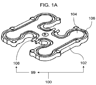
FIG. 1A depicts a perspective view of a mold-tool assembly (100). According to
the
example depicted in FIG. 1A, the mold-tool assembly (100) may include (and is
not limited
to): (i) a manifold assembly (102), and (ii) a thermal-management assembly
(108) that is
positioned relative to the manifold assembly (102). The thermal-management
assembly
(108) is configured to convey, in use, a thermal-management fluid (109).
According to a
variation of the depicted example, the manifold assembly (102) has an outer
surface (104)
defining a groove (106), and the thermal-management assembly (108) is received
in the
groove (106). In addition, the thermal-management assembly (108) may include
(and is not
io further limited to): a tube assembly (113) that is configured to convey,
in use, the thermal-
management fluid (109). According to another variation of the depicted
example, the mold-
tool assembly (100) may include (and is not limited to): the manifold assembly
(102) having
an outer surface (104) defining a groove (106), and the thermal-management
assembly
(108) that is positioned relative to the groove (106): for example, the
thermal-management
assembly (108) may be received in the groove (106). The thermal-management
assembly
(108) may be configured to convey, in use, the thermal-management fluid (109)
(such as
oil, etc). The thermal-management fluid (109) may be defined as: a continuous,
amorphous
substance whose molecules move freely past one another and that has the
tendency to
assume the shape of its container, such as a liquid but not a gas. The thermal-
management
fluid (109) may transfer thermal energy and/or may take away or remove thermal
energy.
The groove (106) may be defined as: a long narrow furrow and/or a channel
and/or
channel.
FIGS. 1B, 10 depict cross sectional side views of the mold-tool assembly
(100). According
to the examples depicted in FIGS. 1B, 10, the thermal-management assembly
(108) may
further include a tube assembly (113) that is configured to convey, in use,
the thermal-
management fluid (109). The tube assembly (113) may be a hollow cylinder that
conveys a
fluid or functions as a passage. The tube assembly (113) may be inflatable or
ridged. The
specific shape of the cylinder is of matter of convenience. The tube assembly
(113) may be
attached to the manifold assembly (102) and/or to the groove (106) by brazing,
potting,
compounding, welding, etc or by being pressed into the groove (106). The
manifold
assembly (102) may include a manifold body 103 that defines a melt channel
(110). A melt
(111) (also known as a resin, etc) is conveyed in the melt channel (110). The
groove (106)
may be defined on a top-facing outer surface (114) of the manifold assembly
(102), or may
be defined on a bottom-facing surface (116) of the manifold assembly (102), or
may be
8
CA 02809854 2013-02-27
WO 2012/040132 PCT/US2011/052238
defined on both (in combination) the top-facing outer surface (114) and the
bottom-facing
surface (116).
FIGS. 2A, 2B depict cross sectional side views of the mold-tool assembly
(100). According
to the examples depicted in FIGS. 2A, 2B, the thermal-management assembly
(108) may
further include (and is not limited to) a plate cover (120) for covering the
groove (106). The
thermal-management fluid (109) touches the groove (106) and the plate cover
(120). It is
understood that the plate cover (120) may be attached to the manifold assembly
(102) by
using many ways (such as): removably attachable mechanisms (such as screws,
bolts),
io permanent bonding, such as welding, brazing, etc.
FIG. 20, 2D are cross sectional side views of the mold-tool assembly (100).
According to
the examples depicted in FIGS. 20, 2D, the plate cover (120) defines a plate
groove (107)
that is configured to convey, in use, the thermal-management fluid (109). The
groove (106)
and plate groove (107) may be defined by manifold assembly (102) and by the
plate cover
(120) respectively.
FIG. 3 depict a cross sectional view of the mold-tool assembly (100).
According to the
example depicted in FIG. 3, the thermal-management assembly 108 may further
include
(and is not limited to) a plurality of thermal-management paths (122) that are
defined by the
manifold assembly (102). Each of the plurality of thermal-management paths
(122) are
configured to convey, in use, the thermal-management fluid (109). The
plurality of thermal-
management paths (122) surround the melt channel (110) that is defined by the
manifold
assembly (102). The are many ways to form the thermal-management paths (122),
such as:
gun drilled holes, 3D metal printing process, etc.
FIGS. 4A, 4B, 40, 4D depict perspective views and cross sectional views of the
mold-tool
assembly (100). According to the examples depicted in FIGS. 4A, 4B, 40, 4D,
the manifold
assembly (102) may include (and is not limited to) a split manifold. That is,
the manifold
assembly (102) may include (and is not limited to): a manifold body (103)
having: a first
manifold body (130), and a second manifold body (132). The thermal-management
assembly (108) includes: complementary-mating thermal-management paths (119)
that are
defined by the first manifold body (130) and the second manifold body (132).
Each of the
complementary-mating thermal-management paths (119) is configured to convey,
in use,
the thermal-management fluid (109). The complementary-mating thermal-
management
9
WO 2012/040132 CA 02809854 2013-02-27
PCT/US2011/052238
paths (119) may be formed on a surface of the first manifold body (130) and
the second
manifold body (132). The manifold assembly (102) may define an inlet (124),
outlets (126)
and the melt channel (110) may connects the inlet (124) with the outlets
(126). Cross
sectional views (FIGS. 4A, 4C, 4D) of the mold-tool assembly (100) are taken
along a cross
sectional line (129). FIG. 4B depicts a top view of the manifold assembly
(102). FIGS. 4C,
4D depict bottom views of the manifold assembly (102). FIG. 4 D depicts a join
line 134
where the first manifold body (130) and the second manifold body (132) are
joined, by
various methods, such as welding, etc.
FIG. 5 depicts a schematic representation of the mold-tool assembly (100).
According to
the example depicted in FIG. 5, the thermal-management assembly (108) may
further
include (and is not limited to) a plate cover (120) defining a plate channel
(121). The
thermal-management fluid (109) is received in the plate channel (121). The
plate cover
(120) may be attached and/or bonded to the surface of the manifold assembly
(102) along
a bonding surface (123).
FIG. 6 depicts a schematic representation of the mold-tool assembly (100).
According to
the example depicted in FIG. 6, the thermal-management assembly (108) may
further
include (and is not limited to): a bladder assembly (125) defining a bladder
channel (117).
The thermal-management fluid (109) may be received in the bladder channel
(117). The
bladder channel (117) may have a bladder inlet (128), and a bladder outlet
(131).
FIG. 7 depicts a schematic representation of the mold-tool assembly (100).
According to
the example depicted in FIG. 7, the thermal-management assembly (108) may
further
include: a plate cover (120) defining a honeycomb channel (133). The thermal-
management fluid (109) may be received, in use, in the honeycomb channel
(133). The the
honeycomb channel (133) may have micro channels, baffles, etc. The honeycomb
channel
(133) may be bonded, etc, to the manifold assembly (102).
FIG. 8 depicts a schematic representation of the mold-tool assembly (100).
According to
the example depicted in FIG. 8, the manifold assembly (102) may further
include (and is not
limited to): a modular component (189), and the thermal-management assembly
(108) may
be coupled with the modular component (189). By way of example, the modular
component
(189) may include (and is not limited to):a modular runner distribution block
(190), a
modular conduit connection body (192), a modular runner drop block (194). The
heat10
CA 02809854 2013-02-27
WO 2012/040132 PCT/US2011/052238
transfer fluid may be used on a single manifold or on a multi-component
manifold system,
such as a cross manifold with main manifolds, or on a low cavity manifold
system
(distributor, tubes and drop blocks, etc).
FIG. 9 depicts a schematic representation of the mold-tool assembly (100).
According to
the example depicted in FIG. 9, the thermal-management assembly (108) may be
received,
at least in part, in the melt channel (110) defined by the manifold assembly
(102). In
addition, the thermal-management assembly (108) may include (and is not
limited to): a
tube assembly (113) that is received, at least in part, in the melt channel
(110) defined by
io the manifold assembly (102). Supports may be used to support and position
the thermal-
management assembly (108) in the melt channel (110).
FIG. 10 depicts a schematic representation of the mold-tool assembly (100).
According to
the example depicted in FIG. 10, the thermal-management assembly (108) may be
attached to a surface of the manifold assembly (102), and thermal-management
assembly
(108) may include the tube assembly (113). The method of attachment of the
tube
assembly (113) to the manifold assembly (102) may be by any suitable
manufacturing
method such as welding or brazing, etc (for example).
FIG. 11 depicts a schematic representation of the mold-tool assembly (100).
According to
the example depicted in FIG. 11, the thermal-management assembly (108) may be
included in a backing plate (142) of the manifold assembly (102). The manifold
assembly
(102) may be in contact with the backing plate (142) via a thermal-transfer
assembly (140).
According to a variation, the thermal-management assembly (108) may be
included in a
puck assembly (144) of a backing plate (142), and the manifold assembly (102)
is in
contact with the backing plate (142) via a thermal-transfer assembly (140).
The thermal-
transfer assembly (140) may include (and is not limited to) an insulator
element (152) for
use with the manifold assembly (102), which may represent a form of heat loss,
and for this
case the insulator element (152) transfers, in use, thermal energy from the
puck assembly
(144) to the manifold assembly (102). The puck assembly (144) may include a
piece or
block of metal (steel, copper, etc) that is embedded in and/or attached to the
backing plate
(142). The puck assembly (144) may be insulated from the backing plate (142).
The puck
assembly (144) may be designed to have heat transfer fluid flow through its
body. The puck
assembly (144) may heat up due to heat transfer fluid and transfer the heat to
the manifold
assembly (102). In this configuration the temperature gradient from a manifold
surface to
11
WO 2012/040132 CA 02809854 2013-
02-27 PCT/US2011/052238
the puck surface of the puck assembly (144) may be tuned (that is, reduced or
increased)
to a value that may be required for the best or optimum function of the mold-
tool assembly
(100). In the case of a thermoset resin molding system (not depicted), it may
be desirable
to keep the mold-tool assembly (100) runner and the mold cavity hot
(relatively hotter), and
therefore, the puck assembly (144) is cooled as may be required for processing
a
thermoset resin. Conversely, in the case for a thermoplastic resin molding
system (not
depicted), the puck assembly (144) may be heated as may be required for
processing
thermoplastic resins.
FIG. 12 depicts a schematic representation of the mold-tool assembly (100).
According to
the example depicted in FIG. 12, the thermal-management assembly (108) may be
included in a heat exchanger (150) that is supported by a backing plate (142).
The manifold
assembly (102) may be in contact with the backing plate (142) via a thermal-
transfer
assembly (140). The thermal-management fluid (109) may be used to heat the
heat
exchanger (150). Heat may be conducted from the heat exchanger (150) to the
manifold
assembly (102) via the heat transfer block. The insulator element (152) may be
used to
keep the backing plate (142) cool or hot depending on the type of resin (melt)
to be
processed, and molding conditions requirements, and to maximize the efficiency
of the heat
exchanger (150). As in the embodiment of FIG. 11 the heat exchanger (150) may
be be
heated for the purpose of processing thermoplastic resins, or may be cooled
for the
purpose of processing thermosetting resins, for example.
ADDITIONAL DESCRIPTION
The following clauses provide further description of the aspects and / or
variations of the
examples: Clause (1): a mold-tool assembly (100), comprising: a manifold
assembly (102);
and a thermal-management assembly (108) being positioned relative to the
manifold
assembly (102), the thermal-management assembly (108) configured to convey, in
use, a
thermal-management fluid (109). Clause (2): the mold-tool assembly (100) of
clause (1),
wherein: the manifold assembly (102) has an outer surface (104) defining a
groove (106);
and the thermal-management assembly (108) is received in the groove (106).
Clause (3):
the mold-tool assembly (100) of any clause mentioned in this paragraph,
wherein: the
thermal-management assembly (108) includes: a tube assembly (113) being
configured to
convey, in use, the thermal-management fluid (109). Clause (4): the mold-tool
assembly
(100) of any clause mentioned in this paragraph, wherein: the thermal-
management
assembly (108) includes: a plate cover (120) covering a groove (106) being
defined by the12
CA 02809854 2013-02-27
WO 2012/040132 PCT/US2011/052238
manifold assembly (102), and the thermal-management fluid (109) touches the
groove
(106) and the plate cover (120). Clause (5): the mold-tool assembly (100) of
any clause
mentioned in this paragraph, wherein: the thermal-management assembly (108)
includes: a
plate cover (120) covering a groove (106) being defined by the manifold
assembly (102),
and the thermal-management fluid (109) touches the groove (106) and the plate
cover
(120), the plate cover (120) defines a plate groove (107) configured to
convey, in use, the
thermal-management fluid (109). Clause (6): the mold-tool assembly (100) of
any clause
mentioned in this paragraph, wherein: the thermal-management assembly 108
includes: a
plurality of thermal-management paths (122) being defined by the manifold
assembly (102),
io each of the plurality of thermal-management paths (122) being configured
to convey, in
use, the thermal-management fluid (109), the plurality of thermal-management
paths (122)
surrounding a melt channel (110) being defined by the manifold assembly (102).
Clause (7):
the mold-tool assembly (100) of any clause mentioned in this paragraph,
wherein: the
manifold assembly (102) includes: a manifold body (103) having: a first
manifold body
(130); and a second manifold body (132), the thermal-management assembly (108)
includes: complementary-mating thermal-management paths (119) being defined by
the
first manifold body (130) and the second manifold body (132), each of the
complementary-
mating thermal-management paths (119) being configured to convey, in use, the
thermal-
management fluid (109). Clause (8): the mold-tool assembly (100) of any clause
mentioned
in this paragraph, wherein: the thermal-management assembly (108) includes: a
plate cover
(120) defining a plate channel (121), and the thermal-management fluid (109)
is received in
the plate channel (121). Clause (9): the mold-tool assembly (100) of any
clause mentioned
in this paragraph, wherein: the thermal-management assembly (108) includes: a
bladder
assembly (125) defining a bladder channel (117), the thermal-management fluid
(109)
being received in the bladder channel (117). Clause (10): the mold-tool
assembly (100) of
any clause mentioned in this paragraph, wherein: the thermal-management
assembly (108)
includes: a plate cover (120) defining a honeycomb channel (133), the thermal-
management fluid (109) received, in use, in the honeycomb channel (133).
Clause (11): the
mold-tool assembly (100) of any clause mentioned in this paragraph, wherein:
the manifold
assembly (102) includes: a modular component (189), and the thermal-management
assembly (108) is coupled with the modular component (189). Clause (12): the
mold-tool
assembly (100) of any clause mentioned in this paragraph, wherein: the thermal-
management assembly (108) is received, at least in part, in a melt channel
(110) defined by
the manifold assembly (102). Clause (13): the mold-tool assembly (100) of any
clause
mentioned in this paragraph, wherein: the thermal-management assembly (108)
includes: a
13
WO 2012/040132 CA 02809854 2013-02-27 PCT/US2011/052238
tube assembly (113) being received, at least in part, in a melt channel (110)
defined by the
manifold assembly (102). Clause (14): the mold-tool assembly (100) of any
clause
mentioned in this paragraph, wherein: the thermal-management assembly (108) is
attached
to a surface of the manifold assembly (102). Clause (15): the mold-tool
assembly (100) of
any clause mentioned in this paragraph, wherein: the thermal-management
assembly (108)
is included in a backing plate (142) of the manifold assembly (102), and the
manifold
assembly (102) is in contact with the backing plate (142) via a thermal-
transfer assembly
(140). Clause (16): the mold-tool assembly (100) of any clause mentioned in
this
paragraph, wherein: the thermal-management assembly (108) is included in a
puck
io assembly (144) of a backing plate (142) of the manifold assembly (102),
and the manifold
assembly (102) is in contact with the backing plate (142) via a thermal-
transfer assembly
(140). Clause (17): the mold-tool assembly (100) of any clause mentioned in
this
paragraph, wherein: the thermal-management assembly (108) is included in a
heat
exchanger (150) being supported by a backing plate (142) of the manifold
assembly (102),
and the manifold assembly (102) is in contact with the backing plate (142) via
a thermal-
transfer assembly (140). Clause (18) a mold-tool assembly (100), comprising: a
manifold
assembly (102); and a constant-temperature heater assembly (99) being
positioned relative
to the manifold assembly (102), the constant-temperature heater assembly (99)
being
configured to convey, in use, a thermal-management fluid (109).
It is understood that the scope of the present invention is limited to the
scope provided by
the independent claim(s), and it is also understood that the scope of the
present invention
is not limited to: (i) the dependent claims, (ii) the detailed description of
the non-limiting
embodiments, (iii) the summary, (iv) the abstract, and/or (v) description
provided outside of
this document (that is, outside of the instant application as filed, as
prosecuted, and/or as
granted). It is understood, for the purposes of this document, the phrase
"includes (and is
not limited to)" is equivalent to the word "comprising". It is noted that the
foregoing has
outlined the non-limiting embodiments (examples). The description is made for
particular
non-limiting embodiments (examples). It is understood that the non-limiting
embodiments
are merely illustrative as examples.
14