Note: Descriptions are shown in the official language in which they were submitted.
CA 02809856 2015-12-01
30219-13
TITLE:
ENERGY RECOVERY VENTILATION SMOKE EVACUATION
RELATED APPLICATIONS
[0001] The present application claims benefit of U.S.
Provisional patent application no. 61/612,997, filed March 20,
2012, entitled "ENERGY RECOVERY VENTILATION SMOKE EVACUATION."
TECHNICAL FIELD
[0002] The present disclosure relates generally to air
handling systems for buildings, and more particularly to energy
recovery ventilation systems, and specifically to methods and
systems for smoke evacuation.
1
CA 02809856 2013-03-20
Attorney Docket No. 142654.00033 (RUS11-105)
PATENT APPLICATION
BACKGROUND OF THE INVENTION
[0003]
Building exhaust fans are used to exhaust air from a
building, such as when there is smoke or carbon dioxide.
However, operation of such building exhaust fans is independent
of other heating, ventilating and air conditioning system
components, which can create conflicts and misoperation with
such components.
2
ak 02809856 2015-12-01
30219-13
SUMMARY OF THE INVENTION
[0004] A control system is provided that includes one or
more smoke sensors, each configured to measure a level of smoke
at a location within a building and to output a smoke level
signal based at least in part upon the measured level of smoke,
such as a smoke detector for a. fire or security system. A
controller receives the smoke level signals and controls the
operation of one or more energy recovery ventilation systems in
a first mode of operation to recover energy when the smoke
level signal is below a predetermined value and in a second
mode of operation to evacuate smoke when the smoke level signal
is above the predetermined value.
[0004a] A method of controlling operation of an energy
recovery ventilation system, comprising: measuring a smoke
level with a smoke sensor; receiving a smoke signal at a
processor from the smoke sensor, wherein said smoke signal is
based at least in part on the smoke level; and controlling an
operation of an energy recovery ventilation system using the
processor, based at least in part on the smoke signal; wherein
the controlling is based at least in part on a predetermined
sequence.
[0005] Other systems, methods, features, and advantages of
the present disclosure will be. or become apparent to one with
skill in the art upon examination of the following drawings and
detailed description. It is intended that all such additional
systems, methods, features, and advantages be included within
this description, be within the scope of the present
disclosure, and be protected by the accompanying claims.
3
CA 02809856 2013-03-20
,
t
,
Attorney Docket No. 142654.00033 (RUS11-105)
PATENT APPLICATION
BRIEF DESCRIPTION OF THE SEVERAL VIEWS OF THE DRAWINGS
[0006]
Aspects of the disclosure can be better understood
with reference to the following drawings. The components in the
drawings are not necessarily to scale, emphasis instead being
placed upon clearly illustrating the principles of the present
disclosure. Moreover, in the drawings, like reference numerals
designate corresponding parts throughout the several views, and
in which:
[0007]
FIGURE 1 is a diagram of an ERV system in accordance
with an exemplary embodiment of the present disclosure;
[0008]
FIGURE 2 is a flow chart of an algorithm for operation
of an ERV control system in accordance with an exemplary
. embodiment of the present disclosure;
[0009]
FIGURE 3 is a flow chart of an algorithm for purge
- 15 operation of an ERV control system, in accordance with an
exemplary embodiment of the present disclosure;
[0010]
FIGURE 4 is a flow chart of an algorithm for pressure
sequence operation of an ERV control system, in accordance with
an exemplary embodiment of the present disclosure;
[0011]
FIGURE 5 is a flow chart of an algorithm for exhaust
sequence operation of an ERV control system, in accordance with
an exemplary embodiment of the present disclosure; and
[0012]
FIGURE 6 is a diagram of a system for controlling an
ERV system in accordance with an exemplary embodiment of the
present disclosure.
4
CA 02809856 2015-12-01
30219-13
DETAILED DESCRIPTION OF THE INVENTION
[0013]
In the description that follows, like parts are marked
throughout the specification and drawings with the same
reference numerals. The drawing figures might not be to scale
and certain components can be shown in generalized or schematic
form and identified by commercial designations in the interest
of clarity and conciseness.
[0014]
The present disclosure is directed to systems and
methods which control energy recovery ventilation (ERV) systems
of buildings. ERV
systems can be used to recover energy and
lower utility expenses.
In one exemplary embodiment, energy
recovery wheels rotate between the incoming outdoor air and the
building exhaust air. As the wheel rotates, it transfers a
percentage of the heat and moisture differential from one
airstream to the other. In this manner, the outdoor air is pre-
conditioned, which reduces the capacity and energy needed from
the mechanical heating, ventilating and =air conditioning (HVAC)
system to process the outdoor air. According to certain
guidelines, building environments require a specific amount of
fresh air to dilute contaminates in the space and provide
ventilation for high concentrations of people. The required
amount of fresh air can be useful to provide dilution of
contaminates and to minimize the possibility of "sick building
syndrome." Furthermore, increasing the amount of outside air
that is introduced into a building intake lowers the carbon
dioxide levels in the building, and can help keep the occupants
alert and healthier. ERVs can also reduce indoor odors with
fresh outside air that is brought into the =building, and allow
stale air to be exhausted out of the building. An exemplary ERV
system is described in U.S. patent 5,548,970.
5
CA 02809856 2015-12-01
30219-13
[0015]
Despite these potential advantages of ERVs, problems
may arise with operating an ERV when smoke is detected in a
building.
Depending on the outcome desired, different schemes
can be used to achieve the desired result, as described herein.
One desired outcome can be to evacuate the smoke from the
building as quickly as possible.
This outcome can be
accomplished by using the air handling unit to move the smoke
out of the building. Another way to accomplish this outcome is
to evacuate the smoke out of the building through the doors or
other building portals, such as by creating positive pressure in
the building. Other suitable schemes can also or alternatively
be implemented.
[0016]
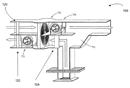
FIGURE 1 is a diagram of an ERV system 100 in
accordance with an exemplary embodiment of the present
disclosure. System 100 can be an air-to-air type heat exchanger
that includes wheel 110, which can also be referred to as an
energy recovery ventilation (ERV) wheel, a thermal wheel or an
enthalpy wheel. As wheel 110 rotates between the incoming fresh
air ventilation stream and outgoing building air exhaust stream,
it can pick up heat energy from the building air and release it
into the colder fresh air stream.
In different seasons, the
inside or the outside air may have more heat and moisture, and
thereby more energy.
[00].7]
System 100 can be used where the outside air is warmer
than the inside air. As can be seen, the conditioned inside air
that is being exhausted can mix with the incoming outside air,
via an opening 112 and wheel 110, to lower the temperature, and
raise the relative humidity. This process helps to reduce the
amount of energy used by the air conditioning and handling
6
CA 02809856 2013-03-20
Attorney Docket No. 142654.00033 (RUS11-105)
PATENT APPLICATION
system to bring the temperature down to the set point of the
system.
[0018]
It will be appreciated that when the outside air is
cooler and the building is to be heated, the exhausted inside
air can be used to warm the incoming outside air to reduce power
consumption of the ERV.
[0019]
System 100 can also include one or more fans or
blowers, including an outside air intake fan 114, and a building
exhaust fan 116 to aid the exchange of air to and from the
building (not shown).
[0020]
System 100 can also include an outside air damper 120
to allow or not allow outside air into the system 100.
Similarly, system 100 can include an exhaust damper 122 to allow
or not allow air out of the exhaust area of the system 100.
System 100 can also include a bypass damper 124. As
shown,
bypass damper is located generally on the side panel of the
exhaust damper.
By maintaining positive pressure in the
building and opening the bypass damper 124, air can be forced
out through the bypass damper 124.
[0021]
FIGURE 2 is a flow chart of an algorithm 200 for
operation of an ERV control system in accordance with an
exemplary embodiment of the present disclosure.
Algorithm 200
can be implemented in hardware or a suitable combination of
hardware and software, and can be one or more software systems
operating on a processor.
[0022]
As used herein, "hardware" can include a combination
of discrete components, an integrated circuit, an application-
specific integrated circuit, a field programmable gate array, or
other suitable hardware. As used herein, "software" can include
one or more objects, agents, threads, lines of code,
subroutines, separate software applications, two or more lines
of code or other suitable software structures operating in two
7
CA 02809856 2013-03-20
Attorney Docket No. 142654.00033 (RUS11-105)
PATENT APPLICATION
or more software applications, on one or more processors (where
a processor includes a microcomputer or other suitable
controller, memory devices, input-output devices, displays, data
input devices such as keyboards or touch screens, peripherals
such as printers and speakers, associated drivers, control
cards, power sources, network devices, docking station devices,
or other suitable devices operating under control of software
systems in conjunction with the processor or other devices), or
other suitable software structures.
In one exemplary
embodiment, software can include one or more lines of code or
other suitable software structures operating in a general
purpose software application, such as an operating system, and
one or more lines of code or other suitable software structures
operating in a specific purpose software application.
As used
herein, the term "couple" and its cognate terms, such as
"couples" and "coupled," can include a physical connection (such
as a copper conductor), a virtual connection (such as through
randomly assigned memory locations of a data memory device), a
logical connection (such as through logical gates of a
semiconducting device), other suitable connections, or a
suitable combination of such connections.
[0023]
Algorithm 200 begins at 202, where it is determined
whether a current smoke level exceeds a predetermined smoke
level. In one exemplary embodiment, the smoke level data can be
obtained from an alarm system or other suitable systems that
utilize smoke detectors, so as to reduce the cost associated
with detecting smoke levels. If it is determined at 202 that the
current smoke level does not exceed the predetermined level, the
algorithm continues to check the smoke level in the building,
and an associated ERV wheel is operated in a first mode of
operation to recover energy and lower utility expenses.
8
CA 02809856 2013-03-20
Attorney Docket No. 142654.00033 (RUS11-105)
PATENT APPLICATION
[0024]
If it is determined at 202 that the smoke level does
exceed a predetermined level, the algorithm proceeds to 204,
where the rotation of the ERV wheel is stopped, such as by
activating a brake, by interrupting current to a drive motor or
in other suitable manners, so as to operate the ERV wheel in a
second mode of operation. The algorithm then proceeds to 206.
[0025]
At 206, it is determined whether to pivot the ERV
wheel out of the airstream, such as based at least in part on
the amount of smoke detected, airflow, and/or other physical
data.
If it is determined at 206 that the wheel should not be
pivoted, the algorithm proceeds to 208 where a bypass damper is
opened, such as by actuating a valve or other suitable actuator,
in order to allow a larger amount of air to be relatively
quickly evacuated from the building through the exhaust damper
_ 15 without pivoting of the ERV.
[0026]
If it is determined at 206 that the ERV wheel should
be pivoted out of the airstream, a suitable control signal is
generated to an electric motor, pneumatic or hydraulic valve or
other suitable devices to cause the ERV wheel to pivot out of
the airstream.
Once the wheel is pivoted out of the airstream
or the bypass damper is opened, the algorithm proceeds to 210
where a sequence is selected. In one exemplary embodiment, the
sequence can be selected based on a predetermined jumper setting
on a control board, through a user interface, or any other
suitable method.
The sequence can also or alternatively be
selected based on information received from sensors in the
system, the type of building, the manner in which the smoke in
the building is to be removed from the building or other
suitable data.
[0027] If a
purge sequence is selected at 210, the algorithm
proceeds to 212 where a purge sequence is initiated. The
exhaust sequence may cause negative pressure to occur in the
9
CA 02809856 2013-03-20
Attorney Docket No. 142654.00033 (RUS11-105)
PATENT APPLICATION
building, such as by closing air intake dampers, turning an
outside air intake fan off and turning a building exhaust fan on
to exhaust smoke from the building without replenishing the
exhausted air, which can be used to create a negative pressure,
such as to prevent fresh air from providing oxygen to the fire.
[0028] A pressurization sequence can be started at 214.
The
pressurization sequence can maintain positive pressure in
critical building areas, such as areas where occupants may
require breathing or, or where it is desired to keep
contaminants out.
Positive pressure can be maintained by
increasing the air intake fan speed and decreasing or stopping
the building exhaust fan speed to keep fresh air going to areas
of the building where people are present.
[0029] An exhaust sequence can be started at 216.
The
. 15 exhaust sequence can be used to create a negative pressure in
the building to both exhaust the smoke and to starve oxygen from
any fire or burning. The air intake dampers can be closed and
the outside air intake fan can be turned off.
The exhaust
dampers can be opened and the building exhaust fan can be turned
on to exhaust smoke from the building.
[0030]
After the smoke detection system indicates that the
smoke has dissipated to an acceptable level, the selected
sequence can continue for a period of time, such as a minute or
two, before normal operation of the system is reinstituted. In
this manner, inadvertent cycling of the system due to traces of
remaining smoke can be avoided.
[0031]
In normal operation, the system can maintain a default
air intake and exhaust volume of air.
The air intake and
building exhaust fans or blowers can increase the airflow if
elevated levels of carbon dioxide or other undesirable gases are
detected, such as by interfacing with a carbon dioxide detector
of a fire detection system or a smoke detection system.
The
CA 02809856 2013-03-20
'
Attorney Docket No. 142654.00033 (RUS11-105)
PATENT APPLICATION
building pressure is maintained as the speed settings of the
fans or blowers are changed to satisfy the carbon dioxide level
requirements.
[0032]
FIGURE 3 is a flow chart of an algorithm 300 for purge
operation of an ERV control system, in accordance with an
exemplary embodiment of the present disclosure.
Algorithm 300
can be implemented in hardware or a suitable combination of
hardware and software, and can be one or more software systems
operating on a processor.
[0033]
Algorithm 300 begins at 302 where the outside air
intake damper and building exhaust damper are opened, such as by
transmitting a suitable control signal to an electronic or
pneumatic damper actuator for each damper, in order to purge the
_
smoke out of the building very rapidly through the ERV system.
The algorithm then proceeds to 304, where air intake fans and
building exhaust fans are actuated, such as by transmitting one
or more suitable control signals to one or more fan controllers.
In one exemplary embodiment, the air intake and building exhaust
fans can be ramped up to a predetermined/preprogrammed speed to
provide fresh intake air to replace the exhausted smoke, the
activation of the air intake and building exhaust fans can be
coordinated to prevent over or under pressures, or other
suitable controls can be used.
The algorithm then proceeds to
306.
[0034]
At 306, it is determined whether the smoke level in
the building exceeds an acceptable level.
In one exemplary
embodiment, smoke levels can be determined using one or more
sensors that are installed at predetermined locations within the
building, the smoke content of building exhaust air can be
determined from a smoke sensor, or other suitable processes can
also or alternatively be used.
If it is determined that the
smoke level does not exceed an acceptable level, the algorithm
11
CA 02809856 2013-03-20
Attorney Docket No. 142654.00033 (RUS11-105)
PATENT APPLICATION
returns to 304 where the fans continue to run, the speed of one
or more fans is increased to purge more smoke from the building,
or other suitable actions are implemented. Otherwise, if it is
determined that the smoke level exceeds an acceptable level, the
algorithm proceeds to 308.
[0035]
At 308, it is determined whether to pivot an ERV wheel
out of the airstream.
In one exemplary embodiment, data from
one or more smoke sensors can be used to determine whether a
level of smoke exceeds a predetermined level, whether a number
of smoke detectors measuring smoke exceeds a predetermined
number of smoke detectors, or whether other predetermined levels
have been exceeded.
If it is determined that the wheel should
not be pivoted out of the airstream at 308, then the algorithm
proceeds to 310 where the bypass damper is closed, such as by
. 15 generating a control signal to actuate an electric or hydraulic
damper actuator or in other suitable manners.
The algorithm
then proceeds to 312, where normal operation is continued.
Likewise, the algorithm proceeds to 312 from 308 if it is
determined that the wheel should be pivoted and after the wheel
has been pivoted, such as by actuating a pivot valve or motor or
in other suitable manners.
[0036]
In operation, algorithm 300 allows a controller or
other suitable device to control one or more damper actuators,
fan controllers or wheel pivot actuators in response to data
from smoke detectors, smoke level monitors, smoke sample devices
or other suitable data regarding the content or presence of
smoke in building air.
Algorithm 300 thus allows smoke to be
quickly evacuated from a building, based on the location and
volume of smoke that is being generated.
[0037]
FIGURE 4 is a flow chart of an algorithm 400 for
pressure sequence operation of an ERV control system, in
accordance with an exemplary embodiment of the present
12
CA 02809856 2013-03-20
Attorney Docket No. 142654.00033 (RUS11-105)
PATENT APPLICATION
disclosure. Algorithm 400 can be implemented in hardware or a
suitable combination of hardware and software, and can be one or
more software systems operating on a processor.
[0038]
Algorithm 400 begins at 402, where outside air intake
and building exhaust dampers are adjusted.
In one exemplary
embodiment, data from one or more pressure sensors can be
received and processed to determine outside air intake and
building exhaust damper configurations and whether a positive
pressure exists within a building.
If it is determined that a
positive pressure does not exist and that the outside air intake
and building exhaust damper configurations are open, then
control signals can be generated to close the outside air intake
and building exhaust dampers, such as by incrementally closing
one or more actuators until a positive pressure is achieved, by
. 15 closing one or more dampers completely, or in other suitable
manners. The algorithm then proceeds to 404.
[0039]
At 404, air intake and building exhaust fans are
operated at predetermined and/or preprogrammed speeds to achieve
the proper pressurization.
In one exemplary embodiment, the
operating speed of one or more air intake and building exhaust
fans can be increased or decreased to maintain a predetermined
positive pressure setting in one or more building areas.
In
this exemplary embodiment, the air intake fan speed can be
increased and the building exhaust fan speed can be decreased in
order to increase a pressure in one or more rooms that are
contained within a zone that is controlled by the air intake and
building exhaust fans, or other suitable processes can also or
alternatively be used. The algorithm then proceeds to 406.
[0040]
At 406, data from one or more smoke detectors, smoke
level monitors, air sampling devices or other suitable devices
is used to determine a smoke level in the building, and it is
determined whether the smoke level exceeds a predetermined
13
CA 02809856 2013-03-20
Attorney Docket No. 142654.00033 (RUS11-105)
PATENT APPLICATION
acceptable level or levels, such as a number of smoke detectors
at which smoke is detected, a level of smoke particulates in one
or more locations or at one or more building exhaust dampers, or
other suitable levels. If it is determined that the smoke level
does not exceed an acceptable level or levels, the algorithm
returns to 404 and the fans continue to run, and/or the speed
can be increased to achieve the proper pressurization in the
critical building areas.
If it is determined that the smoke
level exceeds the acceptable level or levels, the algorithm
proceeds to 408, where it is determined whether to pivot the ERV
wheel out of the airstream.
In one exemplary embodiment, a
decision to pivot the ERV wheel can be based on whether the
dampers and fans are at a maximum possible setting to achieve
smoke reduction, whether smoke levels have reached a
. 15 predetermined level, whether smoke levels are increasing at a
rate that exceeds a predetermined rate, or other suitable data.
If it is determined at 408 not to pivot the ERV wheel out of the
airstream, the algorithm proceeds to 410, where a bypass damper
is closed, such as by generating a bypass damper actuator
control signal.
The algorithm then proceeds to 412, where
normal operation continues.
Likewise, if the ERV wheel is
pivoted at 408, the algorithm proceeds to 412, where normal
operation continues.
[0041]
In operation, algorithm 400 allows a controller or
other suitable device to control one or more damper actuators,
fan controllers or wheel pivot actuators in response to data
from smoke detectors, smoke level monitors, smoke sample
devices, pressure sensors or other suitable data regarding the
content or presence of smoke in building air and air pressure
within one or more rooms or zones of the building.
Algorithm
400 thus allows smoke to be evacuated based on the location and
14
CA 02809856 2013-03-20
Attorney Docket No. 142654.00033 (RUS11-105)
PATENT APPLICATION
volume of smoke that is being generated, while maintaining
predetermined pressurization levels within the building.
[0042]
FIGURE 5 is a flow chart of an algorithm 500 for
exhaust sequence operation of an ERV control system, in
accordance with an exemplary embodiment of the present
disclosure. Algorithm 500 can be implemented in hardware or a
suitable combination of hardware and software, and can be one or
more software systems operating on a processor.
[0043]
Algorithm 500 begins at 502, where the outside air
intake dampers are actuated. In
one exemplary embodiment, one
or more pressure readings can be obtained and one or more
outside air intake dampers can be opened or closed in order to
maintain negative pressure in one or more zones of the building
relative to other building zones, the outside or in other
manners. The algorithm then proceeds to 504.
[0044]
At 504, a speed setting for one or more building
exhaust fans and outside air intake fans are increased or
lowered to achieve a predetermined negative pressure level in
the one or more zones of the building.
In one exemplary
embodiment, the building exhaust fan speed can be increased, the
air intake fan speeds can be lowered or stopped, or other
suitable processes can be used to generate or maintain a
negative pressure in one or more building zones. The algorithm
then proceeds to 506.
[0045] At
506, data from one or more smoke detectors, smoke
level detectors, air monitors or other suitable devices is
processed to determine whether there is an unacceptable level of
smoke in the building.
If the smoke does not exceed an
acceptable level, such a number of rooms in which smoke is
detected, a level of detected smoke particulates or other
suitable levels, the algorithm returns to 504 and the fans
continue to operate, the building exhaust fan speed can be
CA 02809856 2013-03-20
Attorney Docket No. 142654.00033 (RUS11-105)
PATENT APPLICATION
increased, the air intake fan speed can be decreased, or other
suitable fan setting changes are implemented in order to achieve
the proper pressurization in the predetermined building zones.
If it is determined at 506 that the smoke exceeds an acceptable
level, then the algorithm proceeds to 508.
[0046]
At 508, it is determined whether to pivot the ERV
wheel out of the airstream.
In one exemplary embodiment, a
decision to pivot the ERV wheel can be based on whether the
dampers and fans are at a maximum possible setting to achieve
smoke reduction, whether smoke levels have reached a
predetermined level, whether smoke levels are increasing at a
rate that exceeds a predetermined rate, or other suitable data.
If it is determined at 508 not to pivot the ERV wheel out of the
airstream, the algorithm proceeds to 510, where a bypass damper
. 15 is closed, such as by generating a bypass damper actuator
control signal.
The algorithm then proceeds to 512, where
normal operation continues.
Likewise, if the ERV wheel is
pivoted at 508, the algorithm proceeds to 512, where normal
operation continues.
[0047]
In operation, algorithm 500 allows a controller or
other suitable device to control one or more damper actuators,
fan controllers or wheel pivot actuators in response to data
from smoke detectors, smoke level monitors, smoke sample devices
or other suitable data regarding the content or presence of
smoke in building air.
Algorithm 500 thus allows smoke to be
evacuated from a building based on the location and volume of
smoke that is being generated, while maintaining predetermined
pressurization levels within the building.
[0048]
FIGURE 6 is a diagram of a system 600 for controlling
an ERV system in accordance with an exemplary embodiment of the
present disclosure.
System 600 includes smoke sensors 602A
through 602N, controller 604, thermal wheel controllers 606A
16
CA 02809856 2013-03-20
Attorney Docket No. 142654.00033 (RUS11-105)
PATENT APPLICATION
through 606N, damper controllers 608A through 608N, fan
controllers 610A through 610N and pressure sensors 612A through
612N.
[0049]
Smoke sensors 602A through 602N can sense the presence
of smoke in ambient air, can sense the level of smoke in ambient
air and can output a signal generally corresponding to the level
of smoke sensed, can capture a predetermined volume of ambient
air and generate a metric that represents a relative or absolute
number of smoke particulates per unit volume that have been
detected, or can generate other suitable smoke detection data.
In one exemplary embodiment, smoke sensors 602A through 602N can
be associated with an existing smoke detection system, fire
detection system, security system or other suitable systems, so
as to facilitate the implementation and reduce the cost of
. 15 system 600 by utilizing one or more existing ERV wheels, one or
more existing dampers, one or more existing fans or one or more
existing pressure sensors. Smoke sensors 602A through 602N can
be coupled to controller 604 using one or more wireless
communications media, wire line communications media, fiber
optic communications media or other suitable communications
media or combinations of communications media.
[0050]
Pressure sensors 612A through 612N can sense a local
air pressure and can output a signal generally corresponding to
the local air pressure.
Pressure sensors 612A through 612N can
be coupled to controller 604 using one or more wireless
communications media, wire line communications media, fiber
optic communications media or other suitable communications
media or combinations of communications media.
[0051] Thermal wheel controllers 606A through 606N can
generate data that defines a position and speed of one or more
thermal wheels and can receive control data and generate
actuation or power data to control an operation of one or more
17
CA 02809856 2013-03-20
=
Attorney Docket No. 142654.00033 (RUS11-105)
PATENT APPLICATION
electrical motors or actuators, hydraulic or pneumatic actuators
or other suitable devices that can be used to control a speed
and position of one or more thermal or ERV wheels.
Thermal
wheel controllers 606A through 606N can be coupled to controller
604 using one or more wireless communications media, wire line
communications media, fiber optic communications media or other
suitable communications media or combinations of communications
media.
[0052]
Damper controllers 608A through 608N can generate data
that defines a position of one or more dampers and can receive
control data and generate actuation or power data to control an
operation of one or more electrical motors or actuators,
hydraulic or pneumatic actuators or other suitable devices that
can be used to control the position of one or more dampers.
. 15 Damper controllers 608A through 608N can be coupled to
controller 604 using one or more wireless communications media,
wire line communications media, fiber optic communications media
or other suitable communications media or combinations of
communications media.
[0053]
Fan controllers 610A through 610N can generate data
that defines a speed of one or more fans and can receive control
data and generate actuation or power data to control an
operation of one or more electrical motors or other suitable
devices that can be used to control the speed of one or more
fans.
Fan controllers 610A through 610N can be coupled to
controller 604 using one or more wireless communications media,
wire line communications media, fiber optic communications media
or other suitable communications media or combinations of
communications media.
[0054]
Controller 604 can be implemented in hardware or a
suitable combination of hardware and software, and can be one or
more software systems operating on a processor. Controller 604
18
CA 02809856 2013-03-20
Attorney Docket No. 142654.00033 (RUS11-105)
PATENT APPLICATION
is coupled to smoke sensors 602A through 602N, thermal wheel
controllers 606A through 606N, damper controllers 608A through
608N, fan controllers 610A through 610N and pressure sensors
612A through 612N using one or more wireless communications
media, wire line communications media, fiber optic
communications media or other suitable communications media or
combinations of communications media.
In one exemplary
embodiment, controller 604 can receive data from smoke sensors
that indicates the presence or quantity of smoke in the air near
each smoke sensor, a rate of change of smoke content or air
pressure, thermal wheel position data, damper position data, fan
speed data and pressure data and can convert the signals into
information which can be used by controller 604 to control
thermal wheel position controllers, fan speed and damper
position controllers. In
this exemplary embodiment, controller
604 can implement one or more steps of algorithms 300, 400 and
500, or can implement other suitable algorithms or functions.
[0055]
Controller 604 can also control the operation and
position of thermal wheels associated with thermal wheel
controllers 606A through 606N, the position of dampers
associated with damper controllers 608A through 608N, and the
position and operation of fans associated with fan controllers
610A through 610N, based at least in part on the data from smoke
sensors 602A through 602N and pressure sensors 612A through
612N. In
another exemplary embodiment, controller 604 can
receive set point data for fans, dampers and ERV wheels as a
function of smoke level data, pressure data and other suitable
data, where the set point data is used to determine the
operation and control the positions of fans, dampers and ERV
wheels.
Controller 604 can also receive programming that
defines the sequence of operation of the system when smoke is
19
CA 02809856 2015-12-01
30219-13 =
=
detected, such as to maintain a positive or negative pressure,
to expedite evacuation of smoke or for other suitable purposes.
[0056]
Although the present disclosure and its advantages
have been= described in detail, it should be understood that
various changes, substitutions, and alterations can be made
herein without departing from the scope of the disclosure
as defined by the appended claims. Moreover, the
scope of the present application is not intended to be limited
to the particular embodiments of the process, machine,
manufacture, composition of =matter, means, methods, and steps
described =in the specification. As one of ordinary skill in the
art will readily appreciate from the disclosure of the present
disclosure, processes, machines,. manufacture, compositions of
matter, means, methods, or steps, presently existing or later to
be developed that perform substantially the same function or
achieve substantially the same result as the corresponding
embodiments described herein= may be utilized according to the
present disclosure. Accordingly, the appended claims are
intended to include within their scope such processes, machines,
manufacture, compositions= of matter, means, methods, or steps.
The exemplary embodiments disclosed herein may suitably be
practiced in the presence or absence of any element that is not
specifically disclosed herein.
=
=