Note: Descriptions are shown in the official language in which they were submitted.
CA 02809895 2013-02-28
WO 2012/028247 PCT/EP2011/003955
Description
METHOD AND DEVICE FOR SAFELY SWITCHING A PHOTOVOLTAIC
SYSTEM AFTER DIFFERENTIATING THE ARC TYPE
The invention relates to a method for safely switching
a DC voltage system in the event of an arc occurring on
the DC side, in which the direct current generated and
the DC voltage produced are adjusted with respect to
power management. A DC voltage system is understood as
meaning, in particular, a photovoltaic system here.
A DC voltage system of the type mentioned may also be
referred to as a low-voltage system for DC voltages up
to a DC voltage of 1000 V, for example. Such a system
is, for example, a battery system, a system with fuel
cells, an electrical system in a motor vehicle, in
particular in an electric vehicle or a hybrid vehicle,
and a photovoltaic system usually with a number of DC
producers.
A photovoltaic system as a DC system usually comprises
a number of photovoltaic modules (panels) which are
connected in series in so-called strings. A plurality
of strings may also be connected in parallel, thus
forming a photovoltaic generator with a plurality of
photovoltaic modules and one or more strings. In this
case, the number of modules (panels) within a string in
principle determines the DC voltage generated, while
the number of strings connected in parallel determines
the direct current of the photovoltaic generator.
If the photovoltaic system is used to feed electrical
energy converted from solar energy into a public
electricity grid, use is usually made of an inverter
which converts the direct current produced in the
photovoltaic modules into alternating current at an AC
frequency adapted to the grid frequency. In the case of
an off-grid DC voltage or photovoltaic system, the
CA 02809895 2013-02-28
WO 2012/028247 - 2 - PCT/EP2011/003955
energy produced can be buffered or can be directly used
to supply the load.
The inverter or generally a converter ensures, in
conjunction with so-called power management (maximum
power point tracker), that the load always operates at
or at least in the vicinity of the so-called maximum
power point. The power of the photovoltaic system,
which is determined from the product of the DC voltage
and the direct current according to the characteristic
I/U curve of a photovoltaic system, is zero during
idling (Ipc = 0) and in the case of a short circuit (UDC
= 0), that is to say the photovoltaic system does not
output any power in these extreme cases. At the MPP,
the power output by the solar cells and thus by the
photovoltaic modules reaches a maximum. The position of
this maximum power point (operating point) is dependent
on different factors such as, in particular, the solar
radiation, the temperature and ageing phenomena. An
MPPT circuit for (maximum) power management sets the
direct current and the DC voltage of the photovoltaic
generator to the operating point corresponding to the
maximum power.
In such a DC system and thus also in a photovoltaic
system, arcs may occur at different locations and with
different power depending on the system architecture
and as a result of aged or damaged line connections or
cables and as a result of damaged modules. In order to
identify an arc accompanied by a short circuit or
current path interruption, WO 95/25374 discloses the
practice of detecting the electromagnetic radiation
coming from the arc and of safely switching the circuit
section having the short circuit or the current path
interruption in order to protect the system.
The invention is based on the object of specifying a
particularly suitable method for safely switching such
CA 02809895 2013-02-28
WO 2012/028247 - 3 - PCT/EP2011/003955
a DC system, in particular a photovoltaic system, in
the event of an arc occurring. The intention is also to
specify a device suitable for carrying out the method.
With regard to the method, the object is achieved,
according to the invention, by the features of claim 1.
The subclaims which refer back to the latter relate to
advantageous developments.
In this respect, in the event of an arc detected using
sensors, the power management of the system or load is
adjusted and a power change in the arc is detected. In
the event of a power drop in the arc caused by the
power adjustment, a serial or parallel arc is
identified on the basis of the adjustment direction of
the power management. In this case, a direct current
interruption is initiated in the case of a serial arc
and a short-circuit current is produced, that is to say
a short circuit is deliberately forced, in the case of
a parallel arc.
In an expedient refinement, the power management is
adjusted in the idling direction, that is to say in the
direction of increasing DC voltage, by an adjustment
amount and a power change in the arc is detected. This
adjustment direction is preferred if at least rough
qualification of the type of arc as a serial arc is
already possible on the basis of sufficiently
meaningful sensor data. Otherwise, if the sensor data
classify the arc as a parallel arc with overwhelming
probability, the power management or the
current/voltage or power/voltage operating point is
adjusted in the short-circuiting direction. If a power
drop, for example quenching of the arc, is determined
as a result of the adjustment of the power management,
a serial or a parallel arc is identified depending on
the previous power management adjustment direction.
Otherwise, that is to say in the event of no power
CA 02809895 2013-02-28
WO 2012/028247 - 4 - PCT/EP2011/003955
change or a power increase in the arc, the power
management is first of all reset by the adjustment
amount and is then shifted by an adjustment amount in
the respective opposite adjustment direction.
In this case, the invention is based on the knowledge
that a DC voltage or photovoltaic system is safely
switched in a reliable manner when quenching of the arc
is also ensured by the protective measure taken. As is
known, in the case of a serial arc, the load or
inverter must therefore be isolated from the DC voltage
generator and must therefore be switched off in order
to interrupt or extinguish the arc. This is because if
the load or inverter is disconnected from the DC
generator as a result of such an isolating circuit in
the case of a parallel arc, only the arc remains as the
load, with the result that the entire remaining direct
current flows via the arc and accordingly strengthens
the latter, rather than extinguishing it.
Therefore, the inverter or the load should be short-
circuited on the DC side in the case of a parallel arc.
Since, as is known, the majority of possible arcs can
now be classified as serial arcs, on the one hand, and
parallel arcs, on the other hand, a detected arc should
first of all be identified as a serial or parallel arc,
which would only be possible with extreme difficulty
using sensors or else only with a considerable outlay
on sensors.
On the basis of this knowledge, the invention is now
based on the consideration that the power behavior of
an arc occurring in such a system can first of all be
detected in a simple manner using sensors independently
of the arc type (serial or parallel), while it is then
possible to identify the arc type independently of the
sensor by means of a controlled intervention in the
power management. This is because if the operating
CA 02809895 2013-02-28
WO 2012/028247 - 5 - PCT/EP2011/003955
point, that is to say the power management, is adjusted
(detuned) in the idling direction and the arc power
drops as a result, a serial arc can be reliably
inferred. In a similar manner, when the power
management or the operating point is adjusted in a
targeted manner and there is a power drop in the arc
which is caused thereby and is detected using sensors,
a parallel arc can be reliably inferred.
The identification as a serial or parallel arc then
forms the control criterion for an isolating switch,
for example, in the current path on the DC side or for
controlling a short-circuiting switch for the load or
for the inverter or converter on the DC side into its
closed position. With appropriately designed inverters
or converters, these short-circuiting switch and
isolating switch functions can also be integrated in
the inverter or converter function by means of
corresponding electronic circuit measures.
With regard to the device, the object is achieved,
according to the invention, by the features of claim 6.
The subclaims which refer back to the latter relate to
advantageous refinements.
In this respect, the device comprises a controller for
power management or for adjusting or setting the
operating point of the system. At least one arc sensor
which is connected to the controller is connected
upstream of a converter on the DC side. Depending on
the type of DC system, the converter may be an inverter
(DC/AC converter), a DC/DC converter, a charge
regulator or the like.
The controller is used to adjust the power management
if an arc has been detected using sensors. The
controller classifies the arc as a serial or parallel
arc using the detected power change in the arc and on
CA 02809895 2013-02-28
WO 2012/028247 PCT/EP2011/003955
- 6 -
the basis of the adjustment direction of the power
management. If the arc is classified as a serial arc,
the controller isolates the converter on the DC side
and, if the arc is classified as a parallel arc, the
controller short-circuits the converter on the DC side.
In order to safely switch the system, an isolating
switch connected in series upstream of the converter
and a short-circuiting switch connected in parallel
with the converter are suitably provided, which
switches are connected to a control output of the
controller. In the case of a serial arc, the controller
controls the isolating switch into its open position,
while, in the case of a parallel arc, the controller
controls the short-circuiting switch into its closed
position. The power management or the operating point
can be adjusted, in particular in the case of an
inverter, by changing the impedance.
An exemplary embodiment of the invention is explained
in more detail below using a drawing, in which:
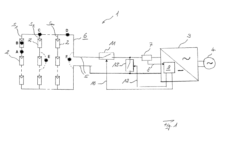
fig. 1 schematically shows a photovoltaic system
having a number of photovoltaic modules
connected in strings and having a sensor on the
DC side and having an inverter with a
controller on the DC side for power management,
and
fig. 2 shows an I/U and P/U characteristic curve of
the controller for power management, which
characteristic curve can be adjusted on an arc-
specific basis.
Fig. 1 schematically shows a photovoltaic system 1
having a number of photovoltaic modules 2 which can be
provided with bypass diodes and are connected to form a
plurality of strings S. The strings Sn are connected to
a common inverter 3 which converts the direct current
CA 02809895 2013-02-28
WO 2012/028247 - 7 - PCT/EP2011/003955
produced by the photovoltaic modules 2 into alternating
current and feeds the latter into a (public)
electricity grid 4. On the DC side, an arc sensor 7 is
connected, via a supply line 5, between the
photovoltaic modules 2, which form the photovoltaic
generator 6 and are connected in series or parallel,
and the inverter 3. The arc sensor 7 is connected, on
the output side, via a signal line 8, to a controller 9
for power management (MPPT) which is assigned to the
inverter 3 in the exemplary embodiment. The controller
9 is connected, on the output side, via a first control
line 10, to an isolating switch 11 which is connected
in series into the supply line 5. The controller 9 is
connected, via a second control line 12, to a short-
circuiting switch 13 which is connected into the supply
line 5 in parallel with the inverter 3 on the DC side.
If an arc occurs inside the photovoltaic system 1, the
arc is detected by the sensor 7 and a corresponding
sensor signal is transmitted to the controller 9 via
the sensor line 8. The sensor 7 may be a sensor for
detecting, in particular, steep-edged current changes,
as is known from WO 2005/098458 Al. Such detected fast
current changes can be evaluated inside the sensor 7 or
else using the controller 9 according to the method
known from DE 10 2007 013 712 Al.
In order to detect an arc, it is possible to also use
evaluation of the (analog) sensor signal on the basis
of a particular pulse density of instances in which a
1-bit comparator exceeds a threshold value as a result
of an arc, in which case a particular pulse density -
that is to say a particular number of pulses per unit
time - is defined, from which an arc detected using
signaling can be assumed. The concept which is already
inventive per se involves subjecting an (analog) sensor
signal to density evaluation of the digital pulses
which can be generated as a result of arcs and
CA 02809895 2013-02-28
WO 2012/028247 - 8 - PCT/EP2011/003955
producing these in a manner which is favorable in terms
of computation time and storage space using a 1-bit
comparator instead of complicated pattern recognition
means and multidigit bit arithmetics.
The controller 9 classifies the arc and, depending on
the arc type, generates a control signal for isolating
the supply line 5. For this purpose, the controller 9
provides, via the control line 10, a corresponding
signal for opening the isolating switch 11.
Alternatively, the controller 9 generates a control
signal that is supplied to the short-circuiting switch
13 via the control line 12 and controls said switch
into Lhe closed position 13. Consequently, the inverter
3 is either isolated from the photovoltaic generator by
opening the isolating switch 11 or else is short-
circuited by closing the short-circuiting switch 13.
The type of safe switching depends on whether the arc
has been classified as a serial arc or as a parallel
arc.
The arcs indicated in fig. 1 and designated with the
capital letters A to D are serial arcs, while the arcs
designated with E and F are parallel arcs. A serial arc
occurs, for example, inside a string S. (A), in a
photovoltaic module 2 (B), at a string connection (C)
or on a collecting line (D) to the inverter 3. A
parallel arc may occur with respect to one or more
modules 2 (E) or the inverter 3 (F). However, an arc
(not illustrated here) may furthermore occur between
two strings S. with a considerably lower degree of
probability.
Arc sensors coupled serially in the strings S. or in the
collecting line outside or inside the inverter 3 can
also generally not distinguish between serial and
parallel arcs using complicated high-frequency sensors.
Even with the inclusion of highly sensitive low-
CA 02809895 2013-02-28
WO 2012/028247 - 9 - PCT/EP2011/003955
frequency current sensors, it is not possible to
reliably classify the arc on account of source current
and source voltage fluctuations caused by cloud cover
since considerable reverse currents from the
conventionally provided capacitor of the inverter 3 can
be observed in the arc case F, for example during arc
ignition. In the arc case E, only small current drops
can additionally be ascertained in strings Sn with a
large number of modules 2 connected in series.
Alternative concepts require a large number of voltage
sensors, to be precise, in principle, on each module 2
and on the inverter 3, which sensors must be evaluated
in a complicated manner in a central unit.
If, in contrast, a serial arc (A to D) is identified,
said arc is extinguished by opening the isolating
switch 11 or a string isolator which is possibly
provided. In contrast, when a parallel arc (E, F) is
identified, the arc at the input of the inverter 3 can
be extinguished by means of a controlled short circuit
which is caused by closing the short-circuiting switch
13.
In order to classify an arc detected using the sensor
7, the controller 9 is used to influence the power
management of the inverter 3 or of the photovoltaic
generator 6 in a targeted manner. In this respect, fig.
2 shows, in the (upper) I/U characteristic curve I(U),
the typical current/voltage profile of the photovoltaic
generator 6. The (lower) P/U characteristic curve P(U)
shows the power profile of the photovoltaic generator
6, which results according to the relationship P=I x U,
on the basis of the DC voltage U produced.
It is possible to see that the power P output by the
photovoltaic generator 6 is respectively zero (P = 0)
both during idling Uo, in which the generator voltage U
is at a maximum and the generator current I is equal to
CA 02809895 2013-02-28
WO 2012/028247 - 10 - PCT/EP2011/003955
zero, and in the short-circuit case Ik in which the
generator voltage U is equal to zero and the short-
circuit current Ik flows. The power Pmax output by the
photovoltaic generator 6 reaches a maximum at a
particular point which is denoted MPP (maximum power
point). The controller 9 for power management, which is
also referred to as maximum power point tracking
(MPPT), adjusts the power management and thus the
operating point as exactly as possible by means of
appropriate control or regulation, with the result that
a connected load, the inverter 3 in the present case,
always operates at this operating point MPP and thus at
maximum power Pmix.
The arc detected using sensors is classified as a
serial or parallel arc by means of the controller 9 by
adjusting or detuning the power management and thus the
operating point MPP or Pmax by a particular adjustment
amount APoo, API), in the idling direction U0 or in the
short-circuiting direction Ik. This adjustment may be
effected, for example, by changing the impedance of the
inverter 3 in the direction of increased or reduced
impedance.
Whether the power management MPP is first of all
adjusted in the idling direction Uo or in the short-
circuiting direction Ix, this can be effected, with a
sufficiently sensitive sensor system, according to a
degree of probability for a serial or parallel arc
which can already be determined using the data from the
sensor 7. In this case, the power management is
adjusted in the idling direction U0 in a targeted
manner, for example in the case of a serial arc which
is predetermined with a relatively high degree of
probability. As a result, a power drop in the arc is
expected. If such a power drop in the arc occurs, a
serial arc is reliably identified. Otherwise, if no
power change or even a power increase in the arc is
CA 02809895 2013-02-28
WO 2012/028247 - 11 - PCT/EP2011/003955
sensed, the power management is reset by the adjustment
amount LPN. The power management MPP is then adjusted
by the adjustment amount API), in the short-circuiting
direction 'lc. If a power drop in the arc is then
detected, a parallel arc is reliably identified and the
corresponding safe switching of the system 1 is
initiated by virtue of the controller 9 causing the
short-circuiting switch 13 to be closed.
If, in contrast, a parallel arc can be classified with
a relatively high degree of probability from the sensor
signal from the sensor 7, the controller first of all
causes the power management MPP to be adjusted by the
adjustment amount LPIk in the short-circuiting direction
Ik. In this case, the power management is adjusted in
the short-circuiting direction Ik in a targeted manner,
for example in the case of a parallel arc which is
predetermined with a relatively high degree of
probability. As a result, a power drop in the arc is
again expected. If such a power drop in the arc occurs,
a parallel arc is reliably identified. Otherwise, if no
power change or even a power increase in the arc is
sensed, the power management is reset by the adjustment
amount L,Pik. The power management MPP is then adjusted
by the adjustment amount APoo in the idling direction
Uo. If a power drop in the arc is then detected, a
serial arc is reliably identified and the corresponding
safe switching of the system 1 is initiated by virtue
of the controller 9 causing the isolating switch 11 to
be opened.
A corresponding increase or reduction in the impedance
of the inverter 3 starting from the current operating
point of the inverter 3 in each case is also similar to
such adjustment of the power management in the idling
or short-circuiting direction.
CA 02809895 2013-02-28
WO 2012/028247 - 12 - PCT/EP2011/003955
If a sequence of arcs which burn for a comparatively
short time occur instead of arcs which burn for a
comparatively long time, for example on account of
vibrations, the power analysis or quenching check can
be expanded to the sequences of arcs. In this respect,
a check is carried out in order to determine whether
only low-power arcs occur with the corresponding power
adjustments or impedance changes or whether re-ignition
of arcs is prevented.
If a plurality of arc sensors are used only in the
strings Si-, or else in the strings Sn and in the
collecting line in a relatively large system 1 and an
arc which occurs can also be reliably assigned to a
string Sn, a string isolator which is possibly present
can also be opened instead of the isolating switch 11
when a serial arc is identified. If, however, it is not
possible to clearly determine a string or if the arc is
detected in the main line or supply line 5, the method
according to the invention is carried out, that is to
say the power management is adjusted in the idling
direction U0 and/or in the short-circuiting direction
Ik.
The system 1 may generally be a DC voltage system
having a DC generator for relatively high DC voltages
(approximately 1000 V), which DC generator consists of
a number of individual DC producers for example. A
converter (DC-DC converter, AC-DC converter, charge
regulator or the like) with impedance
regulation/control and power management then generally
forms the inverter 3.
CA 02809895 2013-02-28
WO 2012/028247 - 13 - PCT/EP2011/003955
List of reference symbols
1 DC/photovoltaic system
2 Module
3 Inverter/converter
4 Public grid
Supply line
6 DC/photovoltaic generator
7 Arc sensor
8 Signal line
9 Controller
Control line
11 Isolating switch
12 Control line
13 Short-circuiting switch
A-D Serial arc
E, F Parallel arc
Sn String